VYDQV50LVENTILATION FAN
HANWAY TECHNOLOGY CO., LTD.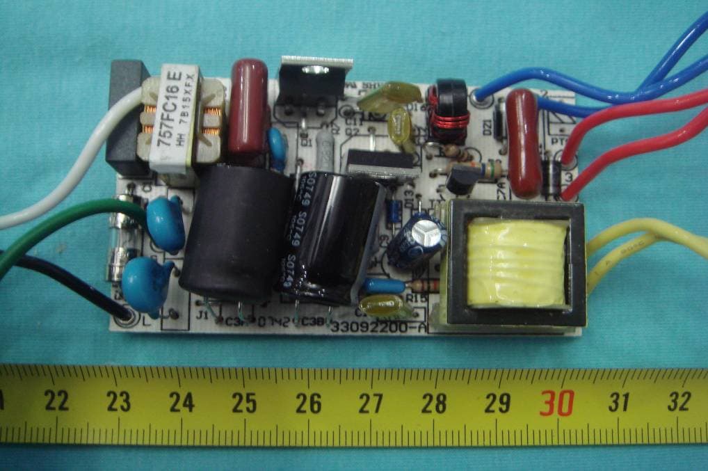
Click to zoom
Application Details
- Equipment Class
- 8CC - Part 18 Consumer Device
- Date of Grant
- Mar 02, 2008
- Application Purpose
- Original Equipment
- Date of Application
- Mar 02, 2008
- Equipment Note
- VENTILATION FAN
- Frequency Range
- 0.04500000 - 0.04500000
- Company
- HANWAY TECHNOLOGY CO., LTD.
- Country
- China
Documents & Files
Document Text
Text extracted from the exhibit documents filed with the FCC. Open a document above to read the original.
Users Manual
Quiet Ventilation Fan/ Light/Nightlight READ AND SAVE THESE INSTRUCTIONS GENERAL SAFETY INFORMATION........................................................................ ...2........................... DESCRIPTION...................................................................................................................................3 COMPONENT PARTS.........................................................................................................................3 DIMENSIONS....................................................................................................................................4 SPECIFICATIONS..............................................................................................................................4 INSTALLATION..................................................................................................................................5 CLEANING & MAINTENANCE..............................................................................................................7 TROUBLE SHOOTING GUIDE.............................................................................................................7 SERVICE PARTS................................................................................................................................8 WARRANTY......................................................................................................................................9 Models QV50L/QV80L/QV110L/QV150L INSTALLATION INSTRUCTIONS The Honeywell trademark is used under license from Honeywell Intellectual Properties Inc. by Lonon Industry Company, Ltd. Honeywell International Inc. makes no representations or warranties with respect to this product. TABLE OF CONTENTS Quiet Decorative Ventilation Fan/Light/Nightlight Models QDV70L/QDV80L/QDV90L/ QDV110L/QDV130L/QDV150L Page 2 Fig.A WARNING: TO REDUCE THE RISK OF FIRE, ELECTRIC SHOCK, OR INJURY TO PERSONS, OBSERVE THE FOLLOWING: 1. Use this unit only in the manner intended by. If you have questions, please contact at the address or telephone number listed in the warranty. 2. Before servicing or cleaning unit, switch the power off at service panel and lock the service disconnecting means to prevent power from being switched on accidentally. When the service disconnecting means cannot be locked, securely fasten a prominent warning device, such as a tag, to the service panel. 3. Installation work and electrical wiring must be done by a qualified person(s) in accordance with all applicable codes and standards, including fire-rated construction codes and standards. Lonon USA, LLC Lonon USA, LLC 4. Sufficient air is needed for proper combustion and exhausting of gases through the flue (chimney) of fuel burning equipment to prevent back drafting. Follow the heating equipment manufacturer's guideline and safety standards, such as those published by the National Fire Protection Association (NFPA) and the American Society for Heating, Refrigeration and Air Conditioning Engineers (ASHRAE), and the local code authorities. 5. When cutting or drilling into wall or ceiling, make sure not to damage electrical wiring and other hidden utilities. 6. Ducted fans must always be vented to the outdoors. 7. NEVER place a switch where it can be reached from a tub or shower. 8. Please note that solid state controls may cause harmonic distortion that can cause motor humming noise. 9. To reduce the risk of fire or electric shock, do not use this fan with any solid-state speed control device. 10. Not to be in a ceiling thermally insulated to a value greater than R40. 11. Fluorescent models only: Do not use a dimmer switch to control the light of this unit. 12. Motor and grille assembly must be installed with housing assembly that are marked (on their cartons) to indicate the suitability with this model. Other housing assembly cannot be substituted. 13. To reduce the risk of fire use only these 18 watt fluorescent lamps and 4 watt maximum type C incandescent lamp nightlight. 1. Do not install this ventilating fan where air temperature may exceed 104 F (40 C). 2. Make sure that the electric service supply voltage is 120V, 60Hz. 3. Follow all local electrical and safety codes, as well as the National Electrical Code (NEC) and the Occupation Safety and Health Act (OSHA). 4. Always disconnect the power source before working on or near the fan, motor or junction box or light fixture. 5. Protect the power cord from sharp edges, oil, grease, hot surfaces, chemicals or other objects. 6. Do not kink the power cord. 7. This unit is approved for use over a bathtub or shower when installed in a GFCI protected branch circuit. 8. This unit must be grounded. 9. This unit is U.L. Listed. Type I.C. Inherently protected. 10. These models are UL listed for tub and shower enclosures. 11. Provide suction parts with proper ventilation. 12. Do not install the unit where ducts are configured as shown in Fig.A. GENERAL SAFETY INFORMATION 1. For general ventilating use only. 2. This product is designed for ceiling installation only. This product is designed for installation in ceilings up to a 12/12 pitch. Ductwork must point up. DO NOT MOUNT THIS PRODUCT ON A WALL. 3. The light fixture assembly must be mounted to the fan housing assembly included with this product. Do not mount the fight fixture assembly to a wiring outlet box. 4. To avoid motor bearing damage and noisy and / or unbalanced impellers, keep drywall spray, construction dust, etc. off power unit. 5. Please read specification label on product for further information and requirements. 6. Not for use in cooking area (Fig. B). Do not use to exhaust hazardous or explosive materials and vapors. CAUTION: Fig.B (Cooking area) Do not install above or inside this area Cooking equipment Floor 45 45 Page 3 DESCRIPTION Thank you for selecting this high quantity Honeywell ventilation fan. Honeywell ventilation fans were designed with your comfort in mind. With many different…
Text truncated - open the document above for the full version.
Block Diagram
Block Diagram Power Supply (AC120V/60Hz) Electrical Ballast Terminal AC/DC Transfer Circuit Transfer Circuit(45KHz) BoosterCircuit Two 18 watt Compact Fluorescent Lamps Protection Circuit for lamp abnormity Electronic Ballast Power Supply (AC120V/60Hz) Blower Wheel Terminal Motor Power Supply (AC120V/60Hz) Night Light Terminal Night Light
Cover Letter(s)
中 山 市 汉 伟 科 技 有 限 公 司 Hanway Technology Co., Ltd. 广东省中山市南头镇同济路贝莱尔工业园 Tel: 0760-3122908 Fax: 0760-3122919 FCC ID: VYDQV50L FCC ID: VYDV50L POWER OF ATTORNEY Feb.29, 2008 Federal Communications Commission Authorization and Evaluation Division 7435 Oakland Mills Road Columbia, MD 21046 To Whom It May Concern: We, the undersigned, hereby authorize Waltek Services (Hongkong) Co., Ltd. (Philo Zhong) on our behalf, to apply to the Federal Communications Commission on our equipment. Any and all acts carried out by Waltek Services (Hongkong) Co., Ltd. (Philo Zhong) on our behalf shall have the same effect as acts of our own. This authorization expires on Mar.1, 2009. This is to advise that we are in full compliance with the Anti-Drug Abuse Act. We, Hanway Technology Co., Ltd., are not subject to a denial of federal benefits pursuant to Section 5301 of the Anti-Drug Act of 1988, 21 USC853a, and no party to the application is subject to a denial of federal benefits pursuant to that section. Sincerely, Hanway Technology Co., Ltd. ------------------------------- John Liu Project Engineer
ID Label/Location Info
FCC ID Label Sample for Model QV50L(BF50QL), QV80L(BF80QL), QV90L(BF90QL), QV110L(BF110QL), QV130L(BF130QL), QV150L(BF150QL), QDV70L(BF70QDL), QDV80L(BF80QDL), QDV90L(BF90QDL), QDV110L(BF110QDL), QDV130L(BF130QDL), QDV150L(BF150QDL) FCC ID: VYDQV50L
ID Label/Location Info
FCC ID Label This device complies with Part 18 of the FCC Rules. Operation is subject to the following two conditions:(1)this device may not cause harmful interference, and (2) this device must accept any interference received, including interference that may cause undesired operation. The Label must not be a stick-on paper. The Label on these products must be permanently affixed to the product and readily visible at the time of purchase and must last the expected lifetime of the equipment not be readily detachable. Proposed Label Location on EUT EUT Top View/ proposed FCC Mark Location FCC ID: VYDQV50L This device complies with Part 18 of the FCC Rules.
Internal Photos
PCB-Front View PCB-Back View
Operational Description
When the power supply is connected to the electronic ballast terminal , the power is transmitted through electrical ballast terminal to the ballast. The ballast will change the power that the compact fluorescent lamp need and provide it for the compact fluorescent lamp. Two 18 watt compact fluorescent lamps will consume the power that has been changed by ballast and make light. When the power supply is connected to the blower wheel terminal , the power is transmitted through blower wheel terminal to the motor. The motor will change the power to the mechanical energy, and make the impeller rotated. When the power supply is connected to the night light terminal , the power is transmitted through night light terminal to the nigh light. The night light will consume the power and make light. Circuit Description
Test Report
FCC TEST REPORT Page 1 of 20 FCC ID : VYDQV50L Applicant : Hanway Technology Co., Ltd. BNN Industrial Zone, Tongji Rd., Nantou Town, Zhongshan, Guangdong, P.R.China Equipment Under Test (EUT) : Product description : Ventilation Fan Model No. : QV50L(BF50QL), QV80L(BF80QL), QV90L(BF90QL), QV110L(BF110QL), QV130L(BF130QL), QV150L(BF150QL), QDV70L(BF70QDL), QDV80L(BF80QDL), QDV90L(BF90QDL), QDV110L(BF110QDL), QDV130L(BF130QDL), QDV150L(BF150QDL) Standards : FCC Part 18 Date of Test : Feb.29, 2008 Test Engineer : Tiger Su Reviewed By : PERPARED BY: Waltek Services (Shenzhen) Co., Ltd. 8C,West Tower, Aidi Building, No.5003 Binhe Rd, Futian District, Shenzhen518045, Guangdong, China. Tel: 86-755-83551033 Fax: 86-755-83552400 Hanway Technology Co., Ltd. FCC ID: VYDQV50L Page 2 of 20 2 Contents Page 1 COVER PAGE..........................................................................................................................................................1 2 CONTENTS ..............................................................................................................................................................2 3 TEST SUMMARY....................................................................................................................................................3 4 GENERAL INFORMATION..................................................................................................................................4 4.1 CLIENT INFORMATION............................................................................................................................................4 4.2 GENERAL DESCRIPTION OF E.U.T...........................................................................................................................4 4.3 DETAILS OF E.U.T. .................................................................................................................................................4 4.4 DESCRIPTION OF SUPPORT UNITS...........................................................................................................................4 4.5 STANDARDS APPLICABLE FOR TESTING..................................................................................................................4 4.6 TEST METHODOLOGY.............................................................................................................................................4 4.7 TEST FACILITY........................................................................................................................................................5 4.8 TEST LOCATION......................................................................................................................................................5 5 EQUIPMENT USED DURING TEST ...................................................................................................................6 6 CONDUCTED EMISSION TEST ..........................................................................................................................7 6.1 TEST EQUIPMENT....................................................................................................................................................7 6.2 TEST PROCEDURE...................................................................................................................................................7 6.3 CONDUCTED TEST SETUP.......................................................................................................................................8 6.4 EUT OPERATING CONDITION.................................................................................................................................8 6.5 CONDUCTED EMISSION LIMITS...............................................................................................................................9 6.6 SPECTRUM ANALYZER............................................................................................................................................9 6.7 FREQUENCY RANGE OF MEASUREMENTS.............................................................................................................10 6.8 CONDUCTED EMISSION TEST RESULT...................................................................................................................10 6.8.1 Measurement Data .....................................................................................................................................10 7 PHOTOGRAPHS OF TESTING..........................................................................................................................13 7.1 CONDUCTED EMISSION TEST VIEW.......................................................................................................................13 8 PHOTOGRAPHS-CONSTRUCTIONAL DETAILS .........................................................................................14 8.1 EUT WITH GLASS CHIMNEY-FRONT VIEW............................................................................................................14 8.2 EUT WITH GLASS CHIMNEY-BACK VIEW..............................................................................................................14 8.3 EUT WITH GLASS CHIMNEY -OPEN VIEW..............................................................................................................15 8.4 EUT WITH PLASTIC CHIMNEY-FRONT VIEW..........................................................................................................16 8.5 EUT WITH PLASTIC CHIMNEY-BACK VIEW...........................................................................................................16 8.6 EUT WITH PLASTIC CHIMNEY -OPEN VIEW...........................................................................................................17 8.7 ELECTRONIC BALLAST-FRONT VIEW....................................................................................................................18 8.8 ELECTRONIC BALLAST-BACK VIEW..…
Text truncated - open the document above for the full version.
Test Setup Photos
Conducted Emission Test View
Contact Information
Applicant
JOHN LIU(PROJECT MANAGER)
Test Firm
Solid Industrial Co., Ltd.Yang Dengfang
Technical Specifications
| # | Rule Parts | Frequency Range | Power Output |
|---|---|---|---|
| 1 | 18 | 0.045 MHz - 0.045 MHz | - |
Other Applications from HANWAY TECHNOLOGY CO., LTD.
VYDV50L
Mar 06, 2008VENTILATION FAN
Equipment Class
8CC - Part 18 Consumer Device