VYDV50LVENTILATION FAN
HANWAY TECHNOLOGY CO., LTD.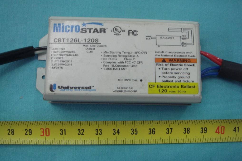
Click to zoom
Application Details
- Equipment Class
- 8CC - Part 18 Consumer Device
- Date of Grant
- Mar 06, 2008
- Application Purpose
- Original Equipment
- Date of Application
- Mar 06, 2008
- Equipment Note
- VENTILATION FAN
- Frequency Range
- 0.04500000 - 0.04500000
- Company
- HANWAY TECHNOLOGY CO., LTD.
- Country
- China
Documents & Files
Document Text
Text extracted from the exhibit documents filed with the FCC. Open a document above to read the original.
Users Manual
Installation instructions Before operating this unit, please read and save these instructions carefully. The HoneywellTrademark isused underlicense fromHoneywell IntellectualProperties Inc.by Lonon Industry Company, Ltd. Honeywell International Inc. Makesno representations orwarranties withrespect tothis product. Page1 Honeywell Decorative Ventilation Fan/Light/Nightlight CLEANING &MAINTENANCE...........................................................................10 SERVICE PARTS..............................................................................................11 ACCESSORIES................................................................................................2 DESCRIPTION................... . ............................................................................3 DIMENSION............................................... .....................................................3 SPECIFICATIONS.............................................................................................4 GENERAL SAFETYINFORMATION....................................................................4 INSTALLATION................................................................................................6 WARRANTY....................................................................................................13 Table of Contents Ventilation Fan/Light/Nightlight Model V50L/V70L/V80L/V90L /V100L/V110L Model ModelDV50L/DV70L/DV80L /DV90L/DV100L/DV110L Part namePicturePart namePicture Quantity Quantity Grille pan 1 1 Screw A M4X10 Light unit 26W Fluorescent Lamp 2 4 1 4 4 Screw B M4X12 Screw C M4X30 4 4 1 Glass panel unit Decorative cap Nut Bolt ACCESSORIES(DV50L/DV70L/DV80L/DV90L/DV100L/DV110L) 4W Incandescent Lamp 1 Part namePicture Part namePicture Quantity Quantity Grille Screw B M4X30 1 1 Screw A M4X10 Light unit 26W Fluorescent Lamp 2 4 1 A ACCESSORIES(V50L/V70L/V80L/90L/V100L/V110L) 4W Incandescent Lamp 1 Page2 DIMENSION(DV50L/DV70L/DV80L/DV90L/DV100L/DV110L) B 2 7/8 AxA 4 H D F E C Honeywell Ventilation Fanswere designedwith yourcomfort inmind. Withmany different features, Honeywellfans fityour needswhether yourbathroom isbig orsmall, needsa light, no lightor evena nightlight,Honeywell fanshave thefeatures youneed. Honeywell Ventilation Fansare someof thequietest fansever tested.Steamy mirrors, damp wallsand foggywindows canbe annoyingduring dailylife butwhat's more,this excess moisturecan leadto thedevelopment ofproblems likemold andmildew, ruined nsulation andwood rot.Honeywell fanscan helpprovide aventilation solutionto anyroom n yourhouse. What'smore, Honeywellfans canhelp clearthe airquickly andhelp remove irritants beforethey causeproblems inyour home. Honeywell ceilingmounted ventilationfans usehigh-capacity siroccofan drivenby capacitor motor. Thesirocco fanreduce thenoise level. The motoris designedto havean extendedservice lifewith reducedenergy consumption. Honeywell ventilationfans alsoincorporate athermal cutoff forsafety.The grilleunit can be quicklydetached fromthe mainunit forcleaning. Adamper forpreventing airbackdraft is incorporatedinto everyfan. The lightunit isan energy efficientlighting devicewhich usesone 26Wfluorescent lamp. DESCRIPTION B 2 7/8 AxA 4 H D F E C DIMENSION(V50L/V70L/V80L/V90L/V100L/V110L) Model No. ABCDE V50L V70L V80L V90L V100L V110L 10 5/8 8 1/4 8 1/4 6 1 3/16 5/16 11 3/8 9 1/2 9 1/26 3/4 1 5/81/22 3/8 FH 1/2 2 Page3 Fan Unit Light Unit Light Night Light *At 0.0"Static pressure.(Pa) Specifications arebased onHVI standard. Model No. Power Supply Power consumption*(W) Air Movement 0.1" WG (CFM) Noise (sone) Duct Diameter (inch) Weight (lb.) DV50L 120V/60Hz 18.5 26.04.0500.8 4 DV70L 120V/60Hz 22.0 26.04.0702.0 4 DV80L 120V/60Hz 26.5 26.04.0803.5 4 DV90L 120V/60Hz 48.5 26.04.0903.0 4 DV100L 120V/60Hz 37.0 26.04.01003.0 4 DV110L 120V/60Hz 40.5 26.04.01103.5 4 Page4 A SPECIFICATIONS(DV50L/DV70L/DV80L/DV90L/DV100L/DV110L) Model No. ABCDE DV50L DV70L DV80L DV90L DV100L DV110L 12 3/16 8 1/4 8 1/4 6 1 3/16 5/16 2 9/32 13 9 1/2 9 1/26 3/4 1 5/81/22 3/8 FH 1.Do notinstall thisventilating fan where airtemperature mayexceed 104 (40 ). 2.Make surethat theelectric service supply voltageis 120V, 60Hz. 3.Follow alllocal electricaland safetycodes, aswell as the NationalElectrical Code(NEC) and theOccupation Safetyand HealthAct (OSHA). 4.Always disconnectthe powersource before workingon or near thefan, motoror junction box orlight fixture. 5.Protect thepower cordfrom sharpedges, oil, grease, hotsurfaces, chemicalsor other objects. GENERAL SAFETY INFORMATION Fan Unit Light Unit Light Night Light Model No. Power Supply Power consumption*(W) Air Movement 0.1" WG (CFM) Noise (sone) Duct Diameter (inch) Weight (lb.) V50L 120V/60Hz 17.5 26.04.0500.8 4 V70L 120V/60Hz 20.0 26.04.0702.0 4 V80L 120V/60Hz 26.5 26.04.0803.0 4 V90L 120V/60Hz 47.0 26.04.0903.5 4 V100L 120V/60Hz 37.0 26.04.01003.0 4 V110L 120V/60Hz 40.0 26.04.01103.5 4 A SPECIFICATIONS(V50L/V70L/V80L/V90L/V100L/V110L) *At 0.0"Static pressure.(Pa) Specifications arebased onHVI standard. Page5 Fig.1 6.Do notkink thepower cord. 7.This unit is approvedfor useover a bathtub orshower wheninstalled ina GFCIprotected branch circuit. 8.This unit must begrounded. 9.This unit is U.L.Listed. Type I.C.Inherently protected. 10.These models are ULlisted fortub andshower enclosures. 11.Provide suctionparts with proper ventilation. 12.Do notinstall theunit whereducts areconfigured asshown inFig.1. GENERAL SAFETY INFORMATION TO REDUCETHE RISKOF FIRE,ELECTRIC SHOCK,ORINJURY TO PERSONS,OBSERVE THE FOLLOWING: 1.Use thisunit only in the manner intended by themanufacturer. Ifyou have questions, please contactthe manufacturerat theaddress ortelephone number listed inthe warranty. 2.Before servicingor cleaningunit, switchthe power off atservice panel and lock the service disconnectingmeans to prevent powerfrom beingswitched onaccidentally. When theservice disconnectingmeans cannot be locked,securely fastena prominent warning de…
Text truncated - open the document above for the full version.
Block Diagram
Block Diagram Power Supply (AC120V/60H z) Electronic Ballast Terminal AC/DC Transfer Circuit Transfer Circuit(45KHz) BoosterCircuit One 26 watt Compact Fluorescent Lamp Protection Circuit for lamp abnormity Electronic Ballast Power Supply (AC120V/60Hz) Blower Wheel Terminal Motor Power Supply (AC120V/60Hz) Night Light Terminal Night Light
Cover Letter(s)
中 山 市 汉 伟 科 技 有 限 公 司 Hanway Technology Co., Ltd. 广东省中山市南头镇同济路贝莱尔工业园 Tel: 0760-3122908 Fax: 0760-3122919 FCC ID: VYDQV50L FCC ID: VYDV50L POWER OF ATTORNEY Feb.29, 2008 Federal Communications Commission Authorization and Evaluation Division 7435 Oakland Mills Road Columbia, MD 21046 To Whom It May Concern: We, the undersigned, hereby authorize Waltek Services (Hongkong) Co., Ltd. (Philo Zhong) on our behalf, to apply to the Federal Communications Commission on our equipment. Any and all acts carried out by Waltek Services (Hongkong) Co., Ltd. (Philo Zhong) on our behalf shall have the same effect as acts of our own. This authorization expires on Mar.1, 2009. This is to advise that we are in full compliance with the Anti-Drug Abuse Act. We, Hanway Technology Co., Ltd., are not subject to a denial of federal benefits pursuant to Section 5301 of the Anti-Drug Act of 1988, 21 USC853a, and no party to the application is subject to a denial of federal benefits pursuant to that section. Sincerely, Hanway Technology Co., Ltd. ------------------------------- John Liu Project Engineer
External Photos
EUT with glass chimney-Front View EUT with glass chimney-Back View EUT with glass chimney-Open View EUT with plastic chimney-Front View EUT with plastic chimney-Back View EUT with plastic chimney-Open View Electronic ballast -Front View Electronic ballast -Back View
ID Label/Location Info
FCC ID Label Sample for Model V50L(BF50L), V70L(BF70L), V80L(BF80L), V90L(BF90L), V100L(BF100L), V110L(BF110L), DV50L(BF50DL), DV70L(BF70DL), DV80L(BF80DL), DV90L(BF90DL), DV100L(BF100DL), DV110L(BF110DL) FCC ID: VYDV50L
ID Label/Location Info
FCC ID Label This device complies with Part 18 of the FCC Rules. Operation is subject to the following two conditions:(1)this device may not cause harmful interference, and (2) this device must accept any interference received, including interference that may cause undesired operation. The Label must not be a stick-on paper. The Label on these products must be permanently affixed to the product and readily visible at the time of purchase and must last the expected lifetime of the equipment not be readily detachable. Proposed Label Location on EUT EUT Top View/ proposed FCC Mark Location FCC ID: VYDV50L This device complies with Part 18 of the FCC Rules.
Internal Photos
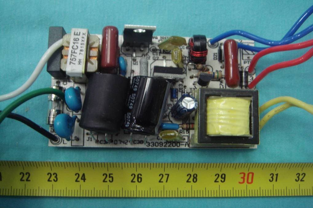
PCB-Front View PCB-Back View
Operational Description
When the power supply is connected to the electronic ballast terminal , the power is transmitted through electrical ballast terminal to the ballast. The ballast will change the power that the compact fluorescent lamp need and provide it for the compact fluorescent lamp. One 26 watt compact fluorescent lamp will consume the power that has been changed by ballas t and make light. When the power supply is connected to the blower wheel terminal , the power is transmitted through blower wheel terminal to the motor. The motor will change the power to the mechanical energy, and make the impeller rotated. When the power supply is connected to the night light terminal , the power is transmitted through night light terminal to the nigh light. The night light will consume the power and make light. Circuit Description
Schematics
Green/Verde Earth Ground/ Conexion a tierra Blue/Azul Condenser/ Condensador Earth Ground/ Conexion a tierra MOTOR/ MOTOR Terminal/Terminal Wiring diagram/ Diagrama de conexiones Black/Negro White/Blanco Power supply/ (AC120V~ 60Hz) Alimentacion Black/Negro White/Blanco Black/Negro White/Blanco Wiring box/Caja de conexiones Ballast/ Balastro Green/Verde Blue/Azul Condenser/ Condensador Earth Ground/ Conexion a tierra White/Blanco Black/Negro MOTOR/ MOTOR Terminal/Terminal Wiring diagram/ Diagrama de conexiones Earth Ground/ Conexion a tierra Night light/ Lampara de noche White/Blanco Black/NegroBlack/Negro White/Blanco White/Blanco Black/NegroBlack/Negro White/Blanco Black/Negro White/Blanco Black/Negro White/Blanco Power supply/ (AC120V~ 60Hz) Alimentacion Wiring box/Caja de conexiones Terminal/Terminal Terminal/Terminal Power supply/ (AC120V~ 60Hz) Alimentacion Power supply/ (AC120V~ 60Hz) Alimentacion Light/ Lampara (V50,V70,V80,V90,V90Q,V100,V110) (V50L,V70L,V80L,V90L,V100L,V110L D)V50L,DV70L,DV80L,DV90L,DV100L,DV110L
Test Report
FCC TEST REPORT Page 1 of 20 FCC ID : VYDV50L Applicant : Hanway Technology Co., Ltd. BNN Industrial Zone, Tongji Rd., Nantou Town, Zhongshan, Guangdong, P.R.China Equipment Under Test (EUT) : Product description : Ventilation Fan Model No. : V50L(BF50L), V70L(BF70L), V80L(BF80L), V90L(BF90L), V100L(BF100L), V110L(BF110L), DV50L(BF50DL), DV70L(BF70DL), DV80L(BF80DL), DV90L(BF90DL), DV100L(BF100DL), DV110L(BF110DL) Standards : FCC Part 18 Date of Test : Feb.29, 2008 Test Engineer : Tiger Su Reviewed By : PERPARED BY: Waltek Services (Shenzhen) Co., Ltd. 8C,West Tower, Aidi Building, No.5003 Binhe Rd, Futian District, Shenzhen518045, Guangdong, China. Tel: 86-755-83551033 Fax: 86-755-83552400 Hanway Technology Co., Ltd. FCC ID: VYDV50L Page 2 of 20 2 Contents Page 1 COVER PAGE..........................................................................................................................................................1 2 CONTENTS ..............................................................................................................................................................2 3 TEST SUMMARY....................................................................................................................................................3 4 GENERAL INFORMATION..................................................................................................................................4 4.1 CLIENT INFORMATION............................................................................................................................................4 4.2 GENERAL DESCRIPTION OF E.U.T...........................................................................................................................4 4.3 DETAILS OF E.U.T. .................................................................................................................................................4 4.4 DESCRIPTION OF SUPPORT UNITS...........................................................................................................................4 4.5 STANDARDS APPLICABLE FOR TESTING..................................................................................................................4 4.6 TEST METHODOLOGY.............................................................................................................................................4 4.7 TEST FACILITY........................................................................................................................................................5 4.8 TEST LOCATION......................................................................................................................................................5 5 EQUIPMENT USED DURING TEST ...................................................................................................................6 6 CONDUCTED EMISSION TEST ..........................................................................................................................7 6.1 TEST EQUIPMENT....................................................................................................................................................7 6.2 TEST PROCEDURE...................................................................................................................................................7 6.3 CONDUCTED TEST SETUP.......................................................................................................................................8 6.4 EUT OPERATING CONDITION.................................................................................................................................8 6.5 CONDUCTED EMISSION LIMITS...............................................................................................................................9 6.6 SPECTRUM ANALYZER............................................................................................................................................9 6.7 FREQUENCY RANGE OF MEASUREMENTS.............................................................................................................10 6.8 CONDUCTED EMISSION TEST RESULT...................................................................................................................10 6.8.1 Measurement Data .....................................................................................................................................10 7 PHOTOGRAPHS OF TESTING..........................................................................................................................13 7.1 CONDUCTED EMISSION TEST VIEW.......................................................................................................................13 8 PHOTOGRAPHS-CONSTRUCTIONAL DETAILS .........................................................................................14 8.1 EUT WITH GLASS CHIMNEY-FRONT VIEW............................................................................................................14 8.2 EUT WITH GLASS CHIMNEY-BACK VIEW..............................................................................................................14 8.3 EUT WITH GLASS CHIMNEY-OPEN VIEW..............................................................................................................15 8.4 EUT WITH PLASTIC CHIMNEY-FRONT VIEW..........................................................................................................16 8.5 EUT WITH PLASTIC CHIMNEY-BACK VIEW...........................................................................................................16 8.6 EUT WITH PLASTIC CHIMNEY-OPEN VIEW...........................................................................................................17 8.7 ELECTRONIC BALLAST -FRONT VIEW...................................................................................................................18 8.8 ELECTRONIC BALLAST -BACK VIEW.................................…
Text truncated - open the document above for the full version.
Test Setup Photos
Conducted Emission Test View
Contact Information
Applicant
JOHN LIU(PROJECT MANAGER)
Test Firm
Solid Industrial Co., Ltd.Yang Dengfang
Technical Specifications
| # | Rule Parts | Frequency Range | Power Output |
|---|---|---|---|
| 1 | 18 | 0.045 MHz - 0.045 MHz | - |
Other Applications from HANWAY TECHNOLOGY CO., LTD.
VYDQV50L
Mar 02, 2008VENTILATION FAN
Equipment Class
8CC - Part 18 Consumer Device