VYY-DM45CEQ-STubular motor
NINGBO DOOYA MECHANIC & ELECTRONIC TECHNOLOGY CO., LTD.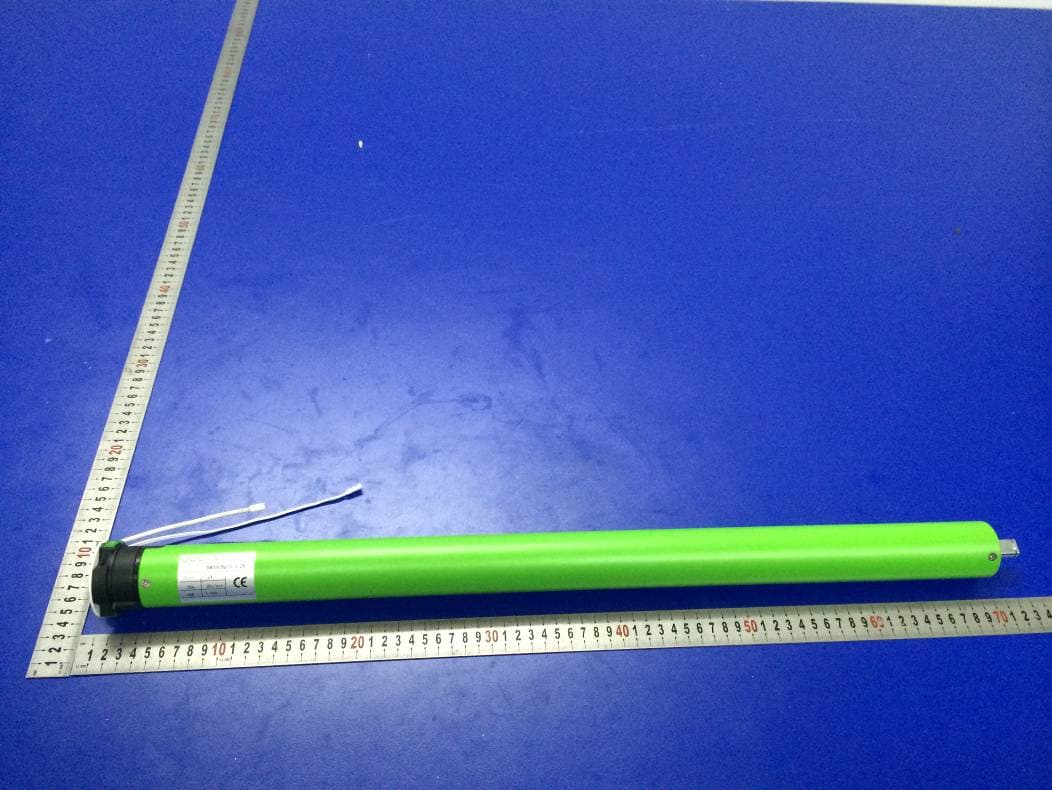
Click to zoom
Application Details
- Equipment Class
- CYY - Communications Receiver used w/Pt 15 Transmitter
- Date of Grant
- Nov 24, 2015
- Application Purpose
- Original Equipment
- Date of Application
- Nov 24, 2015
- Equipment Note
- Tubular motor
- Frequency Range
- 433.92500000 - 433.92500000
- Country
- China
Documents & Files
Document Text
Text extracted from the exhibit documents filed with the FCC. Open a document above to read the original.
Users Manual
DM45CEQ/S 3N.m 12V 433.925MHz 28RPM 1. Don’t operate motors wheuin low wltage alarm ① Motor stop running When the supply voltage is lower than 7 v, and it will restart again when the voltage is greater than 7.5V ②If the voltage is less than 10v, the motor will alarm for 10 times to prompt it needs to be charged every timewhen the motor is working. 2. Optrating: The valid interval of the emitter button is 10s,the emitter will quit the set after 10s The motor will run or beep for hint,please do the next step after the hint. 3. Set limit position: ①After the up limit and down limit setting,and the up limit down limit and third limit position are at the same location ②After limit settingwith power and memory function; ③Into the match-code status 2 minutes later, it will quit out the setting limits status automatically ④It will delete every memory and restore the factory settings 4. When the motor running without any operation, the maximum running time is 6 minutes,it will stop automatically 5 If the emitterlost,please set up again with new emitter 12V battery pole The motor can be charged by both the power adapter or the 12V supply electricity.Is that is rechargeable by solar panel or adaptor when the battery is low. Functional features: Jogging&tilt function Set electronic limit Set /delete the third limit position Low standby power Integrated radio control Setting up + add emitter +delete emitter Motor direction setting option Resistance stop function -10 85 Operating temperature Technical Dare Emission frequency(MHz) Type Rated Torque(N.m) Rated Voltage(V) Rated speed(RPM) ①Driving tube must be close-fitting with crown and drive adapter. ②Choose crown and drive adapter based on the driving tube. Drive tube Drive tube ② Runner ① Crown ③ Circlip Rechargeable Description Stroke support Tail insert bracket ②Long press the stop button for 2s,the roller blinds will move to the third limit Already set up, down limit position 2, The third limit cancel (P2StopStop) 2, Set up limit 1, Enter the limit setting mode (UpUp+Stop) Adapter or battery rod The blind run up The blind stops P2 P2 Setting button(P1) 3, Set down limit DownStop+Down 1, The third limit position setting (P2StopStop) ①After the up limit and down limit setting, you can set the third limit point between them as the half open position; Enter the limit setting mode 1 2 The motor alarms when it is working Charge the battery Motor can’t running aActivate the motor after fully charged bSet up the match code cContact the engineers for after-sales. The voltage is low in the alarm mode a,The battery is not activated. b,Theemitter is not matched. c,If press P1 button for a P2 M P2 Lithium Cell 3V Up Display Setting Channel“+” (P1+) Stop Down Channel“-” (P1-) P2 Or Dot-move Or Continuous moving + + + Enter fine-tune up limit mode + Enter fine-tune down limit mode Or + 或 + The blind run down + Or Functions that can be operated under any mode Note: After setting up the up and down limit into user mode. Note: Can not be fine-tune up/down limit position at the same time. Press 1s Run for hint x1 Press 2s Successful change the direction Press 1s Press 2s Press 2s Press 1s Run for hint x2 “Di” x3 The up limit point Confirm the Blind to stop in the up limit positio n Set up is ok Run for hint x2 “Di” x3 Set up is ok The down limit point Confirm the Blind to stop in the down limit position Press 2s The blind run down Press 1s Run for hint x1 “Di” x1 Run for hint x1 “Di” x1 Press 5sPress 5s Or Dot-move Or Continuous moving Press 1s Press 2s Press 1sPress 2s Run for hint x2 “Di” x3 Press 1sPress 2s Run for hint x2 “Di” x3 Run for hint x2 “Di” x3 Press 1s Press 1sPress 1sPress 1s Run for hint x1 “Di” x1 Run for hint x1 “Di” x1 The third limit position (any position) Any position Confirm the new up limit point Confirm the new down limit point Set up is ok Run for hint x1 “Di” x1 Run for hint x1 “Di” x1 Run for hint x1 “Di” x1 Set up is ok Press 1sPress 1sPress 1s Press 2sPress 2s Run for hint x2 “Di” x3“Di” x1 If you need to reverse the rotateon of the motor controlled by the emitter,please run the reverse of direction setting(as lists in the second point of the P1 button setting) Run for hint x1 loosen P1 Set up is ok Press 5sPress 1s Press 5sPress 1s Run for hint x1 “Di” x1 Run for hint x1 Run for hint x2 “Di” x3 Run for hint x1 Notes: Repetitive operation dot-move and continuous moving function switching cycle, under the dot-move function, according to the upor down button more than 2S release motor linkage operation. Dot-move function Continuous moving function + + Adjust the new up limit point Adjust the new down limit point PHENOMENONREASONPROCESSING METHODNUMBER Run for hint x3 Long Press P1 loosen P1 3, Restore factory settings “Di”x3 Set up is ok Long Press P1 loosen P1 2, The reverse of direction setting Run for hint x2“Di”x2 Successful change the direction Long Press P1 loosen P1 1, Activate motor for the first time Run for hint x1 “Di~~”x1 Activate is ok P2 P2 P2 P2 P2 P2 Press 1sPress 1sPress 1s Run for hint x2 “Di” x3 Run for hint x1 “Di” x1 Run for hint x1 “Di” x1 One emitter is deleted Note:With the same method,you only can delete the emitter not the emitter P2 P2 P2 P2 P2 P2 loosen P1 Press 1s Press 2sPress 2s Press 1sPress 1s Run for hint x2 “Di” x3 Run for hint x2 “Di” x3 Run for hint x1 “Di” x1 Run for hint x1 “Di” x1 Run for hint x1“Di” x1 Method two Method one Note:Emitter is the one already matched code, while emitter has not Emitter adding is ok Emitter adding is ok FCC STATEMENT 1. This device complies with Part 15 of the FCC Rules. Operation is subject to the following two conditions: (1) This device may not cause harmful interference. (2) This device must accept any interference received, including interference that may cause undesired operation. 2. Changes or modifications not expressly approved by the party responsible for compliance could void the user's authority to operate the equipment. NOTE: This equipment has been test…
Text truncated - open the document above for the full version.
Cover Letter(s)
SCS-F18: Project and Product Certification Representative Authorization Letter Page 1 of 2 Rev 5.0 775 Montague Expressway Milpitas, CA 95035 Tel: 408-526-1188 Fax: 408-526-1088 Email: [email protected] Project and Product Certification Representative Authorization Letter Reason for Amendment (current / obsolete) Revision History Approved Date From To Initial Release (obsolete) 1.0 1.0 Nov-14-2006 Revised wording (obsolete) 1.0 2.0 Sept–25-2007 Updated company template (obsolete) 2.0 3.0 Jan-31-2012 Updated letter information (obsolete) 3.0 4.0 May-23-2014 Added FCC ID field (current) 4.0 5.0 Sept 16 2014 SCS-F18: Project and Product Certification Representative Authorization Letter Page 2 of 2 Rev 5.0 NINGBO DOOYA MECHANIC & ELECTRONIC TECHNOLOGY CO., LTD. November 19, 2015 To: SIEMIC, INC. 775 Montague Expressway, Milpitas, CA 95035 USA Dear Sir/Madam, Re: Product Certification Representative Authorization Letter We, NINGBO DOOYA MECHANIC & ELECTRONIC TECHNOLOGY CO., LTD. hereby authorize SIEMIC, Inc. to act as a Certification Body for certifying for the following project(s): Tubular motor Model name: DM45CEQ/S-3/28,DM45CEQ/S-10/9 FCC ID: VYY-DM45CEQ-S Sincerely, Qiwei Zhang / Manager NINGBO DOOYA MECHANIC & ELECTRONIC TECHNOLOGY CO., LTD. Address: Loutuo industrial area, Zhenhai Ningbo, Zhejiang, China Telephone: 86-574-86571666 Fax : 86-574-86580685 E-mail: [email protected]
Cover Letter(s)
SCS-F19: Confidentiality Request Letter Page 1 of 2 Rev 4.0 775 Montague Expressway Milpitas, CA 95035 Tel: 408-526-1188 Fax: 408-526-1088 Email: [email protected] Confidentiality Request Letter Reason for Amendment (current / obsolete) Revision History Approved Date From To Initial Release (obsolete) 1.0 1.0 Nov-14-2006 Adding CFR 2.459 (obsolete) 1.0 2.0 August – 11 - 2008 Updated company template & Added text box (obsolete) 2.0 3.0 Jan-31-2012 Added IC confidentiality letter form (current) 3.0 4.0 March-26-2015 SCS-F19: Confidentiality Request Letter Page 2 of 2 Rev 4.0 NINGBO DOOYA MECHANIC & ELECTRONIC TECHNOLOGY CO., LTD. November 19, 2015 To: Federal Communications Commission Authorization and Evaluation Division 7435 Oakland Mills Road Columbia, MD Subject: Permanent Confidentiality Request for FCC ID: VYY-DM45CEQ-S We hereby request confidential treatment of information accompanying this application as outlined below: - Block Diagram - Schematics - Operational Description The above materials contain trade secrets and proprietary information not customarily released to the public. The public disclosure of these materials may be harmful to the applicant and provide unjustified benefits to its competitors. The applicant understands that pursuant to Section 0.457 & 0.459 of the Rules, disclosure of this application and all accompanying documentation will not be made before the date of the Grant for this application. Sincerely, Qiwei Zhang / Manager NINGBO DOOYA MECHANIC & ELECTRONIC TECHNOLOGY CO., LTD. Address: Loutou Industrial Area, Zhenhai, Ningbo, Zhejiang,China Telephone: 86-574-86571666 Fax : 86-574-86580685 E-mail: [email protected]
Cover Letter(s)
NINGBO DOOYA MECHANIC & ELECTRONIC TECHNOLOGY CO., LTD. Address: Loutou industrial area, Zhenhai Ningbo, Zhejiang, China Tel:86-574-86571666 Fax:86-574-86580685 Email: [email protected] November 19, 2015 To: SIEMIC, INC. 775 Montague Expressway, Milpitas, CA 95035 USA We, NINGBO DOOYA MECHANIC & ELECTRONIC TECHNOLOGY CO., LTD. hereby declare EUT (Tubular Motor ): The models of DM45CEQ/S-3/28 and DM45CEQ/S-10/9 are identical and have same stru ctu res. The only differen ce is the tooth pitch of reduction gear. Qiwei Zhang /Manager NINGBO DOOYA MECHANIC & ELECTRONIC TECHNOLOGY CO., LTD. Address: Luotou industrial area, Zhenhai Ningbo, Zhejiang, China Telephone: 86-574-86571666 Fax : 86-574-86580685 E-mail: [email protected]
External Photos
External photos: ---The End---
Internal Photos
Internal photos: ---The End---
Test Report
TRF NO. FCC Part 15 /A Page 1 of 22 Report No.: ES151110011E Ver.1.0 FCC TEST REPORT For NINGBO DOOYA MECHANIC & ELECTRONIC TECHNOLOGY CO., LTD. Tubular motor Model No.: DM45CEQ/S-3/28,DM45CEQ/S-10/9 FCC ID:VYY-DM45CEQ-S Prepared for : Ningbo Dooya Mechanic & Electronic Technology Co., Ltd. Address : Loutuo Industrial Area, Zhenhai, Ningbo, Zhejiang,China Prepared by : SHENZHEN EMTEK CO., LTD Address : Bldg 69, Majialong Industry Zone, Nanshan District, Shenzhen, Guangdong, China Tel: 0086-755-26954280 Fax: 0086-755-26954282 Report Number : ES151110011E Date of Test : November 10, 2015 to November 19, 2015 Date of Report : November 20, 2015 TRF NO. FCC Part 15 /A Page 2 of 22 Report No.: ES151110011E Ver.1.0 TABLE OF CONTENT TEST REPORT DESCRIPTION PAGE 1. SUMMARY OF TEST RESULT ...................................................................................................... 5 2. GENERAL INFORMATION ............................................................................................................. 6 2.1. Description of Device (EUT) ..................................................................................................... 6 2.2. Description of Test Facility ........................................................................................................ 6 2.3. Support Device ........................................................................................................................... 6 2.4. Measurement Uncertainty ......................................................................................................... 7 3. MEASURING DEVICE AND TEST EQUIPMENT ....................................................................... 8 3.1. For Power Line Conducted Emission ..................................................................................... 8 3.2. For Radiated Emission Measurement .................................................................................... 8 4. POWER LINE CONDUCTED EMISSION MEASUREMENT .................................................... 9 4.1. Block Diagram of Test Setup .................................................................................................... 9 4.2. Measuring Standard ................................................................................................................... 9 4.3. Power Line Conducted Emission Limits (Class B) ............................................................... 9 4.4. EUT Configuration on Measurement ...................................................................................... 9 4.5. Operating Condition of EUT ..................................................................................................... 9 4.6. Test Procedure ......................................................................................................................... 10 4.7. Measurement Results ............................................................................................................. 10 5. RADIATED EMISSION MEASUREMENT .................................................................................. 13 5.1. Block Diagram of Test ............................................................................................................. 13 5.2. Measuring Standard ................................................................................................................. 14 5.3. Radiated Emission Limits (class B) ....................................................................................... 14 5.4. EUT Configuration on Test ...................................................................................................... 14 5.5. Operating Condition of EUT ................................................................................................... 14 5.6. Test Procedure ......................................................................................................................... 14 5.7. Measuring Results ................................................................................................................... 14 6. PHOTOGRAPH OF TEST ............................................................................................................. 18 6.1. Photo of Conducted Emission Measurement ...................................................................... 18 6.2. Photo of Radiation Emission Measurement......................................................................... 19 APPENDIX I TRF NO. FCC Part 15 /A Page 3 of 22 Report No.: ES151110011E Ver.1.0 TEST REPORT DESCRIPTION Applicant : Ningbo Dooya Mechanic & Electronic Technology Co., Ltd. Manufacturer : Loutuo Industrial Area, Zhenhai, Ningbo, Zhejiang,China Trade Mark : N/A EUT : Tubular motor Model No. : DM45CEQ/S-3/28,DM45CEQ/S-10/9 Input Voltage : DC 12V Measurement Procedure Used: FCC Rules and Regulations Part 15 Subpart B Class B-2014 & ANSI C63.4-2014 The device described above is tested by SHENZHEN EMTEK CO., LTD. to determine the maximum emission levels emanating from the device and the severe levels of the device can endure and its performance criterion. The measurement results are contained in this test report and SHENZHEN EMTEK CO., LTD. is assumed full of responsibility for the accuracy and completeness of these measurements. Also, this report shows that the EUT (Equipment Under Test) is technically compliant with the FCC requirements. This report applies to above tested sample only and shall not be reproduced in part without written approval ofSHENZHEN EMTEK CO., LTD. Date of Test : November 10, 2015 to November 19, 2015 Prepared by : Jack Li/Editor Reviewer : Joe Xia/Supervisor Approved & Authorized Signer : Lisa Wang/Manager TRF NO. FCC Part 15 /A Page 4 of 22 Report No.: ES151110011E Ver.1.0 Modified History Version Report No. Revision date Summary Ver.1.0 ES151110011E \ Original Report TRF NO. FCC Part 15 /A Page 5 of 22 Report No.: ES151110011E Ver.1.0 1. SUMMARY OF TEST RESULT Emission Description of test …
Text truncated - open the document above for the full version.
Test Setup Photos
Radiated Conducted: ---The End---
Contact Information
Applicant
xiaofang Liao(MANAGER)
Test Firm
EMTEK (Shenzhen) Co., Ltd.David Lee
Technical Specifications
| # | Rule Parts | Frequency Range | Power Output |
|---|---|---|---|
| 1 | 15B | 433.925 MHz - 433.925 MHz | - |
Other Applications from NINGBO DOOYA MECHANIC & ELECTRONIC TECHNOLOGY CO., LTD.
VYYDM35TES624
Aug 17, 2026Tubular Motor
Equipment Class
DSC - Part 15 Security/Remote Control TransmitterVYYHRN71
Jun 24, 2026BLE & Thread Module
Equipment Class
DTS - Digital Transmission SystemVYY7006A02
Dec 22, 2025P-Box
Equipment Class
DSR - Part 15 Remote Control/Security Device TransceiverVYYDM4559RMSF
Oct 01, 2025Radio Tubular Motor/Radio With Manual Tubular Motor
Equipment Class
DSC - Part 15 Security/Remote Control Transmitter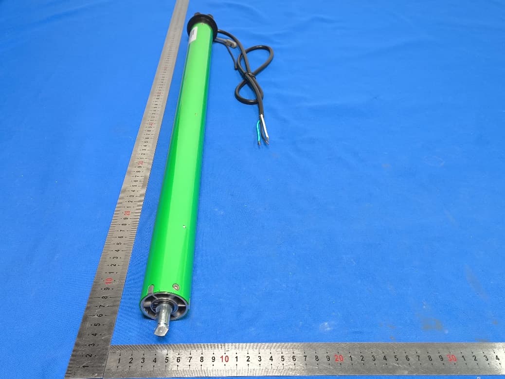
VYYDM45EAFSV0
Sep 29, 2025Electronic Tubular Motor
Equipment Class
DSC - Part 15 Security/Remote Control Transmitter