VYY-DT12TVS1214Curtain Motor
NINGBO DOOYA MECHANIC & ELECTRONIC TECHNOLOGY CO., LTD.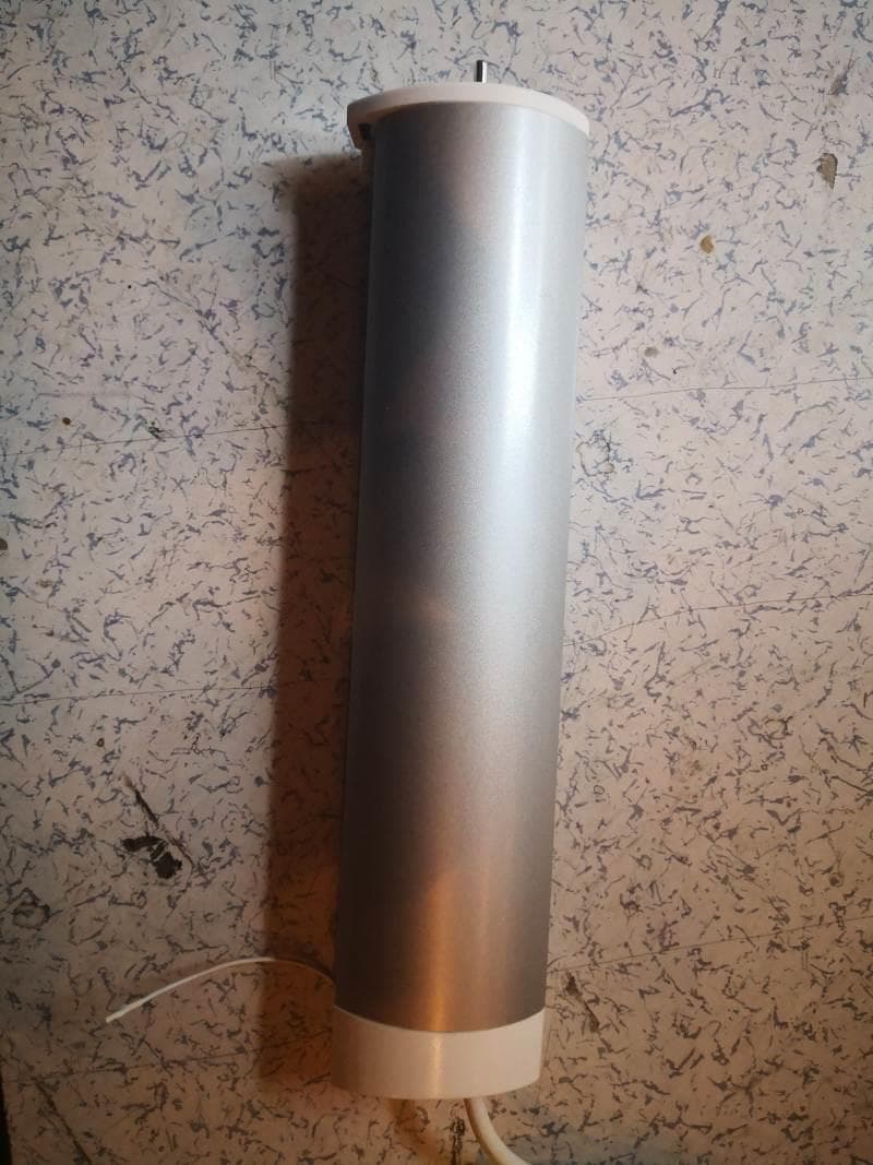
Click to zoom
Application Details
- Equipment Class
- DSR - Part 15 Remote Control/Security Device Transceiver
- Date of Grant
- Jan 05, 2020
- Application Purpose
- Original Equipment
- Date of Application
- Dec 25, 2019
- Equipment Note
- Curtain Motor
- Frequency Range
- 433.92000000 - 433.92000000
- Country
- China
Documents & Files
Document Text
Text extracted from the exhibit documents filed with the FCC. Open a document above to read the original.
Users Manual
DT12TV DC Curtain Motor Specification Version NO. : A/02 Product characteristics Technical support Pls read the instruction before assembly. a=90 o a=90 o Notes Technical support Don’t use the motorized curtain system vertically or unflatly. Assembly the motorized curtain system horizontally. 120mm 120mm Average Average Min = 35mm(1.4in) Min = 10mm(0.4in) Assembly dimension Technical support The minimum distance is decided by the wall body. The distance for brackets: 2pcs for every one-meter track one more meter for track, one more bracket. Bracket is required for the engratting track point. Inspection for motor buttons Technical support Motor function Technical support IP40 Electronic / Press the set button on the motor for 10 seconds, the indicator will flash for 7 times,then the motor will delect all data,restore factory settings.Then you can match the code and set the limit again. Electronic limit+Resistance and stop function+Limit memorized after power off+Weak electric control+Can adjust the limit p0int manually+Toutch-start+Strong electric control+RS485 function AC 100V~240V a=90 External switch interface Setting button LED light Reserve RS485 The power cord of the curtain motor can not be back thread. DT12TV Caution: This device complies with Part 15 of the FCC Rules / Innovation, Science and Economic Development Canada’s licence-exempt RSS(s). Operation is subject to the following two conditions: (1) this device may not cause harmful interference. (2) this device must accept any interference received, including interference that may cause undesired operation. L’émetteur/récepteur exempt de licence contenu dans le présent appareil est conforme aux CNR d’Innovation, Sciences et Développement économique Canada applicables aux appareils radio exempts de licence. L’exploitation est autorisée aux deux conditions suivantes : 1. L’appareil ne doit pas produire de brouillage; 2. L’appareil doit accepter tout brouillage radioélectrique subi, même si le brouillage est susceptible d’en compromettre le fonctionnement. Changes or modifications not expressly approved by the party responsible for compliance could void the user's authority to operate the equipment. This equipment has been tested and found to comply with the limits for a Class B digital device, pursuant to part 15 of the FCC Rules. These limits are designed to provide reasonable protection against harmful interference in a residential installation. This equipment generates uses and can radiate radio frequency energy and, if not installed and used in accordance with the instructions, may cause harmful interference to radio communications. However, there is no guarantee that interference will not occur in a particular installation. If this equipment does cause harmful interference to radio or television reception, which can be determined by turning the equipment off and on, the user is encouraged to try to correct the interference by one or more of the following measures: —Reorient or relocate the receiving antenna. —Increase the separation between the equipment and receiver. —Connect the equipment into an outlet on a circuit different from that to which the receiver is connected. —Consult the dealer or an experienced radio/TV technician for help. Note: The track needs to be engrafted when the length is less the required The track needs to be engrafted when inconvenient to transport S track Insert the track joint board into the two ends of track The f0llowing steps pls refer to “the assembly of rubber belt and track” Track joint board Insert the track joint bracket for one end to the track joint Fix the screws Track joint bracket The joint assembly of track Installation method Install the clip part like the referance picture and insert the track into the lower cover Slide the slip part to the other end to be flush with the head rail.Cut the other end of rubber belt with 11.5cm left Use the screw driver to place the parts like the gear into the lower cover Refer the complete lower cove in below picture Thread the rubber belt into thethe lower cover Keep this end complete Fix the cut rubber belt end with the belt fasten button Leave half teeth Seperate the lower cover and the headrail with the 11.5cm belt remaining outside the headrail.Then fix two fasten buttons on the same side of rubber belt (it is to figure out the position of the other slip part.) Install the belt fasten button and the slip part as in the picture The marked position is in the middle of the slip parts.Half of the slip parts are in the head rail as in the picture Leave one teeth between these two belt fasten button DT12 3 4 5 6 7 2 The assembly of rubber belt for curtain motor Installation method The comfirmation of profiled material dimension The length of profiled material = The total lenth of track - The cap length × 2 For example (S track): the total length of track is 2m The length of profiled material: 200cm-15cm=185cm DT82 The length of profiled material: 200cm-14cm=186cm The cap lengthThe cap length The runner are installedPlace the hook and the upper cover into the track 12cm 7.5cm DT12 7CM DT82 The DT12 and DT82 is almost the same,including the installtion,just the instructure of the upper and lower cover is different,Below takes the DT82 as the example The hook Install the belt facton button and the slip part as in the picture After one slip part installed,then thread the other end of the belt through the other lower cover These two slip parts is successfully installedSlide the runners into the track Search for the sl- ip part connected with the ends of the rubber belt Take off the screw of the slip parts and the connection bracket Push the connec- tion parts to one side Pull the slip parts slightly and seper- ate the connection part at the same time Fold the track The slip parts 5 4 3 The overlap arm which is connected to the two ends of rubber belt Track folding method Folding method for joint track (for easy transit) Installation method Assemble the …
Text truncated - open the document above for the full version.
External Photos
FCC ID: VYY-DT12TVS1214 IC: 21396-DT12TVS1214 Page 1 of 3 External Picture FCC ID: VYY-DT12TVS1214 IC: 21396-DT12TVS1214 Page 2 of 3 FCC ID: VYY-DT12TVS1214 IC: 21396-DT12TVS1214 Page 3 of 3
Internal Photos
FCC ID: VYY-DT12TVS1214 IC: 21396-DT12TVS1214 Page 1 of 5 Internal Picture FCC ID: VYY-DT12TVS1214 IC: 21396-DT12TVS1214 Page 2 of 5 FCC ID: VYY-DT12TVS1214 IC: 21396-DT12TVS1214 Page 3 of 5 FCC ID: VYY-DT12TVS1214 IC: 21396-DT12TVS1214 Page 4 of 5 Antenna FCC ID: VYY-DT12TVS1214 IC: 21396-DT12TVS1214 Page 5 of 5
Test Report
NINGBO DOOYA MECHANIC & ELECTRONIC TECHNOLOGY CO., LTD. RF TEST REPORT Report Type: FCC Part 15.231 & ISED RSS-210 RF report Model: DT12TV/S-1.2/14 REPORT NUMBER: 160801434SHA-001 ISSUE DATE: Dec 25, 2019 DOCUMENT CONTROL NUMBER: TTRF15.231_V1 © 2018 Intertek Intertek Testing Services Shanghai Building No.86, 1198 Qinzhou Road (North) Caohejing Development Zone Shanghai 200233, China Telephone: 86 21 6127 8200 www.intertek.com TEST REPORT This report is for the exclusive use of Intertek's Client and is provided pursuant to the agreement between Intertek and its Client. Intertek's responsibility and liability are limited to the terms and conditions of the agreement. Intertek assumes no liability to any party, other than to the Client in accordance with the agreement, for any loss, expense or damage occasioned by the use of this report. Only the Client is authorized to permit copying or distribution of this report and then only in its entirety. Any use of the Intertek name or one of its marks for the sale or advertisement of the tested material, product or service must first be approved in writing by Intertek. The observations and test results in this report are relevant only to the sample tested. This report by itself does not imply that the material, product, or service is or has ever been under an Intertek certification program. TTRF15.231_V1 © 2018 Intertek Page 2 of 26 Report no.: 160801434SHA-001 Applicant: NINGBO DOOYA MECHANIC & ELECTRONIC TECHNOLOGY CO., LTD. No.168 Shengguang Road, Luotuo, Zhenhai, Ningbo, ZHEJIANG, China Manufacturer: NINGBO DOOYA MECHANIC & ELECTRONIC TECHNOLOGY CO., LTD. No.168 Shengguang Road, Luotuo, Zhenhai, Ningbo, ZHEJIANG, China FCC ID: VYY-DT12TVS1214 IC: 21396-DT12TVS1214 SUMMARY: The equipment complies with the requirements according to the following standard(s) or Specification: 47CFR Part 15 (2018): Radio Frequency Devices (Subpart C) ANSI C63.10 (2013): American National Standard of Procedures for Compliance Testing of Unlicensed Wireless Devices RSS-210 Issue 9 (August 2016): Licence-exempt Radio Apparatus (All Frequency Bands): Category I Equipment RSS-Gen Issue 5 (April 2018): General Requirements for Compliance of Radio Apparatus PREPARED BY: REVIEWED BY: Project Engineer Stephanie Zhang Reviewer Wakeyou Wang Report No.: 160801434SHA-001 TEST REPORT TTRF15.231_V1 © 2018 Intertek Page 3 of 26 Content REVISION HISTORY................................................................................................................................................ 4 MEASUREMENT RESULT SUMMARY ..................................................................................................................... 5 1 GENERAL INFORMATION ............................................................................................................................. 6 1.1 DESCRIPTION OF EQUIPMENT UNDER TEST (EUT) ..................................................................................................... 6 1.2 TECHNICAL SPECIFICATION .................................................................................................................................... 6 1.3 DESCRIPTION OF TEST FACILITY .............................................................................................................................. 7 2 TEST SPECIFICATIONS ................................................................................................................................... 8 2.1 STANDARDS OR SPECIFICATION ............................................................................................................................... 8 2.2 MODE OF OPERATION DURING THE TEST ................................................................................................................... 8 2.3 TEST SOFTWARE LIST ............................................................................................................................................ 8 2.4 TEST PERIPHERALS LIST ......................................................................................................................................... 8 2.5 TEST ENVIRONMENT CONDITION: ............................................................................................................................ 9 2.6 INSTRUMENT LIST .............................................................................................................................................. 10 2.7 MEASUREMENT UNCERTAINTY ............................................................................................................................. 11 3 FUNDAMENTAL & SPURIOUS EMISSION & RESTRICT BAND RADIATED EMISSION ...................................... 12 3.1 LIMIT .............................................................................................................................................................. 12 3.2 MEASUREMENT PROCEDURE ............................................................................................................................... 13 3.3 TEST CONFIGURATION ........................................................................................................................................ 14 3.4 TEST RESULTS OF RADIATED EMISSIONS ................................................................................................................. 16 4 POWER LINE CONDUCTED EMISSION ......................................................................................................... 18 4.1 LIMIT .............................................................................................................................................................. 18 4.2 TEST CONFIGURATION ........................................................................................................................................ 18 4.3 MEASUREMENT PROCEDURE ............................................................................................................................... 19 4.…
Text truncated - open the document above for the full version.
Test Setup Photos
FCC ID: VYY-DT12TVS1214 IC: 21396-DT12TVS1214 Page 1 of 4 Test Setup FCC ID: VYY-DT12TVS1214 IC: 21396-DT12TVS1214 Page 2 of 4 1. Radiated Emission Lower than 1GHz FCC ID: VYY-DT12TVS1214 IC: 21396-DT12TVS1214 Page 3 of 4 Higher than 1GHz FCC ID: VYY-DT12TVS1214 IC: 21396-DT12TVS1214 Page 4 of 4 2. Conducted Emission
Contact Information
Applicant
xiaofang Liao(MANAGER)
Technical Contact
Intertek Testing Services Limited ShanghaiWakeyou Wang
[email protected]86 21 61278265
Building No.86, 1198 Qinzhou Road(North) · Shanghai · China
Test Firm
Intertek Testing Services ShanghaiLeah Xu
[email protected]+86 21 61278200
Technical Specifications
| # | Rule Parts | Frequency Range | Power Output |
|---|---|---|---|
| 1 | 15.231 | 433.92 MHz - 433.92 MHz | - |
Other Applications from NINGBO DOOYA MECHANIC & ELECTRONIC TECHNOLOGY CO., LTD.
VYYDM35TES624
Aug 17, 2026Tubular Motor
Equipment Class
DSC - Part 15 Security/Remote Control TransmitterVYYHRN71
Jun 24, 2026BLE & Thread Module
Equipment Class
DTS - Digital Transmission SystemVYY7006A02
Dec 22, 2025P-Box
Equipment Class
DSR - Part 15 Remote Control/Security Device TransceiverVYYDM4559RMSF
Oct 01, 2025Radio Tubular Motor/Radio With Manual Tubular Motor
Equipment Class
DSC - Part 15 Security/Remote Control Transmitter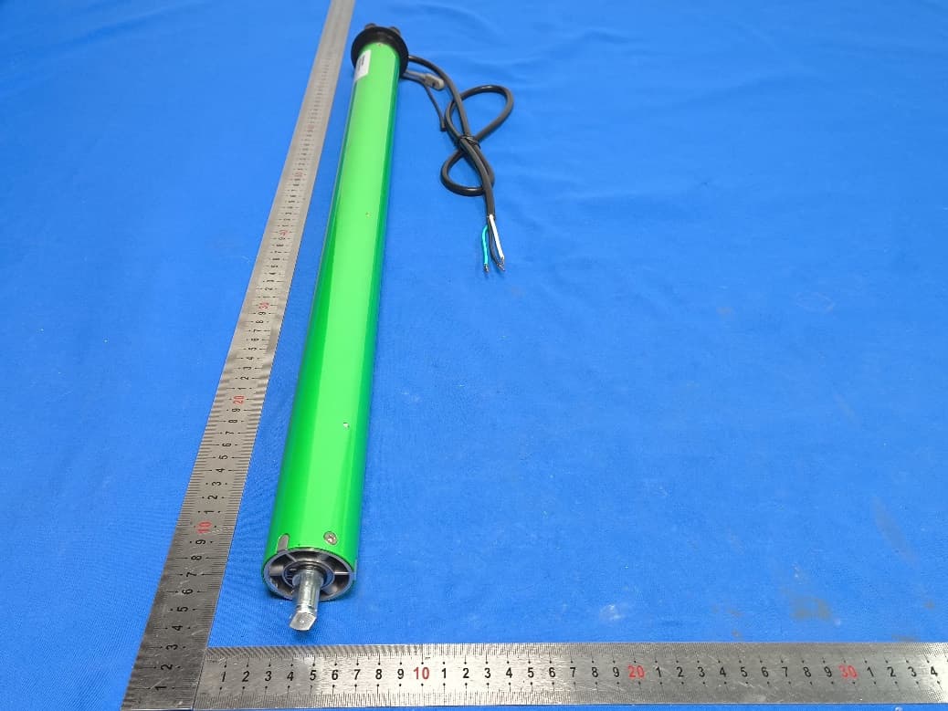
VYYDM45EAFSV0
Sep 29, 2025Electronic Tubular Motor
Equipment Class
DSC - Part 15 Security/Remote Control Transmitter