VYY1554EV00Connector Mini Bridge
NINGBO DOOYA MECHANIC & ELECTRONIC TECHNOLOGY CO., LTD.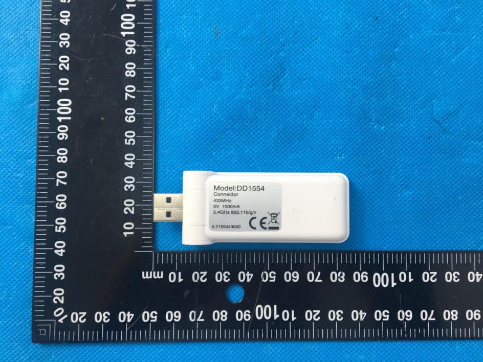
Click to zoom
Application Details
- Equipment Class
- DSR - Part 15 Remote Control/Security Device Transceiver
- Date of Grant
- Jan 14, 2024
- Application Purpose
- Original Equipment
- Date of Application
- Jan 14, 2024
- Equipment Note
- Connector Mini Bridge
- Frequency Range
- 433.92000000 - 433.92000000
- Country
- China
Documents & Files
Document Text
Text extracted from the exhibit documents filed with the FCC. Open a document above to read the original.
Users Manual
RF exposure statement This equipment complies with the FCC RF radiation exposure limits set forth for an uncontrolled environment. This equipment should be installed and operated with a minimum distance of 20cm between the radiator and any part of your body. This equipment meets the exemption from the routine evaluation limits in section 2.5 of RSS-102. It should be installed and operated with a minimum distance of 20cm between the radiator and any part of your body. Cet équipement est conforme à l'exemption des limites d'évaluation habituelle de la section 2.5 de la norme RSS-102. Il doit être installé et utilisé à une distance minimale de 20 cm entre le radiateur et toute partie de votre corps. FCC Warning This device complies with Part 15 of the FCC Rules. Operation is subject to the following two conditions: (1) This device may not cause harmful interference, and (2) this device must accept any interference received, including interference that may cause undesired operation. Note: This equipment has been tested and found to comply with the limits for a Class B digital device, pursuant to part 15 of the FCC Rules. These limits are designed to provide reasonable protection against harmful interference in a residential installation. This equipment generates, uses and can radiate radio frequency energy and, if not installed and used in accordance with the instructions, may cause harmful interference to radio communications. However, there is no guarantee that interference will not occur in a particular installation. If this equipment does cause harmful interference to radio or television reception, which can be determined by turning the equipment off and on, the user is encouraged to try to correct the interference by one or more of the following measures: —Reorient or relocate the receiving antenna. —Increase the separation between the equipment and receiver. —Connect the equipment into an outlet on a circuit different from that to which the receiver is connected. —Consult the dealer or an experienced radio/TV technician for help. NOTE 2: Any changes or modifications to this unit not expressly approved by the party responsible for compliance could void the user's authority to operate the equipment. IC WARNING This device contains licence-exempt transmitter(s) that comply with Innovation, Science and Economic Development Canada’s licence-exempt RSS(s). Operation is subject to the following two conditions: (1) This device may not cause interference. (2) This device must accept any interference, including interference that may cause undesired operation of the device. L’émetteur/récepteur exempt de licence contenu dans le présent appareil est conforme aux CNR d’Innovation, Sciences et Développement économique Canada applicables aux appareils radio exempts de licence. L’exploitation est autorisée aux deux conditions suivantes: 1. L’appareil ne doit pas produire de brouillage; 2. L’appareil doit accepter tout brouillage radioélectrique subi, même si le brouillage est susceptible d’en compromettre le fonctionnement.
External Photos
Reference No.: WTN23X10214841W001 Page 2 of 8 Waltek Testing Group (Shenzhen) Co., Ltd. Http://www.waltek.com.cn EXHIBIT 2 - EUT EXTERNAL PHOTOGRAPHS EUT View 1 EUT View 2 Reference No.: WTN23X10214841W001 Page 3 of 8 Waltek Testing Group (Shenzhen) Co., Ltd. Http://www.waltek.com.cn EUT View 3 EUT View 4 Reference No.: WTN23X10214841W001 Page 4 of 8 Waltek Testing Group (Shenzhen) Co., Ltd. Http://www.waltek.com.cn EUT View 5 EUT View 6
ID Label/Location Info
Reference No.: WTN23X10214841W001 Page 1 of 8 Waltek Testing Group (Shenzhen) Co., Ltd. Http://www.waltek.com.cn ANNEX EXHIBIT 1 - PRODUCT LABELING Proposed FCC ID Label Format Specifications: The label shall be securely affixed to a permanently attached part of the device, in a location where it is visible or easily accessible to the user, and shall not be readily detachable. The label shall be sufficiently durable to remain fully legible and intact on the device in all normal conditions of use throughout the device’s expected lifetime. Proposed Label Location on EUT FCC ID Label Location
Internal Photos
Reference No.: WTN23X10214841W001 Page 5 of 10 Waltek Testing Group (Shenzhen) Co., Ltd. Http://www.waltek.com.cn EXHIBIT 3 - EUT INTERNAL PHOTOGRAPHS EUT Housing and Board View 1 Solder Board-Component View 1 Reference No.: WTN23X10214841W001 Page 6 of 10 Waltek Testing Group (Shenzhen) Co., Ltd. Http://www.waltek.com.cn Solder Board-Component View 2 Solder Board-Component View 3 Reference No.: WTN23X10214841W001 Page 7 of 10 Waltek Testing Group (Shenzhen) Co., Ltd. Http://www.waltek.com.cn Solder Board-Component View 4 Solder Board-Component View 5 Reference No.: WTN23X10214841W001 Page 8 of 10 Waltek Testing Group (Shenzhen) Co., Ltd. Http://www.waltek.com.cn Solder Board-Component View 6 Antenna View Antenna
RF Exposure Info
1. RF Exposure Requirements 1.1 General Information Client Information Applicant: Ningbo Dooya Mechanic & Electronic Technology Co., Ltd Address of applicant: NO.168 shengguang road Luotuo street Zhenhai District Ningbo, P.R.China Manufacturer: The same as Applicant Address of manufacturer: The same as Applicant General Description of EUT: Product Name: Connector Mini Bridge Trade Name: / Model No.: DD1554E Adding Model(s): / Rated Voltage: DC 5V Power Adaptor : / Power Adapter Model: / FCC ID: VYY1554EV00 Equipment Type: Mobile device Technical Characteristics of EUT: Frequency Range: 433.92 MHz Max. Field Strength: 433.92MHz: 87.20dBuV/m(3m) Data Rate: / Modulation: FSK Antenna Type: Integral Antenna Antenna Gain: 0dBi 1.2 RF Exposure Exemption According to §1.1307(b)(3) and KDB 447498 D04 Interim General RF Exposure Guidance v01, system operating under the provisions of this section shall be operating in a manner that the public is not exposed to radio frequency energy level in excess limit for maximum permissible exposure. Option A: FCC Rule Part 1.1307 (b)(3)(i)(A):The available maximum time-averaged power is no more than 1mW, regardless of separation distance. Option B: FCC Rule Part 1.1307 (b)(3)(i)(B): The available maximum time-averaged power or effective radiated power (ERP), whichever is greater, is less than or equal to the threshold P th (mW) described in the following formula. P th is given by: Option C: FCC Rule Part 1.1307 (b)(3)(i)(C): The minimum separation distance (R in meters) from the body of a nearby person for the frequency (f in MHz) at which the source operates, the ERP (watts) is no more than the calculated value prescribed for that frequency. R must be at least λ/2π, where λ is the free-space operating wavelength in meters. Single RF Sources Subject to Routine Environmental Evaluation RF Source frequency (MHz) Threshold ERP (watts) 0.3-1.34 1,920 R 2 1.34-30 3,450 R 2 /f 2 30-300 3.83 R 2 300-1,500 0.0128 R 2 f 1,500-100,000 19.2R 2 For Multiple RF sources: FCC Rule Part 1.1307(b)(3)(ii): (A) The available maximum time-averaged power of each source is no more than 1 mW and there is a separation distance of two centimeters between any portion of a radiating structure operating and the nearest portion of any other radiating structure in the same device, except if the sum of multiple sources is less than 1 mW during the time-averaging period, in which case they may be treated as a single source (separation is not required). (B) In the case of fixed RF sources operating in the same time-averaging period, or of multiple mobile or portable RF sources within a device operating in the same time averaging period, if the sum of the fractional contributions to the applicable thresholds is less than or equal to 1 as indicated in the following equation. 1.3 Calculated Result Radio Access Technology Prediction Frequency Max. Field Strength Antenna Gain Output Power Tune-Up Power ERP (MHz) (dBuV/m) (dBi) (dBm) (dBm) (dBm) SRD 433.92 87.20 0 -8.06 -8.00 -10.15 Wi-Fi 2412 -- 3.26 17.56 18.00 19.11 Bluetooth (Low Energy) 2402 -- 3.26 8.52 9.00 10.11 Note: Wi-Fi Data refer to the Wi-Fi & Bluetooth Internet of Things Module (FCC ID: 2AC7Z-ESPC3WROOM; issue date: 05/13/2022) Frequency Option Min. Distance Max. Power Exposure Limit Ratio Result (MHz) (cm) (dBm) (mW) (mW) Pass/Fail 433.92 C 20.00 -10.15 0.10 222.17 0.01 Pass 2412 C 20.00 19.11 81.47 768.00 0.11 Pass 2402 C 20.00 10.11 10.26 768.00 0.01 Pass Note: 1. EIRP= E-104.8+20logD; Output Power=EIRP- Antenna Gain; ERP=EIRP-2.15dB 2. Option A, B and C refers as clause 1.2. 3. For option B, Max (time-averaged power, effective radiated power (ERP)) converts to Max. Power. For option C, ERP converts to Max. Power; 4. For option B, P th (mW) converts to Exposure Limit (mW); For option C, ERP (W) converts to Exposure Limit (mW). 5. Ratio= Tune-Up ERP (mW)/ Exposure Limit (mW) Mode for Simultaneous Multi-band Transmission: Radio Access Technology Ratio 1 Ratio 2 Simultaneous Ratio Limit Result Pass/Fail SRD+ Wi-Fi 0.01 0.08 0.09 1 Pass SRD+ Bluetooth 0.01 0.01 0.02 1 Pass Note: Wi-Fi and Bluetooth is the use the same antenna cannot simultaneous transmission. Result: Pass
Test Report
SRD Technical Specification © 2017 Intertek
Test Setup Photos
Reference No.: WTN23X10214841W001 Page 7 of 8 Waltek Testing Group (Shenzhen) Co., Ltd. Http://www.waltek.com.cn EXHIBIT 4 - TEST SETUP PHOTOGRAPHS Conducted Emission Test Setup Radiation Emission Test Setup (Below 30MHz) Reference No.: WTN23X10214841W001 Page 8 of 8 Waltek Testing Group (Shenzhen) Co., Ltd. Http://www.waltek.com.cn Radiation Emission Test Setup (30MHz to 1GHz) Radiation Emission Test Setup (1GHz to 18GHz) ***** END OF REPORT *****
Contact Information
Applicant
xiaofang Liao(MANAGER)
Test Firm
Waltek Testing Group (Shenzhen) Co., Ltd.Jandy So
Technical Specifications
| # | Rule Parts | Frequency Range | Power Output |
|---|---|---|---|
| 1 | 15.231 | 433.92 MHz - 433.92 MHz | - |
Other Applications from NINGBO DOOYA MECHANIC & ELECTRONIC TECHNOLOGY CO., LTD.
VYYDM35TES624
Aug 17, 2026Tubular Motor
Equipment Class
DSC - Part 15 Security/Remote Control TransmitterVYYHRN71
Jun 24, 2026BLE & Thread Module
Equipment Class
DTS - Digital Transmission SystemVYY7006A02
Dec 22, 2025P-Box
Equipment Class
DSR - Part 15 Remote Control/Security Device TransceiverVYYDM4559RMSF
Oct 01, 2025Radio Tubular Motor/Radio With Manual Tubular Motor
Equipment Class
DSC - Part 15 Security/Remote Control Transmitter
VYYDM45EAFSV0
Sep 29, 2025Electronic Tubular Motor
Equipment Class
DSC - Part 15 Security/Remote Control Transmitter