VZI00220AVIATION SERVICES TRANSPONDER TRANSMITTER
Trig Avionics Limited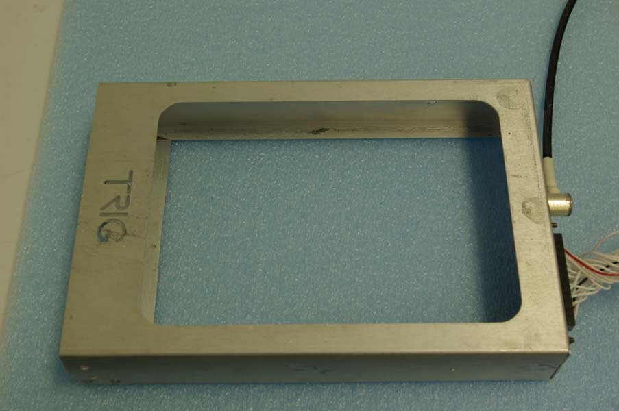
Click to zoom
Application Details
- Equipment Class
- TNB - Licensed Non-Broadcast Station Transmitter
- Date of Grant
- Feb 18, 2008
- Application Purpose
- Original Equipment
- Date of Application
- Feb 18, 2008
- Equipment Note
- AVIATION SERVICES TRANSPONDER TRANSMITTER
- Frequency Range
- 1090.00000000 - 1090.00000000
- Company
- Trig Avionics Limited
- Country
- United Kingdom
Documents & Files
Document Text
Text extracted from the exhibit documents filed with the FCC. Open a document above to read the original.
Users Manual
TT31 Mode S Transponder Operating Manual 00454-00-AA 1 September 2006 Trig Avionics Limited Heriot Watt Research Park Riccarton, Currie EH14 4AP Scotland, UK © Copyright 2006 Front Panel Display The display shows the operating mode of the transponder, the reported pressure altitude, and the current squawk code and Flight ID. The reply indicator is active when the transponder replies to interrogations. The pressure altitude is displayed as a Flight Level, which is the pressure altitude in hundreds of feet. When non-standard atmospheric conditions apply, this may not match the altimeter indicated altitude, but will be correctly displayed by the ATC radar. Mode Selector Knob The left hand knob controls the power to the transponder and the operating mode. OFF Power is removed from the transponder. SBY The transponder is on, but will not reply to any interrogations. GND The transponder will respond to Mode S ground interrogations from surface movement radar. ON The transponder will respond to all interrogations, but altitude reporting is suppressed. ALT The transponder will respond to all interrogations. When airborne, the transponder should always be set to ALT unless otherwise directed by Air Traffic Control. When you are taxiing on the ground, the transponder should be set to GND unless your installation includes a gear squat switch. Aircraft installations that include a gear squat switch will automatically select GND on landing. Push Buttons IDENT Press the IDENT button when ATC instructs you to “Ident” or “Squawk Ident”. This activates the SPI pulse in the transponder replies for 18 seconds. IDENT will appear in the display. FUNC Pressing the FUNC button provides access to the flight timer, stopwatch and altitude monitor function. VFR Pressing the VFR button sets the transponder to the pre- programmed conspicuity code. Pressing the button again restores the previous squawk code. FLT/SQ Pressing FLT/SQ alternates the primary display between squawk code and Flight ID. ENT The ENT button enters a digit in the code selector. BACK The BACK button goes back to the previous digit in the code selector. Code Selector Knob The right hand knob is used to set squawk codes and the Flight ID. The FLT/SQ button selects which will be updated. Turning the knob will highlight the first digit on the display, and the digit can be changed as required. Press the ENT button to advance to the next digit. When ENT is pressed on the last digit, the new squawk code or Flight ID will replace the previous value. If the code entry is not completed within 7 seconds, the changes are ignored and the previous code restored. 1200 VFR code in the USA 7000 VFR code commonly used in Europe. 7500 Hijack code 7600 Loss of communications 7700 Emergency code The Flight ID should correspond to the aircraft call sign entered on your flight plan. If no flight plan is active, the aircraft registration should be used as your Flight ID. Use only letters and digits. If the Flight ID is less than 8 characters long, entering a blank character will end it. Flight Timer The Flight Timer records the time for which the transponder has been powered on and operating in flight mode – either ON or ALT. Press the FUNC button to display the Flight Timer. Stopwatch The stopwatch can be used as a convenient timer. Press the FUNC button to display the stopwatch. Pressing ENT will reset and start the timer. Pressing ENT again will stop the timer. Altitude Monitor The Altitude Monitor activates an audio annunciator or annunciator light (depending on installation) when the aircraft pressure altitude differs from the selected altitude by more than 200 feet. Press the FUNC button to display the altitude monitor enable screen. Pressing ENT toggles the altitude monitor at the current altitude. When altitude monitoring is in use, a small deviation pointer appears adjacent to the altitude display on the transponder. Fault Annunciation If the transponder detects an internal failure, the screen will indicate FAULT and a brief statement of the problem. No replies will be made to interrogations when a fault is detected. Configuration Mode The system is configured when it is first installed by your avionics supplier. Configuration items include the Mode S aircraft address, the aircraft category, and the pre-programmed values for VFR squawk code. To view or change these settings you must use Configuration Mode. Do not use Configuration Mode in flight. Check with your avionics installer before changing the configuration. To enter configuration mode, hold down the FUNC button whilst switching on the transponder. Configuration items can be changed using the Code Knob and the ENT and BACK buttons. Pressing FUNC advances to the next configuration item. When configuration is complete, switch the transponder off. When it is switched back on the transponder will use the new configuration. Low Temperature Operation The TT31 is certified to operate correctly down to -20C, but at low temperatures the display may be impaired. On a cold day you may need to wait for the cockpit to warm up to ensure normal operation. Trig Avionics Limited Building 4, Heriot Watt Research Park Riccarton, Currie EH14 4AP, UK Tel: +44 (0)131 449 8810 Fax: +44 (0)131 449 8811 [email protected] www.trig-avionics.com
Cover Letter(s)
February 17, 2008 Timco Engineering Inc. 849 NW State Road 45 Newberry, FL 32669 Applicant: Trig Avionics Limited Heriot Watt Research Park, Riccarton Currie EH14 4AP United Kingdom Equipment: FCC ID: VZI00220 CORES number: 0017 3590 84 FCC Rules: Part 87 Hello. Please find copy of the request and response below. Thank you for this application for a Grant of Certification. Per our telephone conversation, we will hold this job awaiting the FAA approval letter. Thank you. Response 1. The FAA letter of concurrence has been uploaded to your site for review and acceptance. Should you require any further information, please contact the undersigned. Thank you for your consideration in this matter. Sincerely, Scot Rogers Rogers Labs, Inc. Enclosures ROGERS LABS, INC. 4405 West 259 th Terrace Louisburg, KS 66053 Phone / Fax (913) 837-3214
Cover Letter(s)
January 24, 2008 Federal Communications Commission Equipment Approval Services Post Office Box 358315 Pittsburgh, Pennsylvania 15215-5315 To Whom It May Concern: Please be advised that Trig Avionics Limited has authorized Scot Rogers of Rogers Labs, Inc. to act on behalf in all matters relating to application for equipment authorization, including the signing of all documents relating to these matters and submittals. All acts carried out by Rogers Labs, Inc. on our behalf shall have the same effects as our own. Rogers Labs, Inc. is authorized to receive and exchange data between our company and the Commission. This Authorization is made pursuant to Paragraph 2.911 of FCC Rules CFR 47. This Authorization is in effect until otherwise notified in writing. Andrew Davis CEO Trig Avionics Limited
Cover Letter(s)
February 8, 2008 Timco Engineering Inc. 849 NW State Road 45 Newberry, FL 32669 Applicant: Trig Avionics Limited Heriot Watt Research Park Riccarton Currie EH14 4AP United Kingdom Re: Confidentiality for submittal information regarding FCC ID number VZI00220 PRODUCT: Aviation Transponder operated under part 87 Dear Sirs: Trig Avionics Limited requests that the material in the Schematics, Operational Description, block diagram, and parts lists be withheld from public disclosure in accordance with Section 0.459 of the Commissions Rules, 47 C.F.R. 0.459, following grant of the application. In support of this request, Trig Avionics Limited submits the following: CONFIDENTIAL FILES Schematics Conf Schem 00220 1.pdf, Conf Schem 00220 2.pdf Schematics Conf Schem 00220 3.pdf, Conf Schem 00220 4.pdf Block diagram Conf BlkDia 00220.pdf Operational Description Conf OpDes 00220.pdf Parts Lists Conf PartList 00220 1.pdf, Conf PartList 00220 2.pdf, Conf PartList 00220 3.pdf 1. Identification of the specific information for which confidential treatment is sought: The materials set fourth in the Operational Description, block diagram, parts list, and Schematics, which are segregated, from the non-confidential exhibits of the application, are those for which confidentiality is sought. 2. Identification of the Commission proceeding in which the information was submitted or a description of the circumstances giving rise to the submission: The proceeding is that involving the application for equipment authorization (certification) under FCC ID No: VZI00220 3. Explanation of the degree to which the information is commercial or financial, or contains a trade secret or is privileged: ROGERS LABS, INC. 4405 West 259 th Terrace Louisburg, KS 66053 This material includes a detailed theory of operation, circuit diagrams, and schematic. As such, this material is treated as highly confidential business information. 4. Explanation of the degree to which the information concerns a service that is subject to competition: The material for which confidentiality is sought is employed in the design and manufacture of this transmitting equipment that is offered on a highly competitive basis. Customers for this equipment have a variety of competing sources. 5. Explanation of how disclosure of the information could result in substantial competitive harm: Disclosure would, in effect, give away the fruits of the labors of Trig Avionics Limited’s engineering personnel, who have designed the equipment and the manufacturing process. Disclosure would also offer competitors additional unwarranted insight into the state of the product development, thereby allowing competitors an advantage, not available to Trig Avionics Limited 6. Identification of any measures taken by the submitting party to prevent unauthorized disclosure: The information for which confidential treatment is sought is kept confidential by Trig Avionics Limited and not made available to third parties except pursuant to non-disclosure agreements. 7. Identification of whether the information is available to the public and the extent of any previous disclosure of the information to third parties: To the knowledge of those preparing this application, the information has not been disclosed publicly heretofore. While the general theory of operation of this equipment has been the subject of numerous disclosures in industry and standards groups as well as in rule making proceedings of the FCC, the protection sought is narrowly drawn and pertains to certain specific implementations of this radio technology. 8. Justification of the period during which the submitting party asserts that the material should not be available for public disclosure: This material should not be disclosed for at least 25 years. While improvements in design are made relatively frequently, disclosure of the design information would lead to insights into both design and manufacturing techniques that could have an adverse competitive effect for many years to come. This equipment is designed for commercial, industrial, and governmental applications. As such, unlike most consumer equipment, this equipment could be used for more than a decade in some cases. As such, it is important that the design not be made available to unauthorized persons who might attempt to use knowledge of the design to compromise the applications for which the equipment will be employed. Should you require any further information, please contact the undersigned. Thank you for your consideration in this matter. Sincerely, Scot Rogers
Cover Letter(s)
February 8, 2008 Office of Engineering and Technology Federal Communications Commission Columbia, MD 21046 Applicant: Trig Avionics Limited Equipment: FCC ID: VZI00220 Heriot Watt Research Park, Riccarton CORES number: 0017 3590 84 Currie EH14 4AP United Kingdom FCC Rules: Part 87 Re: Short-term Confidentiality request for submittal information regarding FCC ID number VZI00220 Product: Aviation Transponder operating under part 87 Dear Sirs: Trig Avionics Limited requests that the following information be withheld from public disclosure until 45 days after the Grant of Equipment Authorization in accordance with DA- 04-1705 of the Commission’s public notice. Short term confidential files External Photos ExtPho 00220.pdf Internal Photos IntPho 00220.pdf Test Setup Photos Tsup 00220.pdf User Manual UserMan 00220.pdf Permanent Confidential files Schematics Conf Schem 00220 1.pdf, Conf Schem 00220 2.pdf Schematics Conf Schem 00220 3.pdf, Conf Schem 00220 4.pdf Block diagram Conf BlkDia 00220.pdf Operational Description Conf OpDes 00220.pdf Parts Lists Conf PartList 00220 1.pdf, Conf PartList 00220 2.pdf, Conf PartList 00220 3.pdf, Should you require any further information, please contact the undersigned. Thank you for your consideration in this matter. Sincerely, Scot Rogers ROGERS LABS, INC. 4405 West 259 th Terrace Louisburg, KS 66053
Cover Letter(s)
February 8, 2008 Timco Engineering Inc. Federal Communications Commission 849 NW State Road 45 Equipment Approval Services Newberry, FL 32669 P.O. Box 35815, Pittsburgh, PA 15251-3315 Applicant: Trig Avionics Limited Equipment: FCC ID: VZI00220 Heriot Watt Research Park, Riccarton CORES number: 0017 3590 84 Currie EH14 4AP United Kingdom FCC Rules: Part 87 Gentlemen: The 731 form and application have been electronically submitted and any attachments will be up loaded to your web site to be used in obtaining a grant of certification. Confidentiality is requested as outlined below. Short-term Pursuant to DA 04-1705 of the Commission’s pubic notice, we request short-term confidential treatment for the following information until 45 days after the Grant Date of Equipment Authorization in order to ensure sensitive business information remains confidential until the actual marketing of the device: External Photos ExtPho 00220.pdf Internal Photos IntPho 00220.pdf Test Setup Photos Tsup 00220.pdf User Manual UserMan 00220.pdf Permanent Trig Avionics Limited requests that the material in the Parts List, Schematics, block diagram, and Operational Description be withheld from public disclosure in accordance with Section 0.459 of the Commissions Rules, 47 C.F.R. 0.459, following grant of the application. It is requested that the information contained in the operational description, block diagram, parts list, and schematics of the application be held confidential per Section 0.459. A statement of confidentiality will be attached with the application at the time of submittal. Schematics Conf Schem 00220 1.pdf, Conf Schem 00220 2.pdf Schematics Conf Schem 00220 3.pdf, Conf Schem 00220 4.pdf Block diagram Conf BlkDia 00220.pdf Operational Description Conf OpDes 00220.pdf Parts Lists Conf PartList 00220 1.pdf, Conf PartList 00220 2.pdf, Conf PartList 00220 3.pdf, Should you require any further information, please contact the undersigned. Thank you for your consideration in this matter. Sincerely, Scot Rogers Rogers Labs, Inc. Enclosures ROGERS LABS, INC. 4405 West 259 th Terrace Louisburg, KS 66053 Phone / Fax (913) 837-3214
External Photos
Rogers Labs, Inc. Trig Avionics Limited 4405 West 259 th Terrace Model: 00220 SN: 2307-00305 Louisburg, KS 66053 Test #: 080123 FCC ID#: VZI00220 Phone/Fax: (913) 837-3214 Test to: FCC Parts 2, 15 and 87 Page 1 of 2 Revsion 1 File ExtPho 00220 Date: February 3, 2008 External photographs of equipment under test Rogers Labs, Inc. Trig Avionics Limited 4405 West 259 th Terrace Model: 00220 SN: 2307-00305 Louisburg, KS 66053 Test #: 080123 FCC ID#: VZI00220 Phone/Fax: (913) 837-3214 Test to: FCC Parts 2, 15 and 87 Page 2 of 2 Revsion 1 File ExtPho 00220 Date: February 3, 2008 Mounting hardware
ID Label/Location Info
Rogers Labs, Inc. Trig Avionics Limited 4405 West 259 th Terrace Model: 00220 SN: 2307-00305 Louisburg, KS 66053 Test #: 080123 FCC ID#: VZI00220 Phone/Fax: (913) 837-3214 Test to: FCC Parts 2, 15 and 87 Page 1 of 1 Revision 1 File LabelSmpl 00220 Date: February 3, 2008 FCC/IC ID label and location
Internal Photos
Rogers Labs, Inc. Trig Avionics Limited 4405 West 259 th Terrace Model: 00220 SN: 2307-00305 Louisburg, KS 66053 Test #: 080123 FCC ID#: VZI00220 Phone/Fax: (913) 837-3214 Test to: FCC Parts 2, 15 and 87 Page 1 of 3 Revsion 1 File IntPho 00220 Date: February 3, 2008 Internal Photographs Inside case with covers Rogers Labs, Inc. Trig Avionics Limited 4405 West 259 th Terrace Model: 00220 SN: 2307-00305 Louisburg, KS 66053 Test #: 080123 FCC ID#: VZI00220 Phone/Fax: (913) 837-3214 Test to: FCC Parts 2, 15 and 87 Page 2 of 3 Revsion 1 File IntPho 00220 Date: February 3, 2008 Receiver PCB Rogers Labs, Inc. Trig Avionics Limited 4405 West 259 th Terrace Model: 00220 SN: 2307-00305 Louisburg, KS 66053 Test #: 080123 FCC ID#: VZI00220 Phone/Fax: (913) 837-3214 Test to: FCC Parts 2, 15 and 87 Page 3 of 3 Revsion 1 File IntPho 00220 Date: February 3, 2008 Transmitter PCB Power supply PCB Bottom side Transmitter PCB
Parts List/Tune Up Info
Rogers Labs, Inc. Trig Avionics Limited 4405 West 259 th Terrace Model: 00220 SN: 2307-00305 Louisburg, KS 66053 Test #: 080123 FCC ID#: VZI00220 Phone/Fax: (913) 837-3214 Test to: FCC Parts 2, 15 and 87 Page 1 of 1 Revision 1 File TunPro 00220 Date: February 3, 2008 Each units TX and RX functionality is tested and judged with a pass/fail criteria during production. The receiver is a completely "no-tune" design - there are no adjustment points. For the transmitter there are no tuning procedures after manufacturing. The transmitter is tuned for spectrum and power by a combination of component location select-on-test and track/pad adjustments in the factory - actual adjustments vary by component batch and individual unit. There are no "tuning components" as such – and all tuning is completed at the factory during production. Units meeting the criteria continue through production and others are returned for diagnostics.
RF Exposure Info
Rogers Labs, Inc. Trig Avionics Limited 4405 West 259 th Terrace Model: 00220 SN: 2307-00305 Louisburg, KS 66053 Test #: 080123 FCC ID#: VZI00220 Phone/Fax: (913) 837-3214 Test to: FCC Parts 2, 15 and 87 Page 1 of 1 Revision 1 File RFExp 00220 Date: February 3, 2008 MPE Calculation page MPE Calculator Trig AvionicsTest080123 MPE uses EIRP for calculation. EIRP is based on T X power added to the antenna gain in dBi. dBi = dB gain compared to an isotropic radiator. S = power density in mW/cm^2 Antenna Gain (dBi)0 Output PowerdBd + 2.17 = dBidBi to dBd2.17 Tx Frequency (MHz)1090Average (W atts)2.8000Antenna Gain (dBd)-2.17 Cable Loss (dB)0.0(dBm)34.47Antenna minus cable (dBi)0.00 Calculated ERP (mw) 1698.862EIRP = Po(dBM) + Gain (dB) Calculated EIRP (mw) 2800.000Radiated (EIRP) dBm34.472 ERP = EIRP - 2.17 dB Occu pation al Limit Radiated (ERP) dBm32.302 3.63333 mW/cm 2 Gene ra l Pub l ic Li mit 0.72667 mW/cm 2 Frequency (MHz)Occupational LimitPublic Limit 300 -1,500f/3 00f/1500 1,500-10,00051 Frequency (MHz) Occupational Limit @ Tx Freq (mW/cm^2) Public Limit @ Tx Freq (mW/cm^2) 300 -1,5003.6333333330. 726666667 1,500-10,00051 EIRPDistanceDistanceSDistance milliwattscminchesmW/cm 2 Feet 2800.0001000.00393.700.0002232.80839895 2800.000900.00354.330.0002829.52755906 2800.000800.00314.960.0003526.24671916 2800.000700.00275.590.0004522.96587927 2800.000600.00236.220.0006219.68503937 2800.000500.00196.850.0008916.40419948 2800.000400.00157.480.0013913.12335958 2800.000350.00137.800.0018211.48293963 2800.000325.00127.950.0021110.66272966 2800.000300.00118.110.002489.842519685 2800.000275.00108.270.002959.022309711 2800.000250.0098.430.003578.202099738 2800.000225.0088.580.004407.381889764 2800.000200.0078.740.005576.56167979 2800.000175.0068.900.007285.741469816 2800.000150.0059.060.009904.921259843 2800.000125.0049.210.014264.101049869 2800.000100.0039.370.022283.280839895 2800.00090.0035.430.027512.952755906 2800.00080.0031.500.034822.624671916 2800.00070.0027.560.045472.296587927 2800.00060.0023.620.061891.968503937 2800.00050.0019.690.089131.640419948 2800.00040.0015.750.139261.312335958 2800.00035.0013.780.181891.148293963 2800.00030.0011.810.247570.984251969 2800.00025.009.840.356510.820209974 2800.00020.007.870.557040.656167979 2800.00018.007.090.687710.590551181 2800.00017.606.930.719320.577427822 2800.0008.003.153.481510.262467192 Frequency (MHz) Occupational Limit minim um Distance (cm.) Public Lim it m inimum distance (cm ) 300 -1,5008.0017.60 1,500-10,000N/AN/A FCC radio freq uency rad iation exposure limit s per 1.1310 FCC radio freq uency rad iation exposure limit s per 1.1310 Power density (S) EIRP ------- = mW/cm^2 4 p r^2 r (cm) EIRP (mW)
Test Report
Application Submittal Test Report FOR FCC CFR47 Part 87, Grant Of Certification For Model: 00220 1090 MHz Multi-Mode S Aviation Transponder FCC ID: VZI00220 For Trig Avionics Limited Heriot Watt Research Park Riccarton Currie EH14 4AP United Kingdom Test Report Number 080123 Authorized Signatory: Scot D. Rogers NVLAP Accredited Laboratory NVLAP Lab Code: 200087-0 Rogers Labs, Inc. Trig Avionics Limited 4405 West 259 th Terrace Model:00220 SN: 2307-00305 Louisburg, KS 66053 Test #: 080123 FCC ID#: VZI00220 Phone/Fax: (913) 837-3214 Test to: FCC Parts 2, 15 and 87 Page 2 of 29 Revsion 1 File TstRpt VZI00220 Date: February 3, 2008 Test Report For Application of Certification For Trig Avionics Limited Heriot Watt Research Park Riccarton Currie EH14 4AP United Kingdom Phone: 011 44 131 449 8810 Mr. Andrew Davis CEO MULTI-MODE S AVIATION TRANSPONDER Model: 00220 Part Number: 00220 Frequency Range: 1090 MHz FCC ID: VZI00220 Test Date: January 23, 2008 Certifying Engineer: Scot D. Rogers Rogers Labs, Inc. 4405 West 259th Terrace Louisburg, KS 66053 Phone: (913) 837-3214 FAX: (913) 837-3214 This report shall not be reproduced except in full, without the written approval of the laboratory. This report must not be used by the client to claim product endorsement by NVLAP, NIST, or any agency of the U.S. Government. ROGERS LABS, INC. 4405 West 259 th Terrace Louisburg, KS 66053 Phone / Fax (913) 837-3214 NVLAP Accredited Laboratory NVLAP Lab Code: 200087-0 Rogers Labs, Inc. Trig Avionics Limited 4405 West 259 th Terrace Model:00220 SN: 2307-00305 Louisburg, KS 66053 Test #: 080123 FCC ID#: VZI00220 Phone/Fax: (913) 837-3214 Test to: FCC Parts 2, 15 and 87 Page 3 of 29 Revsion 1 File TstRpt VZI00220 Date: February 3, 2008 Table Of Contents TABLE OF CONTENTS.................................................................................................. 3 FORWARD..................................................................................................................... 5 OPINION / INTERPRETATION OF RESULTS............................................................... 5 APPLICABLE STANDARDS & TEST PROCEDURES .................................................. 5 ENVIRONMENTAL CONDITIONS.................................................................................. 5 2.1033(C) APPLICATION FOR CERTIFICATION .......................................................... 6 UNITS OF MEASUREMENTS ........................................................................................ 7 TEST SITE LOCATIONS ................................................................................................ 7 LIST OF TEST EQUIPMENT .......................................................................................... 8 SYSTEM DESCRIPTION ................................................................................................ 8 2.1046 RADIO FREQUENCY POWER OUTPUT ........................................................... 9 Measurements Required...........................................................................................................................................9 Test Arrangement.....................................................................................................................................................9 Results....................................................................................................................................................................10 Figure 1 Maximum Power Output .....................................................................................................................10 2.1047 MODULATION CHARACTERISTICS ............................................................... 11 Measurements Required.........................................................................................................................................11 Results....................................................................................................................................................................11 Figure 2 Audio Frequency Response Characteristics ........................................................................................12 Figure 3 Modulation characteristics...................................................................................................................12 2.1049 OCCUPIED BANDWIDTH................................................................................ 13 Measurements Required.........................................................................................................................................13 Test Arrangement...................................................................................................................................................13 Results....................................................................................................................................................................13 Figure 4 Mode S Occupied Band Width, Carrier frequency 1090.00 MHz.......................................................14 2.1051 SPURIOUS EMISSIONS AT ANTENNA TERMINALS..................................... 14 Measurements Required.........................................................................................................................................14 Test Arrangement...................................................................................................................................................14 Results....................................................................................................................................................................15 Figure 5 Spurious Emissions at Antenna Terminal............................................................................................15 Figure 6 Spurious Emissions at Antenna Terminal............................................................................................16 Figure 7 Spurious Emissions at Antenna Term…
Text truncated - open the document above for the full version.
Test Setup Photos
Rogers Labs, Inc. Trig Avionics Limited 4405 West 259 th Terrace Model: 00220 SN: 2307-00305 Louisburg, KS 66053 Test #: 080123 FCC ID#: VZI00220 Phone/Fax: (913) 837-3214 Test to: FCC Parts 2, 15 and 87 Page 1 of 1 Revision 1 File TSup 00220 Date: February 3, 2008 Test setup photographs
Contact Information
Applicant
Andy Davis(CEO)
Test Firm
Rogers Labs, Inc.Scot Rogers
Technical Specifications
| # | Rule Parts | Frequency Range | Power Output | Emission | Tolerance |
|---|---|---|---|---|---|
| 1 | 87 | 1.09 GHz - 1.09 GHz | 282 W | 6M75V1D | 20.0000000000 ppm |
Other Applications from Trig Avionics Limited
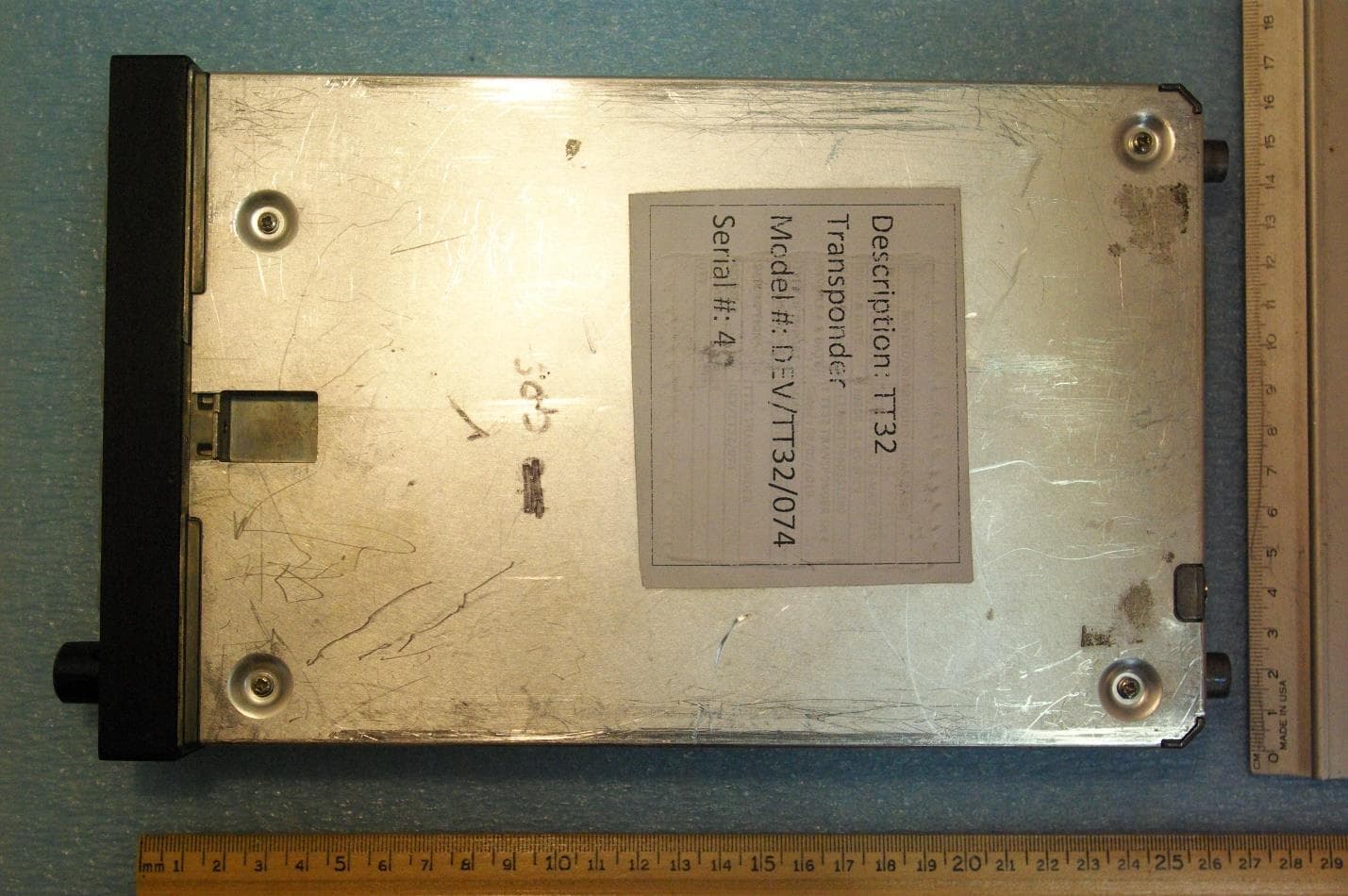
VZI01905
Aug 02, 2021Licensed Non Broadcast Station, Aviation Transponder
Equipment Class
TNB - Licensed Non-Broadcast Station Transmitter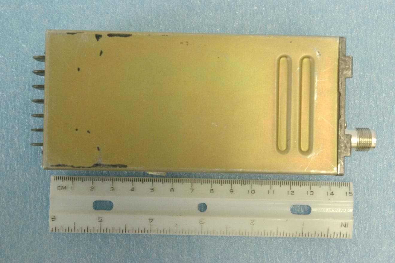
VZI00882
Nov 01, 2012LICENSED NON-BROADCAST AERONAUTICAL TRANSMITTER
Equipment Class
TNB - Licensed Non-Broadcast Station Transmitter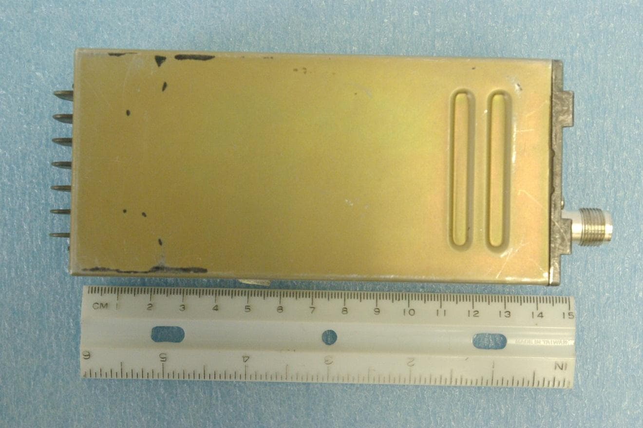
VZI00879
Nov 01, 2012LICENSED NON-BROADCAST AERONAUTICAL TRANSMITTER
Equipment Class
TNB - Licensed Non-Broadcast Station Transmitter