VZS-BARMATE-SRDBARMATE SYSTEM - SRD
BarMate Limited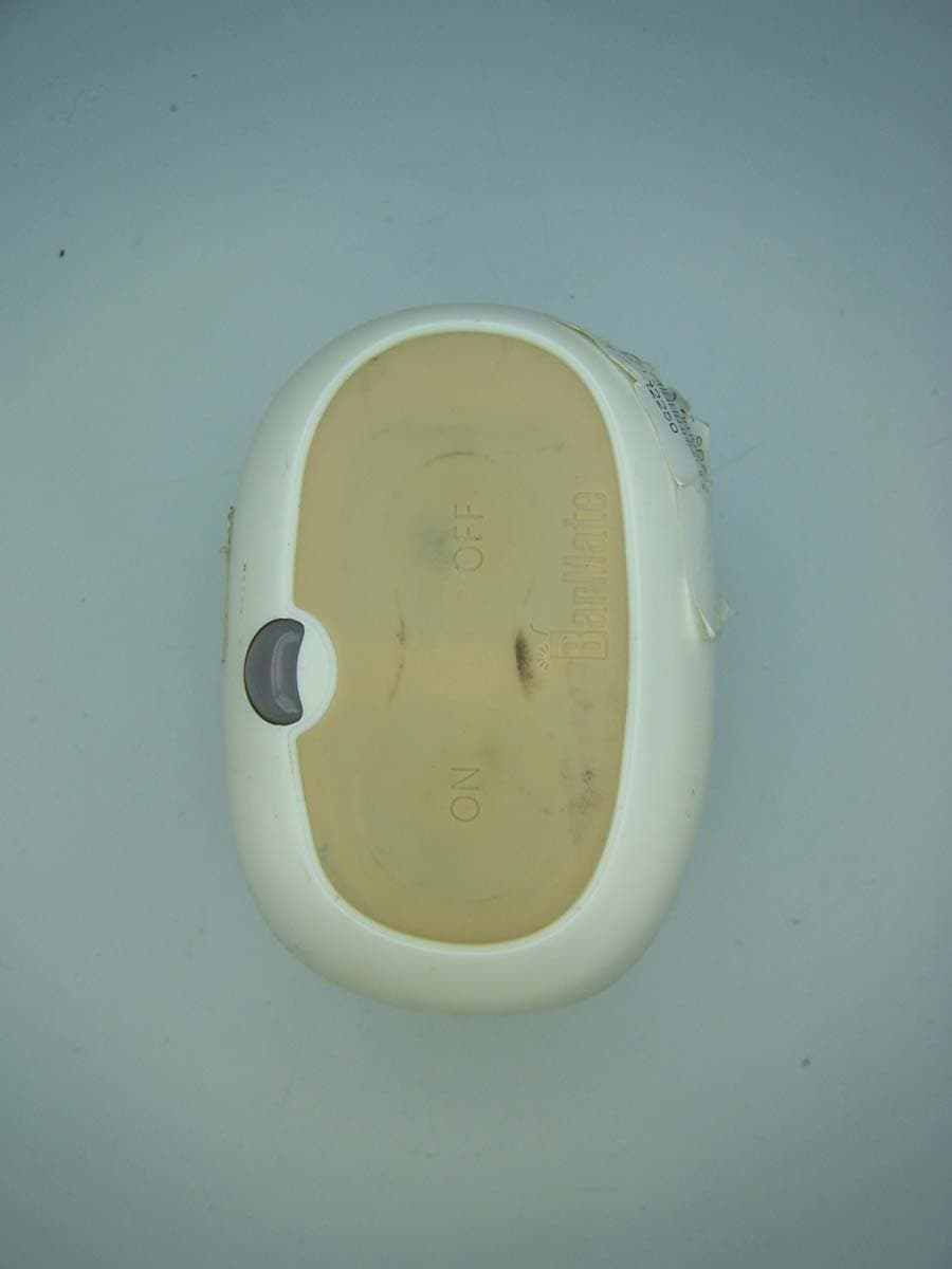
Click to zoom
Application Details
- Equipment Class
- DXX - Part 15 Low Power Communication Device Transmitter
- Date of Grant
- Apr 03, 2008
- Application Purpose
- Original Equipment
- Date of Application
- Apr 03, 2008
- Equipment Note
- BARMATE SYSTEM - SRD
- Frequency Range
- 13.56000000 - 13.56000000
- Company
- BarMate Limited
- Country
- United Kingdom
Documents & Files
Document Text
Text extracted from the exhibit documents filed with the FCC. Open a document above to read the original.
Users Manual
“Poolside Service at the Touch of a Button” Installation Guide Rev A “Poolside Service at the Touch of a Button” Installation Guide Rev. A ii BarMate Installation Guide BarMate Installation Guide iii Notice This guide is provided for informational use only. Every effort was made to ensure accuracy of information in this guide at the time of printing. BarMate reserves the right to provide updates to content information not available at the time this guide was printed. Changes or modifications to the BarMate System not expressly approved by BarMate could void the user’s authority to operate the equipment. Copyright 2008 BarMate Ltd. All rights reserved. BarMate and its logo are trademarks of BarMate. All other trademarks and registered trademarks are the property of their respective owners. No part of this guide may be reproduced manually or electronically without written permission from BarMate. Trademarks BarMate is a trademark or registered trademark of BarMate in the United States, European Union and/or other countries. Federal Communications Commission (FCC) Notice The BarMate system complies with part 15 of the FCC Rules. Operation is subject to the following two conditions: (1) This device may not cause harmful interference, and (2) this device must accept any interference received, including interference that may cause undesired operation. The Service Request Device (SRD) and the Service Area Manager (SAM) have been tested and found to comply with the limits for a Class A digital device, pursuant to part 15 of the FCC Rules. These limits are designed to provide reasonable protection against harmful interference when the equipment is operated in a commercial environment. This equipment generates, uses, and can radiate radio frequency energy and, if not installed and used in accordance with the instruction manual, may cause harmful interference to radio communications. Operation of this equipment in a residential area is likely to cause harmful interference in which case the user will be required to correct the interference at his own expense. The Gateway has been tested and found to comply with the limits for a Class B digital device, pursuant to part 15 of the FCC Rules. These limits are designed to provide reasonable protection against harmful interference in a residential installation. This equipment generates, uses and can radiate radio frequency energy and, if not installed and used in accordance with the instructions, may cause harmful interference to radio communications. However, there is no guarantee that interference will not occur in a iv BarMate Installation Guide particular installation. If this equipment does cause harmful interference to radio or television reception, which can be determined by turning the equipment off and on, the user is encouraged to try to correct the interference by one or more of the following measures: • Reorient or relocate the receiving antenna. • Increase the separation between the equipment and receiver. • Connect the equipment into an outlet on a circuit different from that to which the receiver is connected. • Consult the dealer or an experienced radio/TV technician for help. CE Compliance The BarMate System has been designed and tested to be CE compliant under the R&TTE Directive. BarMate Installation Guide v Important Safety Instructions When installing/using this product, basic safety precautions should always be followed to reduce the risk of fire, electric shock and injury to persons, including the following: 1. Read and understand all instructions. 2. Do not use the Gateway near water. 3. Clean only with dry cloth. 4. Do not locate the antenna near overhead light or power circuits, or where it can fall into such power lines or circuits. When installing the antenna, take extreme care to avoid touching such power lines or circuits, as contact with them can be fatal. 5. Refer all servicing to qualified service personnel. Servicing is required when the equipment has been damaged in any way and does not operate normally. SAVE THESE INSTRUCTIONS vi BarMate Installation Guide Symbols Failure to comply with safety precautions in this guide violates the intended use of this product. The following safety symbols appear in this guide: GENERAL HAZARD This symbol represents a general warning or caution. BarMate Installation Guide vii About This Guide Purpose and scope The purpose of this guide is to introduce the BarMate system and to help you successfully setup and install this product. The scope of this guide describes the BarMate System, components, and capabilities, and provides instruction for installing, setting up, operating, and verifying installation and operation of the system once installed. Audience This guide is intended for trained BarMate Installers. It is assumed that installers have been trained, and have a basic understanding of the BarMate System and installation process when installing a system. Organization The following table is a roadmap to using this guide efficiently. Refer to... To... Chapter 1, The BarMate Overview Understand the BarMate System and how it functions Chapter 2, Installation Install the BarMate system components Chapter 3, Management Centre Setup and Operation Setup and operate the BarMate software. This section also describes how to upload and configure maps, calibrate a SAM, and configure an SRD. Appendix A, BarMate Site Survey See an example survey Appendix B, Specifications Understand cable wiring and pinouts Acronyms See a list of the acronyms used in this guide and the words they represent. Related information Use this guide in conjunction with a completed BarMate site survey. The site survey form is located on page 4 of this guide. Contents viii BarMate Installation Guide Conventions The following table describes typographical and icon conventions used throughout this guide. Description Example A switch you press on a device appears in this TYPEFACE. Press the START switch. Text you must enter exac…
Text truncated - open the document above for the full version.
Users Manual
“Poolside Service at the Touch of a Button” User’s Guide Rev A ii BarMate Installation Guide BarMate Installation Guide iii “Poolside Service at the Touch of a Button” User’s Guide Rev. A iv BarMate Installation Guide BarMate Installation Guide v Notice This guide is provided for informational use only. Every effort was made to ensure accuracy of information in this guide at the time of printing. BarMate reserves the right to provide updates to content information not available at the time this guide was printed. Changes or modifications to the BarMate System not expressly approved by BarMate could void the user’s authority to operate the equipment. Copyright 2008 BarMate Ltd. All rights reserved. BarMate and its logo are trademarks of BarMate. All other trademarks and registered trademarks are the property of their respective owners. No part of this guide may be reproduced manually or electronically without written permission from BarMate. Trademarks BarMate is a trademark or registered trademark of BarMate in the United States, European Union, and/or other countries. Federal Communications Commission (FCC) Notice The BarMate system complies with part 15 of the FCC Rules. Operation is subject to the following two conditions: (1) This device may not cause harmful interference, and (2) this device must accept any interference received, including interference that may cause undesired operation. The Service Request Device (SRD) and the Service Area Manager (SAM) have been tested and found to comply with the limits for a Class A digital device, pursuant to part 15 of the FCC Rules. These limits are designed to provide reasonable protection against harmful interference when the equipment is operated in a commercial environment. This equipment generates, uses, and can radiate radio frequency energy and, if not installed and used in accordance with the instruction manual, may cause harmful interference to radio communications. Operation of this equipment in a residential area is likely to cause harmful interference in which case the user will be required to correct the interference at his own expense. The Gateway has been tested and found to comply with the limits for a Class B digital device, pursuant to part 15 of the FCC Rules. These limits are designed to provide reasonable protection against harmful interference in a residential installation. This equipment generates, uses and can radiate radio frequency energy and, if not installed and used in accordance with the instructions, may cause harmful interference to radio vi BarMate Installation Guide communications. However, there is no guarantee that interference will not occur in a particular installation. If this equipment does cause harmful interference to radio or television reception, which can be determined by turning the equipment off and on, the user is encouraged to try to correct the interference by one or more of the following measures: • Reorient or relocate the receiving antenna. • Increase the separation between the equipment and receiver. • Connect the equipment into an outlet on a circuit different from that to which the receiver is connected. • Consult the dealer or an experienced radio/TV technician for help. CE Compliance The BarMate System has been designed and tested to be CE compliant under the R&TTE Directive. BarMate Installation Guide vii Safety Instructions When installing/using this product, basic safety precautions should always be followed to reduce the risk of fire, electric shock and injury to persons, including the following: 1. Read and understand all instructions. 2. Do not use the Gateway near water. 3. Clean only with dry cloth. 4. Do not locate the antenna near overhead light or power circuits, or where it can fall into such power lines or circuits. When installing the antenna, take extreme care to avoid touching such power lines or circuits, as contact with them can be fatal. Refer all servicing to qualified service personnel. Servicing is required when the equipment has been damaged in any way and does not operate normally. SAVE THESE INSTRUCTIONS viii BarMate Installation Guide Safety Symbols Failure to comply with safety precautions in this guide violates the intended use of this product. The following safety symbols appear in this guide:: GENERAL HAZARD This symbol represents a general warning or caution. BarMate Installation Guide ix About This Guide Purpose and scope The purpose of this guide is to introduce the BarMate system and to help you successfully use this product. The scope of this guide describes the BarMate System, components, and functions, and provides task-based instruction for operating and using this system once installed. Audience This guide is intended for Administrators and Waiters. It is assumed that users have a basic understanding of a PC computer or laptop. Organization The following table is a roadmap to using this guide efficiently. Refer to... To... Chapter 1, The BarMate Overview Understand the BarMate System and the function of system components. Chapter 2, Operations Understand component operation and how to start and operate the Management Centre software. Chapter 3, Starting and Using the Management Centre Understand Management Centre Operations and how to manage personnel and service requests. Chapter 4, Maintenance Learn how to replace an SRD when it no longer operates (battery runs out). x BarMate Installation Guide Conventions The following table describes typographical and icon conventions used throughout this guide. Description Example A button or switch you press on a device appears in this TYPEFACE. On the SRD, press the ON button. A greater than symbol (>) indicates choosing a submenu from a menu. On the status bar, choose Start > BARMATE Management Centre. An arrow represents a tip or conveys related information. ► Acronyms FCC – Federal Communications Commission LED – Light Emitted Device MC – Management Centre MMC – Master Management Centre PC – Personal Co…
Text truncated - open the document above for the full version.
Cover Letter(s)
BarMate Limited BarMate Ltd. Northway House 1379 High Road London N20 9LP 020 8445 1355 31 st January 2008 MET Laboratories, Inc. 914 West Patapsco Avenue Baltimore, MD 21230 RE: LETTER OF AGENT AUTHORIZATION To Whom It May Concern: We, the undersigned, hereby authorize MET Laboratories Inc. to act on our behalf in all matters relating to application for equipment authorization, including the signing of all documents relating to these matters. We also hereby certify that no party to the application authorized hereunder is subject to the denial of benefits, including FCC benefits, pursuant to Section 5301 of the Anti-Drug Abuse Act of 1988, 21 U.S.C.853(a). This agreement expires one year from the current date. Sincerely, Phil Tyler Chief Operating Officer BarMate Ltd
Cover Letter(s)
BarMate Limited BarMate Ltd. Northway House 1379 High Road London N20 9LP 020 8445 1355 31 st January 2008 MET Laboratories, Inc. 914 West Patapsco Avenue Baltimore, MD 21230 RE: CONFIDENTIALITY REQUEST FOR: Grantee Code Registration Number: GC457775 FCC ID: VZS-BARMATE-SRD EUT NAMES/MODELS: BarMate System: Service Request Device (SRD) To Whom It May Concern: This letter serves as an official request for confidentiality under sections 0.457 and 0.459 of CFR 47. We have requested that all documentation submitted with this application be permanently withheld from public review. This includes but is not limited to: - Circuit schematics - Parts lists - Block Diagrams The specified documents are part of BarMate Limited proprietary information and intellectual property. Likewise, the specifics of tests undertaken and their results give substantial clues as to the internal workings of the BarMate product. As such, this information should not be made available to potential competitors. Please contact me if there is any information you may need. Sincerely, Phil Tyler Chief Operating Officer BarMate Ltd
External Photos
Photograph 1. BarMate System, SRD, Back View Photograph 2. BarMate System, SRD, Front View
Internal Photos
Photograph 1. BarMate System, SRD Photograph 2. BarMate System, SRD Photograph 3. BarMate System, SRD Photograph 4. BarMate System, SRD Photograph 5. BarMate System, SRD Photograph 6. BarMate System, SRD
Operational Description
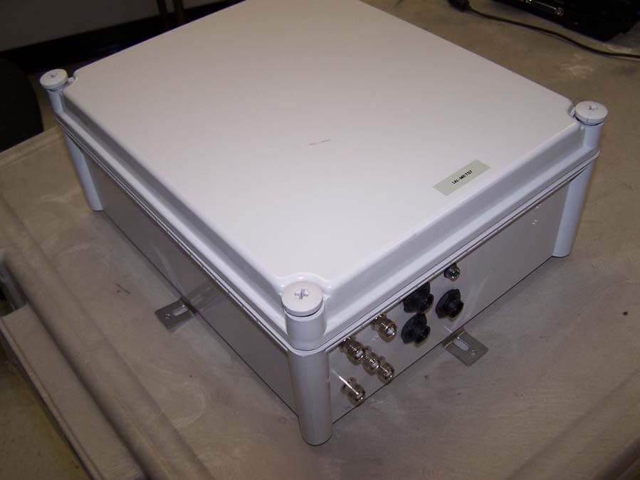
About BarMate BarMate is a wireless system that allows guests to request bar service with the press of a button. The wireless device sends a request for service signal to a nearby bar. Service is then provided by a waiter/waitress. After providing prompt service, the waiter/waitress clears the signal indicating the guest has been served. The BarMate system is designed to be scalable, flexible, and accurate for any resort environment. How BarMate works To request service, a guest presses a button on a Service Request Device (SRD), which sends a signal to the Management Centre (MC) or the Master Management Centre (MMC), usually located at the bar or refreshment area to request service. The Management Centre consists of a Gateway and a touchscreen personal computer (PC) running BarMate software. A Waiter will identify the location of the guest using the BarMate software, and promptly respond to the guest requesting service. An LED will illuminate on the SRD to help identify the guest requesting service. After responding to a guests request for service, the Waiter clears the signal on the SRD to indicate the guest has received the requested service. Clearing the signal will switch the LED on the SRD off and send relevant service data (date and time service request was fulfilled) to the Management Centre. Wireless communications between the SRD and the Gateway are managed by the Service Area Manager (SAM), inconspicuous devices located between the SRDs and the MC to manage wireless communication traffic between devices and assist with identifying the guests’ location. System description The following diagram illustrates the BarMate System. A description of system components follows. Figure 1: System Block Diagram. Technical description of system components The BarMate system sends and receives data using multiple devices. Each device is described below. Service Request Device (SRD) – A push button device that Transmits (TX) and Receives (RX) a signal to and from the Service Area Manager (SAM). An LED (Light Emitted Device) illuminates on the SRD, indicating service request. The illuminated LED identifies the guest requesting service and also lets the guest know the SRD is active. This is a battery powered, wireless device that attaches to a surface, typically on a sun lounger. Service Area Manager (SAM) – A device that manages service requests from SRDs. The SAM transmits and receives signals to and from SRDs using the Antenna Array. The SAM also uses a COM antenna to transmit and receive signals between the SAM and the Gateway. The SAM is powered with a battery that can be recharged using a solar panel and cable. For environmental protection against outdoor elements, the SAM shell (box casing) is a NEMA 4 rated enclosure. Antenna Array – Composed of four antennas that connect to a SAM. The array transmits and receives signals between SRDs and a SAM. The array locates the SRD requesting service by triangulation. COM Antennas – Connect to the SAM and to the Gateway (one antenna for each device) by coaxial cable. The COM antennas transmit and receive signals between the Gateway and the SAM. Solar Panel – Connects to the SAM to recharge the battery. Gateway – Communicates wirelessly with one or more SAMs using a COM antenna. The Gateway is part of the Management Centre (MC) and connects to the MC computer using a USB cable. The COM antenna attaches to the Gateway with a coaxial cable. Management Centre (MC) – Composed of a Gateway and a touchscreen computer running the BarMate software. The MC is usually located in the bar area, and provides the interface between the BarMate system and the site’s wait staff. A site may have multiple MCs. The MC computer connects to the Gateway with a USB cable. Master Management Center (MMC) – Like the MC, the MMC is composed of a Gateway and a touchscreen computer running the BarMate software. At sites that have multiple MCs, the MMC routes messages between MCs as required. The MMC can also function as an interface between the BarMate System and the site’s wait staff. BarMate software The BarMate software runs on the MC or MMC computer. The BarMate software enables waiters to identify the location of guests requesting service and to indicate when the guest has been served. The BarMate software enables Administrators to manage and assign waiters at specific MC locations.
RF Exposure Info
Part # 1616, Revision A Company Confidential Page 1 of 12 SRD RFID Antenna Assembly Drawing 5/31/2007 Part #: 1616 Revision: Rev A © 2007 IAI Notice: All rights reserved. All information contained in this document is confidential and proprietary to IAI and its affiliates, and intended only for the addressee to whom this copy is addressed. The recipient shall neither copy, distribute, disclose or use the information contained in this document for any purpose other than for which it has been made available, nor permit anyone else to do the same. The recipient shall be held fully liable for any wrongful disclosure or use of any of the information contained in this document by him, or his officers or employees or anyone else to whom he makes the information available. Revision History: Revision Changes Revised By Date 1.0 Initial Release Gabe Mayo 1/30/07 1.1 Changed ferrite core length, included offset dimension Mark W. Stevenson 5/29/07 A Released Ben Bachrach 5/31/07 Part Description: The following part is the antenna for the SRD component of the BarMate project. General: The assembly shall meet the requirements of the European Union ROHS directives, and shall be capable of withstanding ROHS-compliant assembly temperatures. Marking: Packaging container shall be marked with part number and revision of this drawing, and a statement that this product is ROHS compliant. Part # 1616, Revision A Company Confidential Page 2 of 12 Electrical Characteristics: Operating Frequency ...................................................................... 13.560MHz Primary Inductance, (secondary open) .......................................... 64.2nH ±4% Secondary Resonant Frequency (25.70pF parallel cap) ................. 13.560MHz ±2% at 25C Q-Factor (secondary resonant at 13.560MHz) .............................. >110 Operating Temperature .................................................................. 0C to 60C Materials: [1] Ferrite Core, 0.50”x1.772” (45.0 mm), #61 material, Fair-Rite # [2] Magnet Wire, 24 AWG, Solderable, Double Coated [3] Barrier Tape, Polyester film, 1” wide [4] Barrier Tape, Polyester film, 0.5” wide [5] Barrier Tape, Polyester film, 0.25” wide [6] Copper Strap, shim stock, 0.003”, 0.75 wide, 2.188” long Part # 1616, Revision A Company Confidential Page 3 of 12 NOTE: Photographs in right column are for illustrative purposes only. The SRD antenna is constructed with a ferrite core, magnet wire, Copper shim stock, and transformer tape. The Antenna is surface mounted on the side of a PCB as shown Step 1a: Secure start of secondary winding lengthwise with tape of material [4]. The wire is located 0.20” from the end of the ferrite rod. Ferrite Core Secondary Winding (Magnet Wire) Primary Winding (Copper Strap) PC Board Secondary Connections Primary Connections 0.5” x 1.0” 0.20” Part # 1616, Revision A Company Confidential Page 4 of 12 Step 1b: Secure the start of the winding by wrapping 2x transformer tape, material [5] (0.25”) at both sides of the wire. Step 2: Wind 10 turns of magnet wire, material [2]. The winding should be evenly spread, centered and span 1.375” (back) (Front) Back Lead Front Lead 1.375” 0.20” 0.20” Part # 1616, Revision A Company Confidential Page 5 of 12 Step3a: Secure the end of the winding by taping it down lengthwise with transformer tape of material [4]. Step3b: Secure the end of the winding by wrapping 2x transformer tape, material [5] (0.25”) just beyond the end of the winding. Part # 1616, Revision A Company Confidential Page 6 of 12 Step3c: Wrap 2x material [4] (0.50”) just inside the end of the winding. Step3d: Wrap 2x material [3] (1.00”) just inside the opposing end of the winding. Note: Leads should exit through the gap between the wrappings. Part # 1616, Revision A Company Confidential Page 7 of 12 Step 4: Wrap 0.75” copper strap, Material [6] Step 5: Secure Strap lengthwise with 1.0” transformer tape, Material [3] as shown. Wrap Copper Strap Centered on Ferrite 0.75” x 2.188” 0.75” Part # 1616, Revision A Company Confidential Page 8 of 12 Step 6a: Form leads on Magnet wire and copper strap to mate 0.062” thick spacer, offset by 0.132” below center. Dimensions for offset are shown end of document. Note: Leads are formed on front and back of spacer. Step 6b: Secure ends of formed leads by taping them down lengthwise with transformer tape of material [4]. 1.75” 0.5” tape, Front and Back Part # 1616, Revision A Company Confidential Page 9 of 12 Step 6c: Secure the ends by wrapping 2x transformer tape, material [5] (0.25”) just at both sides of each lead (4 wrappings). Step 7a: Trim Leads Note: Trimming may take place at an earlier or later step. 0.25” 0.25” 0.25” 0.25” Trim & Tin Form Leads 0.062” Part # 1616, Revision A Company Confidential Page 10 of 12 Step 7b: Tin the leads and dip in Varnish Note: Tinning and Varnish may take place at an earlier or later step. Step 7c: Insert 0.062” spacer to protect formed leads. Varnish Dip Form Leads 0.062” 1.375”, Centered (Insert Lead Protector) 0.75”, Centered Part # 1616, Revision A Company Confidential Page 11 of 12 PCB Mounting Example SRD antenna Copper Strap detail: Copper strap needs to be formed according to the following drawing to comply with plastics design. Revised 05/07/07 Solder Secondary, Front Solder Secondary, Rear Solder Primary, Front and Rear PCB Part # 1616, Revision A Company Confidential Page 12 of 12 Antenna Circuit Example Operating Frequency ...................................................................... 13.560MHz Typical Thermal Stability (0C to 60C) ......................................... ±15kHz Typical Q-Factor ............................................................................ 110 to 130 at 25C Input Impedance ............................................................................ 50 Ohm Max Input Power ........................................................................... +30dBm C1,C2,C3 values (pF) ...............................................…
Text truncated - open the document above for the full version.
Test Report
MET Laboratories, Inc. Safety Certification - EMI - Telecom Environmental Simulation 914 WEST PATAPSCO AVENUE ! BALTIMORE, MARYLAND 21230-3432 ! PHONE (410) 354-3300 ! FAX (410) 354-3313 The Nation’s First Licensed Nationally Recognized Testing Laboratory February 18, 2008 BarMate LTD 1379 High Road London, United Kingdom N20 9LP Dear Peter Teichman, Enclosed is the EMC test report for compliance testing of the BarMate LTD, The BarMate System-SRD, tested to the requirements of Title 47 of the CFR, Part 15.225, Subpart C for Certification as an Intentional Radiator. Thank you for using the services of MET Laboratories, Inc. If you have any questions regarding these results or if MET can be of further service to you, please feel free to contact me. Sincerely yours, MET LABORATORIES, INC. Angela D. Brown Documentation Department Reference: (\BarMate LTD\ EMC22250-FCC225 Rev. 1) Certificates and reports shall not be reproduced except in full, without the written permission of MET Laboratories, Inc. While use of the National Voluntary Laboratory Accreditation Program (NVLAP) letters or the NVLAP Logo, the Standards Council of Canada Logo, A2LA, or the Nationally Recognized Testing Laboratory (NRTL) Letters in this report reflects MET Accreditation under these programs, these letters, logo, or statements do not claim product endorsement by these organizations or any Agency of the U.S. Government. This letter of transmittal is not a part of the attached report. DOC-EMC705 2/26/2004 MET Laboratories, Inc. Safety Certification - EMI - Telecom Environmental Simulation 914 WEST PATAPSCO AVENUE ! BALTIMORE, MARYLAND 21230-3432 ! PHONE (410) 354-3300 ! FAX (410) 354-3313 DOC-EMC705 2/26/2004 Electromagnetic Compatibility Criteria Test Report For the BarMate LTD The BarMate System-SRD Tested under The FCC Certification Rules Contained in Title 47 of the CFR, Part 15, Subpart C For Certification as a Intentional Radiator MET Report: EMC22250-FCC225 Rev. 1 February 18, 2008 Prepared For: BarMate LTD 1379 High Road London, United Kingdom N20 9LP Prepared By: MET Laboratories, Inc. 914 West Patapsco Avenue Baltimore, MD 21230 BarMate LTD Electromagnetic Compatibility The BarMate System - SRD CFR Title 47, Part 15, Subpart C MET Report: EMC22250-FCC225 Rev. 1 © 2008, MET Laboratories, Inc. Page ii of vi DOC-EMC705 2/26/2004 Electromagnetic Compatibility Criteria Test Report For the BarMate LTD The BarMate System-SRD Tested under The FCC Certification Rules Contained in Title 47 of the CFR, Part 15, Subpart C For Certification as a Intentional Radiator MET Report: EMC22250-FCC225 Rev. 1 Dusmantha Tennakoon Angela D. Brown Project Engineer, Electromagnetic Compatibility Lab Documentation Department Engineering Statement: The measurements shown in this report were made in accordance with the procedures indicated, and the emissions from this equipment were found to be within the limits applicable. I assume full responsibility for the accuracy and completeness of these measurements, and for the qualifications of all persons taking them. It is further stated that upon the basis of the measurements made, the equipment tested is capable of operation in accordance with the requirements of Title 47 of the CFR, Part 15, Subpart C for Certification as a Intentional Radiator and Part 15, Subpart B for a Class B Unintentional Radiator under normal use and maintenance. Shawn McMillen, Wireless Coordinator, Electromagnetic Compatibility Lab BarMate LTD Electromagnetic Compatibility The BarMate System - SRD CFR Title 47, Part 15, Subpart C MET Report: EMC22250-FCC225 Rev. 1 © 2008, MET Laboratories, Inc. Page iii of vi DOC-EMC705 2/26/2004 Report Status Sheet Revision Report Date Reason for Revision ∅ February 15, 2008 Initial Issue. 1 February 18, 2008 Correction of Primary Power on pg. 2. BarMate LTD Electromagnetic Compatibility The BarMate System - SRD CFR Title 47, Part 15, Subpart C MET Report: EMC22250-FCC225 Rev. 1 © 2008, MET Laboratories, Inc. Page iv of vi DOC-EMC705 2/26/2004 Table of Contents 1. Testing Summary ............................................................................................................................................................1 2. Equipment Configuration...............................................................................................................................................2 2.1.1.1. Overview............................................................................................................................................ 2 2.1.1.2. References.......................................................................................................................................... 3 2.1.1.3. Test Site ............................................................................................................................................. 3 2.1.1.4. Description of Test Sample................................................................................................................ 3 2.1.1.5. Equipment Configuration................................................................................................................... 4 2.1.1.6. Mode of Operation............................................................................................................................. 5 2.1.1.7. Modifications ..........................................................................................…
Text truncated - open the document above for the full version.
Contact Information
Applicant
Philip Tyler(COO)
Technical Contact
BarMate LimitedPhilip Tyler
[email protected]+44 208 445 1355
Northway House · London · United Kingdom
Test Firm
EUROFINS ELECTRICAL AND ELECTRONIC TESTING NA, INCGreg Kovolenko
Technical Specifications
| # | Rule Parts | Frequency Range | Power Output |
|---|---|---|---|
| 1 | 15C | 13.56 MHz - 13.56 MHz | - |
Other Applications from BarMate Limited
VZS-BARMATE-SAM
Apr 03, 2008BARMATE SYSTEM - SAM
Equipment Class
DTS - Digital Transmission System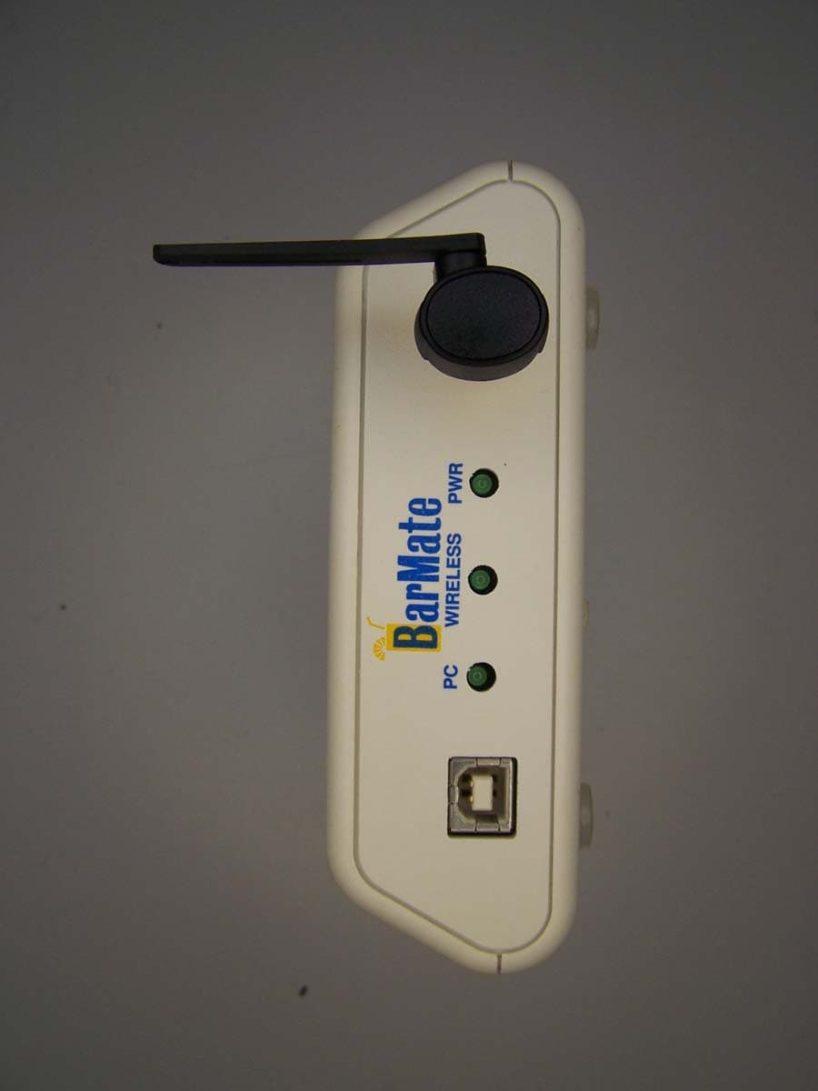
VZS-BARMATE
Apr 02, 2008BARMATE SYSTEM - Gateway
Equipment Class
DTS - Digital Transmission System