W5HSBG6580DOCSIS 3.0 Wi-Fi Gateway
ARRIS Taiwan, Ltd.
Click to zoom
Application Details
- Equipment Class
- NII - Unlicensed National Information Infrastructure TX
- Date of Grant
- Jan 17, 2010
- Application Purpose
- Original Equipment
- Date of Application
- Jan 17, 2010
- Equipment Note
- DOCSIS 3.0 Wi-Fi Gateway
- Frequency Range
- 5180.00000000 - 5240.00000000
- Company
- ARRIS Taiwan, Ltd.
- Country
- Taiwan
Documents & Files
Document Text
Text extracted from the exhibit documents filed with the FCC. Open a document above to read the original.
Users Manual
M User Guide Motorola SURFboard ® SBG6580 Series Wi-Fi Cable Modem Gateway* © 2009 Motorola, Inc. All rights reserved. No part of this publication may be reproduced in any form or by any means or used to make any derivative work (such as translation, transformation, or adaptation) without written permission from Motorola, Inc. Motorola reserves the right to revise this publication and to make changes in content from time to time without obligation on the part of Motorola to provide notification of such revision or change. Motorola provides this guide without warranty of any kind, implied or expressed, including, but not limited to, the implied warranties of merchantability and fitness for a particular purpose. Motorola may make improvements or changes in the product(s) described in this manual at any time. Motorola and the Stylized M logo are registered trademarks of Motorola, Inc. All other product or service names are the property of their respective owners. i Safety and Regulatory Information IMPORTANT SAFETY INSTRUCTIONS Read This Before You Begin When using your equipment, basic safety precautions should always be followed to reduce the risk of fire, electric shock, and injury to persons, including the following: • Read all of the instructions listed here and/or in the user manual before you operate this device. Give particular attention to all safety precautions. Retain the instructions for future reference. • This device must be installed and used in strict accordance with manufacturer’s instructions, as described in the user documentation that is included with the device. • Comply with all warning and caution statements in the instructions. Observe all warning and caution symbols that are affixed to this device. • To prevent fire or shock hazard, do not expose this device to rain or moisture. The device must not be exposed to dripping or splashing. Do not place objects filled with liquids, such as vases, on the device. • This device was qualified under test conditions that included the use of the supplied cables between system components. To ensure regulatory and safety compliance, use only the provided power and interface cables and install them properly. • Different types of cord sets may be used for connections to the main power supply circuit. Use only a main line cord that complies with all applicable device safety requirements of the country of use. • Installation of this device must be in accordance with national wiring codes and conform to local regulations. • Operate this device only from the type of power source indicated on the device’s marking label. If you are not sure of the type of power supplied to your home, consult your dealer or local power company. • Do not overload outlets or extension cords, as this can result in a risk of fire or electric shock. Overloaded AC outlets, extension cords, frayed power cords, damaged or cracked wire insulation, and broken plugs are dangerous. They may result in a shock or fire hazard. • Route power supply cords so that they are not likely to be walked on or pinched by items placed upon or against them. Pay particular attention to cords where they are attached to plugs and convenience receptacles, and examine the point where they exit from the device. • Place this device in a location that is close enough to an electrical outlet to accommodate the length of the power cord. • Place the device to allow for easy access when disconnecting the power cord of the device from the AC wall outlet. • Do not connect the plug into an extension cord, receptacle, or other outlet unless the plug can be fully inserted with no part of the blades exposed. • Place this device on a stable surface. • Avoid damaging the cable modem with static by touching the coaxial cable when it is attached to the earth-grounded coaxial cable-TV wall outlet. • Always first touch the coaxial cable connector on the cable modem when disconnecting or reconnecting the Ethernet cable from the cable modem or user’s PC. • It is recommended that the customer install an AC surge protector in the AC outlet to which this device is connected. This is to avoid damaging the device by local lightning strikes and other electrical surges. • Postpone installation until there is no risk of thunderstorm or lightning activity in the area. • Do not cover the device or block the airflow to the device with any other objects. Keep the device away from excessive heat and humidity and keep the device free from vibration and dust. • Wipe the device with a clean, dry cloth. Never use cleaning fluid or similar chemicals. Do not spray cleaners directly on the device or use forced air to remove dust. • Upon completion of any service or repairs to this device, ask the service technician to perform safety checks to determine that the device is in safe operating condition. • Do not open the device. Do not perform any servicing other than that contained in the installation and troubleshooting instructions. Refer all servicing to qualified service personnel. • This device should not be used in an environment that exceeds 40º C. SAVE THESE INSTRUCTIONS Note to CATV System Installer: This reminder is provided to call the CATV system installer’s attention to Section 820.93 of the National Electric Code, which provides guidelines for proper grounding and, in particular, specifies that the coaxial cable shield shall be connected to the grounding system of the building, as close to the point of cable entry as practical. Caring for the Environment by Recycling When you see this symbol on a Motorola product, do not dispose of the product with residential or commercial waste. Recycling your Motorola Equipment Please do not dispose of this product with your residential or commercial waste. Some countries or regions, such as the European Union, have set up systems to collect and recycle electrical and electronic waste items. Contact your local authorities for information about practices established for your region.…
Text truncated - open the document above for the full version.
External Photos
Page 1 CONSTRUCTION PHOTOS OF EUT Model: SBG6580 Page 2 Page 3 Page 4 Model: SBG6580 Diagnostic Page 5
ID Label/Location Info
FCC ID .: W5HSBG6580 Model: SBG6580 Label Location Model: SBG6580 Diagnostic Label Location
ID Label/Location Info
Input Voltage: +12VDC - - - ; 1 5A. Model: SBG6580 DIAGNOSTIC DOCSIS 3.0 I.T.E. E315754 FOR HOME OR OFFICE USE Tested To Comply With FCC Standards Model: SBG6580 DIAGNOSTIC SURFboard FCC ID: W5HSBG6580 IC: 5117A SBG6580- ARTWORK, LABEL, ID, REGULATORY, SBG6580 DIAGNOSTIC 2 SHEET 1 OF 1 SCALE: 1:1 DRAWING NO: REV PROJECT SIZE A TITLE SURFBOARD FILE: 572455-007-2.cdr 572455-007 San Diego, CA, USA NOTES: UNLESS OTHERWISE SPECIFIED 1. DIMENSIONS ARE METRIC (MILLIMETERS). INTERPRET PER ANSI Y14.5M. 2. TEXT FONTS USED IN THIS FILE: ARIAL GIOFFICINASANS AVANGARDE BK BT 3. COLOR: BACKGROUND = PMS 811C FOREGROUND = BLACK ARIAL Unicode MS ARIAL Black ARIAL Narrow Swiss721 Blk BT REVISION STATUS 111/11/09J.DORSETTENGINEERING RELEASE PER ECN C379067 201/05/10J.DORSETTREVISED PER ECN C387186. REVDATEDESIGNDESCRIPTION 34.00 mm 51.00 mm
Internal Photos
Page 6 Model: SBG6580 Page 7 Page 8 Model: SBG6580 Diagnostic Page 9 Page 10 Model: SBG6580 Model: SBG6580 Diagnostic Page 11 Page 12 Page 13 Page 14 Page 15 Page 16 Page 17 Page 18
Operational Description
FCC ID: W5HSBG6580 Report No.: RF981212L01 OPERATIONAL DESCRIPTION This device is a DOCSIS 3.0 Wi-Fi Gateway, which operates in the 2.4GHz frequency spectrum with throughput of up to 300Mbps which OFDM technique will be applied. If the signal to noise ratio is too poor which could not support 300Mbps, the 11Mbps data rate with DSSS technique will be applied. The transmitter of the EUT is powered by AC adapter. The antenna is Printed antenna with UFL antenna connector. FCC 15.407(c) states: The device shall automatically discontinue transmission in case of either absence of information to transmit or operational failure. These provisions are not intended to preclude the transmission of control or signaling information or the use of repetitive codes used by certain digital technologies to complete frame or burst intervals. Applicants shall include in their application for equipment authorization a description of how this requirement is met” Data transmission is always initiated by software, which is then pass down through the MAC, through the digital and analog baseband, and finally to the RF chip. Several special packets (ACKs, CTS, PSPoll, etc...) are initiated by the MAC. There are the only ways the digital baseband portion will turn on the RF transmitter, which it then turns off at the end of the packet. Therefore, the transmitter will be on only while one of the aforementioned packets are being transmitted. The other instruction, please have a look at the users manual.
RF Exposure Info
FCC ID: W5HSBG6580 Report No.: SA981212L01 Report Format Version 3.0.1 1 RF EXPOSURE REPORT REPORT NO.: RF981212L01 MODEL NO.: SBG6580 Diagnostic, SBG6580 ACCORDING: FCC Guidelines for Human Exposure IEEE C95.1 APPLICANT: GENERAL INSTRUMENT OF TAIWAN, LTD. ADDRESS: 1, Lane 232 , Pao Chiao Road , Shin Dian, Taipei, Taiwan 231 , R.O.C. ISSUED BY: Bureau Veritas Consumer Products Services (H.K.) Ltd., Taoyuan Branch LAB ADDRESS: No. 47, 14th Ling, Chia Pau Tsuen, Lin Kou Hsiang, Taipei Hsien 244, Taiwan, R.O.C. TEST LOCATION: No. 19, Hwa Ya 2nd Rd, Wen Hwa Tsuen, Kwei Shan Hsiang, Taoyuan Hsien 333, Taiwan, R.O.C. FCC ID: W5HSBG6580 Report No.: SA981212L01 Report Format Version 3.0.1 2 RF EXPOSURE MEASUREMENT (MOBILE DEVICE) 1. INTRODUCTION In this document, we try to prove the safety of radiation harmfulness to the human body for our product. The limit for Maximum Permissible Exposure (MPE) specified in FCC 1.1310 is followed. The Gain of the antenna used in this product is measured in a Fully Anechoic Chamber (FAC) calibrated for antenna measurement in ADT, and also the maximum total power input to the antenna is measured. Through the Friis transmission formula and the maximum gain of the antenna, we can calculate the distance, away from the product, where the limit of MPE is reached. Although the Friis transmission formula is a far field assumption, the calculated result of that is an over-prediction for near field power density. We will take that as the worst case to specify the safety range. 2. RF EXPOSURE LIMIT According to FCC 1.1310: The criteria listed in the following table shall be used to evaluate the environmental impact of human exposure to radio-frequency (RF) radiation as specified in 1.1307(b) LIMITS FOR MAXIMUM PERMISSIBLE EXPOSURE (MPE) FREQUENCY RANGE (MHz) ELECTRIC FIELD STRENGTH (V/m) MAGNETIC FIELD STRENGTH (A/m) POWER DENSITY (mW/cm 2 ) AVERAGE TIME (minutes) (A)LIMITS FOR OCCUPATIONAL / CONTROL EXPOSURES 300-1500 ... ... F/300 6 1500-100,000 ... ... 5 6 (B)LIMITS FOR GENERAL POPULATION / UNCONTROLLED EXPOSURE 300-1500 ... ... F/1500 30 1500-100,000 ... ... 1.0 30 F = Frequency in MHz FCC ID: W5HSBG6580 Report No.: SA981212L01 Report Format Version 3.0.1 3 3. FRIIS FORMULA Friis transmission formula : Pd = (Pout*G) / (4*pi*r 2 ) where Pd = power density in mW/cm 2 Pout = output power to antenna in mW G = gain of antenna in linear scale Pi = 3.1416 R = distance between observation point and center of the radiator in cm If we know the maximum Gain of the antenna and the total power input to the antenna, through the calculation, we will know the MPE value at distance r. Ref.: David K. Cheng, Field and Wave Electromagnetics, Second Edition, Page 640, Eq. (11-133). 4. EUT OPERATING CONDITION The software provided by Manufacturer enabled the EUT to transmit and receive data at lowest, middle and highest channel individually. 5. CLASSIFICATION The antenna of this product, under normal use condition, is at least 20cm away from the body of the user. Warning statement to the user for keeping at least 20cm or more separation distance with the antenna should be included in users manual. So, this device is classified as Mobile Device. FCC ID: W5HSBG6580 Report No.: SA981212L01 Report Format Version 3.0.1 4 6. TEST RESULTS 6.1 ANTENNA GAIN The maximum Gain measured in Fully Anechoic Chamber are 5.2dBi or 3.31(numeric) (for 2.4GHz); 5.5dBi or 3.55(numeric) (for 5.0GHz). 6.2 OUTPUT POWER INTO ANTENNA & RF EXPOSURE VALUE AT DISTANCE 20cm: For 2.412 ~ 2.462GHz band: POWER OUTPUT (dBm) CHAIN 0 CHAIN 1 TOTAL POWER (mW) TOTAL POWER (dBm) POWER DENSITY (mW/ cm 2 ) LIMIT OF POWER DENSITY (mW/ cm 2 ) 20.8 21.1 249.1 24.0 0.165 1.000 For 5.180 ~ 5.240GHz band: POWER OUTPUT (dBm) CHAIN 0 CHAIN 1 TOTAL POWER (mW) TOTAL POWER (dBm) POWER DENSITY (mW/ cm 2 ) LIMIT OF POWER DENSITY (mW/ cm 2 ) 13.4 13.2 42.8 16.3 0.030 1.000 For 5.745 ~ 5.825GHz band: POWER OUTPUT (dBm) CHAIN 0 CHAIN 1 TOTAL POWER (mW) TOTAL POWER (dBm) POWER DENSITY (mW/ cm 2 ) LIMIT OF POWER DENSITY (mW/ cm 2 ) 22.3 23.2 378.8 25.8 0.268 1.000
Test Report
Report No.: RF981212L01 1 Report Format Version 3.0.1 FCC TEST REPORT (15.247) REPORT NO.: RF981212L01 MODEL NO.: SBG6580 Diagnostic (refer to item 3.1 for more detail) RECEIVED: Dec. 14, 2009 TESTED: Dec. 23 ~ Dec. 29, 2009 ISSUED: Jan. 04, 2010 APPLICANT: GENERAL INSTRUMENT OF TAIWAN, LTD. ADDRESS: 1, Lane 232 , Pao Chiao Road , Shin Dian, Taipei, Taiwan 231 , R.O.C. ISSUED BY: Bureau Veritas Consumer Products Services (H.K.) Ltd., Taoyuan Branch LAB ADDRESS: No. 47, 14th Ling, Chia Pau Tsuen, Lin Kou Hsiang, Taipei Hsien 244, Taiwan, R.O.C. TEST LOCATION: No. 19, Hwa Ya 2nd Rd, Wen Hwa Tsuen, Kwei Shan Hsiang, Taoyuan Hsien 333, Taiwan, R.O.C. This test report consists of 132 pages in total. It may be duplicated completely for legal use with the approval of the applicant. It should not be reproduced except in full, without the written approval of our laboratory. The client should not use it to claim product endorsement by TAF or any government agencies. The test results in the report only apply to the tested sample. Report No.: RF981212L01 2 Report Format Version 3.0.1 TABLE OF CONTENTS 1. CERTIFICATION........................................................................................................... 5 2. SUMMARY OF TEST RESULTS .................................................................................. 6 2.1 MEASUREMENT UNCERTAINTY................................................................................ 6 3. GENERAL INFORMATION ........................................................................................... 7 3.1 GENERAL DESCRIPTION OF EUT ............................................................................. 7 3.2 DESCRIPTION OF TEST MODES ............................................................................... 9 3.2.1 CONFIGURATION OF SYSTEM UNDER TEST .......................................................... 9 3.2.2 TEST MODE APPLICABILITY AND TESTED CHANNEL DETAIL ............................. 10 3.3 GENERAL DESCRIPTION OF APPLIED STANDARDS ............................................ 14 3.4 DESCRIPTION OF SUPPORT UNITS ....................................................................... 14 4. TEST TYPES AND RESULTS (FOR 2.4GHz BAND) ................................................. 15 4.1 RADIATED EMISSION MEASUREMENT .................................................................. 15 4.1.1 LIMITS OF RADIATED EMISSION MEASUREMENT................................................ 15 4.1.2 TEST INSTRUMENTS................................................................................................ 16 4.1.3 TEST PROCEDURES ................................................................................................ 17 4.1.4 DEVIATION FROM TEST STANDARD....................................................................... 17 4.1.5 TEST SETUP.............................................................................................................. 18 4.1.6 EUT OPERATING CONDITIONS ............................................................................... 18 4.1.7 TEST RESULTS ......................................................................................................... 19 4.2 CONDUCTED EMISSION MEASUREMENT ............................................................. 35 4.2.1 LIMITS OF CONDUCTED EMISSION MEASUREMENT........................................... 35 4.2.2 TEST INSTRUMENTS................................................................................................ 35 4.2.3 TEST PROCEDURES ................................................................................................ 36 4.2.4 DEVIATION FROM TEST STANDARD....................................................................... 36 4.2.5 TEST SETUP.............................................................................................................. 37 4.2.6 EUT OPERATING CONDITIONS ............................................................................... 37 4.2.7 TEST RESULTS ......................................................................................................... 38 4.3 6dB BANDWIDTH MEASUREMENT.......................................................................... 40 4.3.1 LIMITS OF 6dB BANDWIDTH MEASUREMENT ....................................................... 40 4.3.2 TEST INSTRUMENTS................................................................................................ 40 4.3.3 TEST PROCEDURE................................................................................................... 40 4.3.4 DEVIATION FROM TEST STANDARD....................................................................... 40 4.3.5 TEST SETUP.............................................................................................................. 41 4.3.6 EUT OPERATING CONDITIONS ............................................................................... 41 4.3.7 TEST RESULTS ......................................................................................................... 42 4.4 MAXIMUM OUTPUT POWER .................................................................................... 47 4.4.1 LIMITS OF MAXIMUM OUTPUT POWER MEASUREMENT..................................... 47 4.4.2 INSTRUMENTS .......................................................................................................... 47 4.4.3 TEST PROCEDURES ................................................................................................ 47 4.4.4 DEVIATION FROM TEST STANDARD....................................................................... 48 4.4.5 TEST SETUP.............................................................................................................. 48 4.4.6 EUT OPERATING CONDITIONS ............................................................................... 48 4.4.7 TEST RESULTS ......................................................................................................... 49 4.5 P…
Text truncated - open the document above for the full version.
Test Report
Report No.: RF981212L01-1 1 Report Format Version 3.0.1 FCC TEST REPORT (15.407) REPORT NO.: RF981212L01-1 MODEL NO.: SBG6580 Diagnostic (refer to item 3.1 for more detail) RECEIVED: Dec. 14, 2009 TESTED: Dec. 23 ~ Dec. 29, 2009 ISSUED: Jan. 04, 2010 APPLICANT: GENERAL INSTRUMENT OF TAIWAN, LTD. ADDRESS: 1, Lane 232 , Pao Chiao Road , Shin Dian, Taipei, Taiwan 231 , R.O.C. ISSUED BY: Bureau Veritas Consumer Products Services (H.K.) Ltd., Taoyuan Branch LAB ADDRESS: No. 47, 14th Ling, Chia Pau Tsuen, Lin Kou Hsiang, Taipei Hsien 244, Taiwan, R.O.C. TEST LOCATION: No. 19, Hwa Ya 2nd Rd, Wen Hwa Tsuen, Kwei Shan Hsiang, Taoyuan Hsien 333, Taiwan, R.O.C. This test report consists of 79 pages in total except Appendix B. It may be duplicated completely for legal use with the approval of the applicant. It should not be reproduced except in full, without the written approval of our laboratory. The client should not use it to claim product endorsement by TAF or any government agencies. The test results in the report only apply to the tested sample. Report No.: RF981212L01-1 2 Report Format Version 3.0.1 TABLE OF CONTENTS 1. CERTIFICATION........................................................................................................... 4 2. SUMMARY OF TEST RESULTS .................................................................................. 5 2.1 MEASUREMENT UNCERTAINTY................................................................................ 5 3. GENERAL INFORMATION ........................................................................................... 6 3.1 GENERAL DESCRIPTION OF EUT ............................................................................. 6 3.2 DESCRIPTION OF TEST MODES ............................................................................... 8 3.2.1 CONFIGURATION OF SYSTEM UNDER TEST .......................................................... 8 3.2.2 TEST MODE APPLICABILITY AND TESTED CHANNEL DETAIL ............................... 9 3.3 GENERAL DESCRIPTION OF APPLIED STANDARDS ............................................ 11 3.4 DESCRIPTION OF SUPPORT UNITS ....................................................................... 11 4. TEST TYPES AND RESULTS .................................................................................... 12 4.1 RADIATED EMISSION MEASUREMENT .................................................................. 12 4.1.1 LIMITS OF RADIATED EMISSION MEASUREMENT................................................ 12 4.1.2 LIMITS OF UNWANTED EMISSION OUT OF THE RESTRICTED BANDS .............. 12 4.1.3 TEST INSTRUMENTS................................................................................................ 13 4.1.4 TEST PROCEDURES ................................................................................................ 14 4.1.5 DEVIATION FROM TEST STANDARD....................................................................... 14 4.1.6 TEST SETUP.............................................................................................................. 15 4.1.7 EUT OPERATING CONDITION.................................................................................. 15 4.1.8 TEST RESULTS ......................................................................................................... 16 4.2 CONDUCTED EMISSION MEASUREMENT ............................................................. 28 4.2.1 LIMITS OF CONDUCTED EMISSION MEASUREMENT........................................... 28 4.2.2 TEST INSTRUMENTS................................................................................................ 28 4.2.3 TEST PROCEDURES ................................................................................................ 29 4.2.4 DEVIATION FROM TEST STANDARD....................................................................... 29 4.2.5 TEST SETUP.............................................................................................................. 30 4.2.6 EUT OPERATING CONDITIONS ............................................................................... 30 4.2.7 TEST RESULTS ......................................................................................................... 31 4.3 MAXIMUM CONDUCTED OUTPUT POWER MEASUREMENT ............................... 33 4.3.1 LIMITS OF MAXIMUM CONDUCTED OUTPUT POWER MEASUREMENT............. 33 4.3.2 TEST INSTRUMENTS................................................................................................ 33 4.3.3 TEST PROCEDURE................................................................................................... 33 4.3.4 DEVIATION FROM TEST STANDARD....................................................................... 34 4.3.5 TEST SETUP.............................................................................................................. 34 4.3.6 EUT OPERATING CONDITIONS ............................................................................... 34 4.3.7 TEST RESULTS ......................................................................................................... 35 4.4 PEAK POWER EXCURSION MEASUREMENT ........................................................ 40 4.4.1 LIMITS OF PEAK POWER EXCURSION MEASUREMENT...................................... 40 4.4.2 TEST INSTRUMENTS................................................................................................ 40 4.4.3 TEST PROCEDURE................................................................................................... 40 4.4.4 DEVIATION FROM TEST STANDARD....................................................................... 41 4.4.5 TEST SETUP.............................................................................................................. 41 4.4.6 EUT OPERATING CONDITIONS ............................................................................... 41 4.4.7 TEST RESULTS ...............................................................…
Text truncated - open the document above for the full version.
Test Setup Photos
1 PHOTOGRAPHS OF THE TEST CONFIGURATION CONDUCTED EMISSION TEST 2 RADIATED EMISSION TEST
Contact Information
Applicant
Terry Lin(Sr. Engineer)
Technical Contact
Bureau Veritas CPS (H.K.) Ltd. Taoyuan BranchGary Chang
[email protected]886-3-3183232
No. 19, Hwa Ya 2nd Rd., Kwei Shan Hsiang · Taoyuan Hsien · Taiwan
Non-Technical Contact
Bureau Veritas CPS (H.K.) Ltd. Taoyuan BranchEllis Wu
[email protected]886-3-3183232
Test Firm
Bureau Veritas CPS (H.K.) Ltd. Taoyuan BranchRichard Chen
Technical Specifications
| # | Rule Parts | Frequency Range | Power Output |
|---|---|---|---|
| 1 | 15E | 5.18 GHz - 5.24 GHz | 43.00 mW |
Other Applications from ARRIS Taiwan, Ltd.

W5HSVG7782HH
Apr 10, 2013Wireless voice cable modem gateway
Equipment Class
DTS - Digital Transmission System
W5HSVG6582G217
Mar 04, 2013wireless voice gateway
Equipment Class
DTS - Digital Transmission System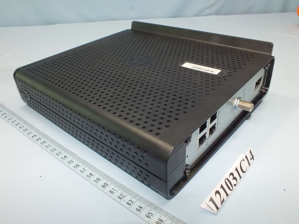
W5HSBG6782HH
Dec 25, 2012Wireless Gateway
Equipment Class
NII - Unlicensed National Information Infrastructure TX
W5HSBG6580-G228
Jul 30, 2012DOCSIS 3.0 Wi-Fi Gateway
Equipment Class
DTS - Digital Transmission System
W5HSBG6580A
Oct 18, 2010DOCSIS 3.0 Wi-Fi Gateway
Equipment Class
DTS - Digital Transmission System