W5HSBG6782HHWireless Gateway
ARRIS Taiwan, Ltd.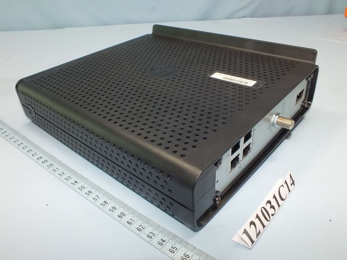
Click to zoom
Application Details
- Equipment Class
- NII - Unlicensed National Information Infrastructure TX
- Date of Grant
- Dec 25, 2012
- Application Purpose
- Original Equipment
- Date of Application
- Dec 25, 2012
- Equipment Note
- Wireless Gateway
- Frequency Range
- 5180.00000000 - 5240.00000000
- Company
- ARRIS Taiwan, Ltd.
- Country
- Taiwan
Documents & Files
Document Text
Text extracted from the exhibit documents filed with the FCC. Open a document above to read the original.
Users Manual
b User Guide Motorola SURFboard ® SBG6782 DOCSIS ® 3.0 Wireless Gateway DRAFT B ©2012 Motorola Mobility, LLC All rights reserved. MOTOROLA and the Stylized M Logo are trademarks or registered trademarks of Motorola Trademark Holdings, LLC. All other product or service names are the property of their respective owners. No part of this publication may be reproduced in any form or by any means or used to make any derivative work (such as translation, transformation, or adaptation) without written permission from Motorola Mobility, LLC. Motorola Mobility reserves the right to revise this publication and to make changes in content from time to time without obligation on the part of Motorola Mobility to provide notification of such revision or change. Motorola Mobility provides this guide without warranty of any kind, implied or expressed, including, but not limited to, the implied warranties of merchantability and fitness for a particular purpose. Motorola Mobility may make improvements or changes in the product(s) described in this manual at any time. DRAFT B SBG6782 DOCSIS 3.0 Wireless Gateway • User Guide i 589054-001-a i Safety and Regulatory Information IMPORTANT SAFETY INSTRUCTIONS Read This Before You Begin — When using your equipment, basic safety precautions should always be followed to reduce the risk of fire, electric shock, and injury to persons, including the following: • Read all of the instructions listed here and/or in the user manual before you operate this device. Give particular attention to all safety precautions. Retain the instructions for future reference. • This device must be installed and used in strict accordance with manufacturer’s instructions, as described in the user documentation that is included with the device. • Comply with all warning and caution statements in the instructions. Observe all warning and caution symbols that are affixed to this device. • To prevent fire or shock hazard, do not expose this device to rain or moisture. The device must not be exposed to dripping or splashing. Do not place objects filled with liquids, such as vases, on the device. • This device was qualified under test conditions that included the use of the supplied cables between system components. To ensure regulatory and safety compliance, use only the provided power and interface cables and install them properly. • Different types of cord sets may be used for connections to the main POWER supply circuit. Use only a main line cord that complies with all applicable device safety requirements of the country of use. • Installation of this device must be in accordance with national wiring codes and conform to local regulations. • Operate this device only from the type of power source indicated on the device’s marking label. If you are not sure of the type of power supplied to your home, consult your dealer or local power company. • Do not overload outlets or extension cords, as this can result in a risk of fire or electric shock. Overloaded AC outlets, extension cords, frayed power cords, damaged or cracked wire insulation, and broken plugs are dangerous. They may result in a shock or fire hazard. • Route power supply cords so that they are not likely to be walked on or pinched by items placed upon or against them. Pay particular attention to cords where they are attached to plugs and convenience receptacles, and examine the point where they exit from the device. • Place this device in a location that is close enough to an electrical outlet to accommodate the length of the power cord. • Place the device to allow for easy access when disconnecting the power cord of the device from the AC wall outlet. • Do not connect the plug into an extension cord, receptacle, or other outlet unless the plug can be fully inserted with no part of the blades exposed. • Place this device on a stable surface. • Avoid damaging the cable modem with static by touching the coaxial cable when it is attached to the earth- grounded coaxial cable-TV wall outlet. • Always first touch the coaxial cable connector on the cable modem when disconnecting or reconnecting the Ethernet cable from the cable modem or user’s PC. • It is recommended that the customer install an AC surge protector in the AC outlet to which this device is connected. This is to avoid damaging the device by local lightning strikes and other electrical surges. • Postpone installation until there is no risk of thunderstorm or lightning activity in the area. • Do not use this product near water: for example, near a bathtub, washbowl, kitchen sink or laundry tub, in a wet basement, or near a swimming pool. DRAFT B SBG6782 DOCSIS 3.0 Wireless Gateway • User Guide ii 589054-001-a • Do not cover the device or block the airflow to the device with any other objects. Keep the device away from excessive heat and humidity and keep the device free from vibration and dust. • Wipe the device with a clean, dry cloth. Never use cleaning fluid or similar chemicals. Do not spray cleaners directly on the device or use forced air to remove dust. • For added protection, unplug the device from the wall outlet and disconnect the cables to avoid damage to this device due to lightning and power surges. • Upon completion of any service or repairs to this device, ask the service technician to perform safety checks to determine that the device is in safe operating condition. • Do not open the device. Do not perform any servicing other than that contained in the installation and troubleshooting instructions. Refer all servicing to qualified service personnel. • This device should not be used in an environment that exceeds 104º F (40º C). SAVE THE ABOVE INSTRUCTIONS Note to CATV System Installer — This reminder is provided to call the CATV system installer’s attention to Article 820.93 and 820.100 of the National Electric Code, which provides guidelines for proper grounding and, in particular, specifies that the Coaxial cable shield shall be connected to the grounding system…
Text truncated - open the document above for the full version.
External Photos
Page 1 CONSTRUCTION PHOTOS OF EUT Model Name: SBG6782U‐HH Diagnostic Page 2 Page 11 Model Name: SBG6782U-HH Page 12 Page 21 Model Name: SBG6782-HH Page 22
ID Label/Location Info
5 OF 5SBG67821.000 7588516A1 STEP 6 INSTALL RIGHT ENCLOSURE HALF, BEZEL, AND REAR PANEL SCREWS STEP 7 ASSEMBLE UNIT LABEL 10 25 STEP 5 INSTALL WPS BUTTON PARTIAL VIEW SHOWN SCALE 2.000 12 (ITEM 8) 9 7 (ITEM 12) 15 REAR VIEW 4X
Internal Photos
Page 3 Model Name: SBG6782U‐HH Diagnostic Page 4 Page 5 Page 6 Page 7 Page 8 Page 9 Page 10 Page 13 Model Name: SBG6782U-HH Page 14 Page 15 Page 16 Page 17
Internal Photos
Page 18 Page 19 Page 20 Page 23 Model Name: SBG6782-HH Page 24 Page 25 Page 26 Page 27 Page 28 Page 29 Page 30
Operational Description
FCC ID: W5HSBG6782HH Report No.: RF121126C02 Operational Description This device is a Wireless Gateway, which operates in both 2.4GHz and 5GHz bands; the maximum data rate could be up to 450Mbps which OFDM technique. If the signal to noise radio is too poor which could not support 450Mbps, the 11Mbps data rate with DSSS technique will be applied. The transmitter of the EUT is powered by the 100-240Vac from AC plug. The antenna is Printed antenna with 3.5dBi gain The other instruction, please have a look at the users manual. FCC 15.407(c) states: The device shall automatically discontinue transmission in case of either absence of information to transmit or operational failure. These provisions are not intended to preclude the transmission of control or signaling information or the use of repetitive codes used by certain digital technologies to complete frame or burst intervals. Applicants shall include in their application for equipment authorization a description of how this requirement is met” Data transmission is always initiated by software, which is then pass down through the MAC, through the digital and analog baseband, and finally to the RF chip. Several special packets (ACKs, CTS, PSPoll, etc...) are initiated by the MAC. There are the only ways the digital baseband portion will turn on the RF transmitter, which it then turns off at the end of the packet. Therefore, the transmitter will be on only while one of the aforementioned packets are being transmitted.
RF Exposure Info
Report No.: SA121031C14A 1 of 6 Report Format Version 5.0.0 Reference No.: 121126C02 RF EXPOSURE REPORT REPORT NO.: SA121031C14A MODEL NO.: SBG6782-HH, SBG6782U-HH, SBG6782U-HH Diagnostic FCC ID: WH5SBG6782HH RECEIVED: Nov. 26, 2012 TESTED: Dec. 03 ~ Dec. 10, 2012 ISSUED: Dec. 12, 2012 APPLICANT: GENERAL INSTRUMENT OF TAIWAN, LTD. ADDRESS: 1, Lane 232 , Pao Chiao Road , Shin Dian, Taipei, Taiwan 231 , R.O.C ISSUED BY: Bureau Veritas Consumer Products Services (H.K.) Ltd., Taoyuan Branch LAB ADDRESS: No. 47, 14th Ling, Chia Pau Vil., Lin Kou Dist., New Taipei City, Taiwan, R.O.C. TEST LOCATION: No. 19, Hwa Ya 2nd Rd, Wen Hwa Tsuen, Kwei Shan Hsiang, Taoyuan Hsien 333, Taiwan, R.O.C. This report is for your exclusive use. Any copying or replication of this report to or for any other person or entity, or use of our name or trademark, is permitted only with our prior written permission. This report sets forth our findings solely with respect to the test samples identified herein. The results set forth in this report are not indicative or representative of the quality or characteristics of the lot from which a test sample was taken or any similar or identical product unless specifically and expressly noted. Our report includes all of the tests requested by you and the results thereof based upon the information that you provided to us. You have 60 days from date of issuance of this report to notify us of any material error or omission caused by our negligence, provided, however, that such notice shall be in writing and shall specifically address the issue you wish to raise. A failure to raise such issue within the prescribed time shall constitute your unqualified acceptance of the completeness of this report, the tests conducted and the correctness of the report contents. Unless specific mention, the uncertainty of measurement has been explicitly taken into account to declare the compliance or non-com pliance to the specification. Report No.: SA121031C14A 2 of 6 Report Format Version 5.0.0 Reference No.: 121126C02 TABLE OF CONTENTS RELEASE CONTROL RECORD ................................................................................................ 3 1. CERTIFICATION ............................................................................................................ 4 2. RF EXPOSURE .............................................................................................................. 5 2.1 LIMITS FOR MAXIMUM PERMISSIBLE EXPOSURE (MPE) ........................................ 5 2.2 MPE CALCULATION FORMULA ................................................................................... 5 2.3 CLASSIFICATION .......................................................................................................... 5 2.4 CALCULATION RESULT OF MAXIMUM CONDUCTED POWER ................................. 6 Report No.: SA121031C14A 3 of 6 Report Format Version 5.0.0 Reference No.: 121126C02 RELEASE CONTROL RECORD ISSUE NO. REASON FOR CHANGE DATE ISSUED SA121031C14A Original release Dec. 12, 2012 Report No.: SA121031C14A 5 of 6 Report Format Version 5.0.0 Reference No.: 121126C02 2. RF EXPOSURE 2.1 LIMITS FOR MAXIMUM PERMISSIBLE EXPOSURE (MPE) FREQUENCY RANGE (MHz) ELECTRIC FIELD STRENGTH (V/m) MAGNETIC FIELD STRENGTH (A/m) POWER DENSITY (mW/cm 2 ) AVERAGE TIME (minutes) LIMITS FOR GENERAL POPULATION / UNCONTROLLED EXPOSURE 300-1500 ... ... F/1500 30 1500-100,000 ... ... 1.0 30 F = Frequency in MHz 2.2 MPE calculation Formula Pd = (Pout*G) / (4*pi*r 2 ) where Pd = power density in mW/cm 2 Pout = output power to antenna in mW G = gain of antenna in linear scale Pi = 3.1416 R = distance between observation point and center of the radiator in cm 2.3 Classification The antenna of this product, under normal use condition, is at least 20cm away from the body of the user. So, this device is classified as Mobile Device. Report No.: SA121031C14A 6 of 6 Report Format Version 5.0.0 Reference No.: 121126C02 2.4 Calculation result of maximum conducted power FREQUENCY BAND (MHz) MAX POWER (dBm) ANTENNA GAIN (dBi) DISTANCE (cm) POWER DENSITY (mW/cm 2 ) LIMIT (mW/cm 2 ) 2412-2462 27.59 9.17 20 0.943 1 5180-5240 16.34 8.27 20 0.058 1 5745-5825 28.48 8.27 20 0.941 1 NOTE: 2.4GHz: Directional gain = 4.4dBi + 10log(3) = 9.17dBi 5.0GHz: Directional gain = 3.5dBi + 10log(3) = 8.27dBi
Test Report
Report No.: RF121031C14A 1 of 79 Report Format Version 5.1.0 Reference No.: 121126C02 FCC TEST REPORT (15.247) REPORT NO.: RF121031C14A MODEL NO.: SBG6782-HH (Refer to item 3.1 for more details) FCC ID: W5HSBG6782HH RECEIVED: Nov. 26, 2012 TESTED: Dec. 04 ~ Dec. 10, 2012 ISSUED: Dec. 12, 2012 APPLICANT: GENERAL INSTRUMENT OF TAIWAN, LTD. ADDRESS: 1, Lane 232 , Pao Chiao Road , Shin Dian, Taipei, Taiwan 231 , R.O.C ISSUED BY: Bureau Veritas Consumer Products Services (H.K.) Ltd., Taoyuan Branch LAB ADDRESS: No. 47, 14th Ling, Chia Pau Vil., Lin Kou Dist., New Taipei City, Taiwan, R.O.C. TEST LOCATION: No. 19, Hwa Ya 2nd Rd, Wen Hwa Tsuen, Kwei Shan Hsiang, Taoyuan Hsien 333, Taiwan, R.O.C. This report is for your exclusive use. Any copying or replication of this report to or for any other person or entity, or use of our name or trademark, is permitted only with our prior written permission. This report sets forth our findings solely with respect to the test samples identified herein. The results set forth in this report are not indicative or representative of the quality or characteristics of the lot from which a test sample was taken or any similar or identical product unless specifically and expressly noted. Our report includes all of the tests requested by you and the results thereof based upon the information that you provided to us. You have 60 days from date of issuance of this report to notify us of any material error or omission caused by our negligence, provided, however, that such notice shall be in writing and shall specifically address the issue you wish to raise. A failure to raise such issue within the prescribed time shall constitute your unqualified acceptance of the completeness of this report, the tests conducted and the correctness of the report contents. Unless specific mention, the uncertainty of measurement has been explicitly taken into account to declare the com pliance or non-compliance to the specification. This report should not be used by the client to claim product certification, approval, or endorsement by TAF or any government agencies. Report No.: RF121031C14A 2 of 79 Report Format Version 5.1.0 Reference No.: 121126C02 TABLE OF CONTENTS RELEASE CONTROL RECORD ......................................................................................... 5 1. CERTIFICATION ...................................................................................................... 6 2. SUMMARY OF TEST RESULTS ............................................................................. 7 2.1 MEASUREMENT UNCERTAINTY .......................................................................... 7 3. GENERAL INFORMATION ...................................................................................... 8 3.1 GENERAL DESCRIPTION OF EUT ........................................................................ 8 3.2 DESCRIPTION OF TEST MODES ........................................................................ 10 3.2.1 TEST MODE APPLICABILITY AND TESTED CHANNEL DETAIL ......................... 11 3.3 DESCRIPTION OF SUPPORT UNITS .................................................................. 15 3.3.1 CONFIGURATION OF SYSTEM UNDER TEST ................................................... 16 3.4 GENERAL DESCRIPTION OF APPLIED STANDARDS ....................................... 17 4. TEST TYPES AND RESULTS (FOR 2.4GHz BAND) ............................................ 18 4.1 RADIATED EMISSION AND BANDEDGE MEASUREMENT ................................ 18 4.1.1 LIMITS OF RADIATED EMISSION AND BANDEDGE MEASUREMENT ............. 18 4.1.2 TEST INSTRUMENTS .......................................................................................... 19 4.1.3 TEST PROCEDURES ........................................................................................... 20 4.1.4 DEVIATION FROM TEST STANDARD ................................................................. 20 4.1.5 TEST SETUP ........................................................................................................ 21 4.1.6 EUT OPERATING CONDITIONS .......................................................................... 21 4.1.7 TEST RESULTS .................................................................................................... 22 4.2 CONDUCTED EMISSION MEASUREMENT ........................................................ 35 4.2.1 LIMITS OF CONDUCTED EMISSION MEASUREMENT...................................... 35 4.2.2 TEST INSTRUMENTS .......................................................................................... 35 4.2.3 TEST PROCEDURES ........................................................................................... 36 4.2.4 DEVIATION FROM TEST STANDARD ................................................................. 36 4.2.5 TEST SETUP ........................................................................................................ 36 4.2.6 EUT OPERATING CONDITIONS .......................................................................... 36 4.2.7 TEST RESULTS .................................................................................................... 37 4.3 6dB BANDWIDTH MEASUREMENT .................................................................... 39 4.3.1 LIMITS OF 6dB BANDWIDTH MEASUREMENT .................................................. 39 4.3.2 TEST SETUP ........................................................................................................ 39 4.3.3 TEST INSTRUMENTS .......................................................................................... 39 4.3.4 TEST PROCEDURE ............................................................................................. 39 4.3.5 DEVIATION FROM TEST STANDARD ................................................................. 39 4.3.6 EUT OPERATING CONDITIONS .......................................................................... 39 4.3.7 TEST RESULTS ..................................…
Text truncated - open the document above for the full version.
Test Report
Report No.: RF121031C14A-1 1 of 67 Report Format Version 5.1.0 Reference No.: 121126C02 FCC TEST REPORT (15.407) REPORT NO.: RF121031C14A-1 MODEL NO.: SBG6782-HH (Refer to item 3.1 for more details) FCC ID: W5HSBG6782HH RECEIVED: Nov. 26, 2012 TESTED: Dec. 03 ~ Dec. 07, 2012 ISSUED: Dec. 12, 2012 APPLICANT: GENERAL INSTRUMENT OF TAIWAN, LTD. ADDRESS: 1, Lane 232 , Pao Chiao Road , Shin Dian, Taipei, Taiwan 231 , R.O.C ISSUED BY: Bureau Veritas Consumer Products Services (H.K.) Ltd., Taoyuan Branch LAB ADDRESS: No. 47, 14th Ling, Chia Pau Vil., Lin Kou Dist., New Taipei City, Taiwan, R.O.C. TEST LOCATION: No. 19, Hwa Ya 2nd Rd, Wen Hwa Tsuen, Kwei Shan Hsiang, Taoyuan Hsien 333, Taiwan, R.O.C. This report is for your exclusive use. Any copying or replication of this report to or for any other person or entity, or use of our name or trademark, is permitted only with our prior written permission. This report sets forth our findings solely with respect to the test samples identified herein. The results set forth in this report are not indicative or representative of the quality or characteristics of the lot from which a test sample was taken or any similar or identical product unless specifically and expressly noted. Our report includes all of the tests requested by you and the results thereof based upon the information that you provided to us. You have 60 days from date of issuance of this report to notify us of any material error or omission caused by our negligence, provided, however, that such notice shall be in writing and shall specifically address the issue you wish to raise. A failure to raise such issue within the prescribed time shall constitute your unqualified acceptance of the completeness of this report, the tests conducted and the correctness of the report contents. Unless specific mention, the uncertainty of measurement has been explicitly taken into account to declare the com pliance or non-compliance to the specification. This report should not be used by the client to claim product certification, approval, or endorsement by TAF or any government agencies. Report No.: RF121031C14A-1 2 of 67 Report Format Version 5.1.0 Reference No.: 121126C02 TABLE OF CONTENTS RELEASE CONTROL RECORD .............................................................................................. 4 1. CERTIFICATION........................................................................................................... 5 2. SUMMARY OF TEST RESULTS .................................................................................. 6 2.1 MEASUREMENT UNCERTAINTY ................................................................................ 6 3. GENERAL INFORMATION ........................................................................................... 7 3.1 GENERAL DESCRIPTION OF EUT ............................................................................. 7 3.2 DESCRIPTION OF TEST MODES ............................................................................... 8 3.2.1 TEST MODE APPLICABILITY AND TESTED CHANNEL DETAIL ............................... 9 3.3 DUTY CYCLE OF TEST SIGNAL ............................................................................... 11 3.4 DESCRIPTION OF SUPPORT UNITS ....................................................................... 12 3.4.1 CONFIGURATION OF SYSTEM UNDER TEST ........................................................ 13 3.5 GENERAL DESCRIPTION OF APPLIED STANDARDS ............................................ 14 4. TEST TYPES AND RESULTS .................................................................................... 15 4.1 RADIATED EMISSION AND BANDEDGE MEASUREMENT ..................................... 15 4.1.1 LIMITS OF RADIATED EMISSION AND BANDEDGE MEASUREMENT .................. 15 4.1.2 LIMITS OF UNWANTED EMISSION OUT OF THE RESTRICTED BANDS .............. 15 4.1.3 TEST INSTRUMENTS ................................................................................................ 16 4.1.4 TEST PROCEDURES ................................................................................................ 17 4.1.5 DEVIATION FROM TEST STANDARD ...................................................................... 17 4.1.6 TEST SETUP .............................................................................................................. 18 4.1.7 EUT OPERATING CONDITION .................................................................................. 18 4.1.8 TEST RESULTS ......................................................................................................... 19 4.2 CONDUCTED EMISSION MEASUREMENT ............................................................. 34 4.2.1 LIMITS OF CONDUCTED EMISSION MEASUREMENT ........................................... 34 4.2.2 TEST INSTRUMENTS ................................................................................................ 34 4.2.3 TEST PROCEDURES ................................................................................................ 35 4.2.4 DEVIATION FROM TEST STANDARD ...................................................................... 35 4.2.5 TEST SETUP .............................................................................................................. 35 4.2.6 EUT OPERATING CONDITIONS ............................................................................... 35 4.2.7 TEST RESULTS ......................................................................................................... 36 4.3 PEAK TRANSMIT POWER MEASUREMENT ........................................................... 40 4.3.1 LIMITS OF PEAK TRANSMIT POWER MEASUREMENT ......................................... 40 4.3.2 TEST SETUP .............................................................................................................. 40 4.3.3 TEST INSTRUMENTS ................................................................................................ 40 4.3.4 TEST PRO…
Text truncated - open the document above for the full version.
Test Setup Photos
1 PHOTOGRAPHS OF THE TEST CONFIGURATION CONDUCTED EMISSION TEST 2 RADIATED EMISSION TEST
Contact Information
Applicant
Terry Lin(Sr. Engineer)
Test Firm
Bureau Veritas CPS (H.K.) Ltd., Taoyuan BranchRichard Chen
Technical Specifications
| # | Rule Parts | Frequency Range | Power Output |
|---|---|---|---|
| 1 | 15E | 5.18 GHz - 5.24 GHz | 43.00 mW |
Other Applications from ARRIS Taiwan, Ltd.

W5HSVG7782HH
Apr 10, 2013Wireless voice cable modem gateway
Equipment Class
DTS - Digital Transmission System
W5HSVG6582G217
Mar 04, 2013wireless voice gateway
Equipment Class
DTS - Digital Transmission System
W5HSBG6580-G228
Jul 30, 2012DOCSIS 3.0 Wi-Fi Gateway
Equipment Class
DTS - Digital Transmission System
W5HSBG6580A
Oct 18, 2010DOCSIS 3.0 Wi-Fi Gateway
Equipment Class
DTS - Digital Transmission System
W5HSBG6580
Jan 17, 2010DOCSIS 3.0 Wi-Fi Gateway
Equipment Class
NII - Unlicensed National Information Infrastructure TX