W66-E18-000008Wifi camera
PRO TV DEVELOPMENT INC.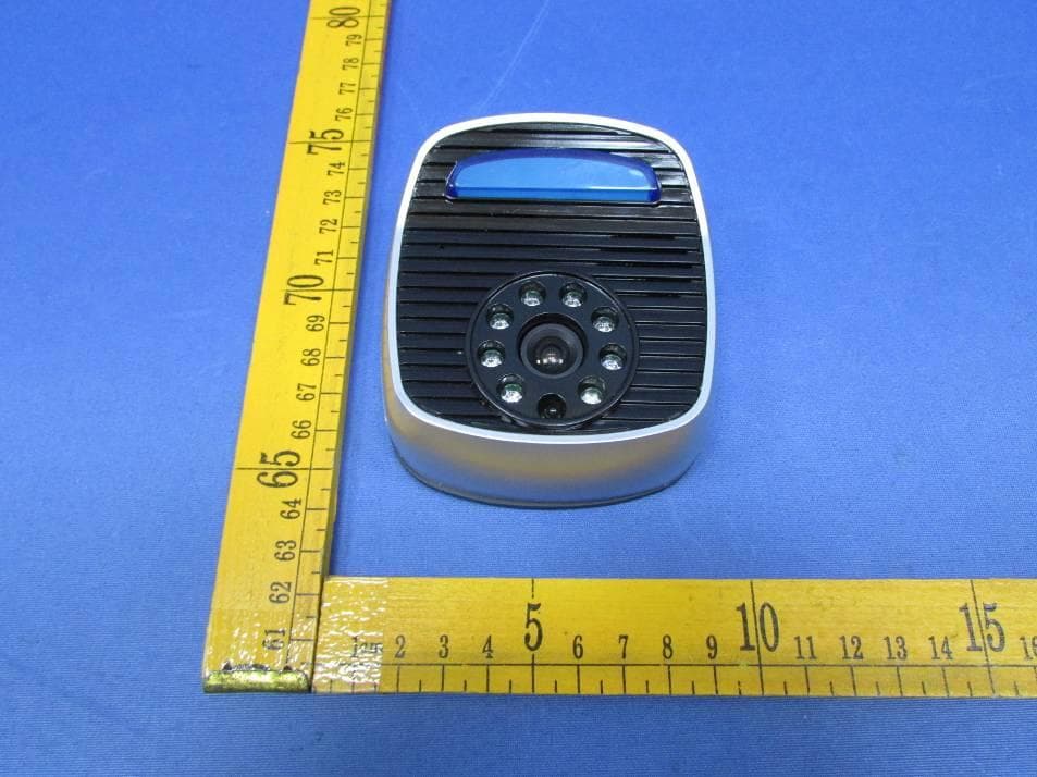
Click to zoom
Application Details
- Equipment Class
- DTS - Digital Transmission System
- Date of Grant
- Nov 11, 2015
- Application Purpose
- Original Equipment
- Date of Application
- Nov 11, 2015
- Equipment Note
- Wifi camera
- Frequency Range
- 2412.00000000 - 2462.00000000
- Company
- PRO TV DEVELOPMENT INC.
- Country
- Taiwan
Documents & Files
Document Text
Text extracted from the exhibit documents filed with the FCC. Open a document above to read the original.
Users Manual
Step 10: The setting window is jumping on the screen. Then please select “Wi-Fi Setting” item. Thenyouwill seethe screenwas shown at right side: QR code DP-106 SIP IP video door phone SSID (Service Set I dentifier)is the name of wi reless networkand should not be confused with thehost name of the wireless accesspoint. The name is set by t he networkadministrator who configures the router. All wireless devices ona WLAN must employ t he same SSID in order to communicate with each other. The SSID is a sequence of alphanumeric characters (letters or numbers) and have a maximumlength of 32 characters. WPA2PSK(Wi-Fi Protected Access2, Pre-Shared Key)is a more powerful security technology for Wi-Fi networks. WPA2PSKis basically an authentication mechanismin which users provide some form of credentials to verify t hat t hey should be allowed access t o a network. The AES(Advanced Encryption Standard) is a specification for the encryption of electronic data. SSID (Service Set I dentifier)is the name of wi reless networkand should not be confused with thehost name of the wireless accesspoint. The name is set by t he networkadministrator who configures the router. All wireless devices ona WLAN must employ t he same SSID in order to communicate with each other. The SSID is a sequence of alphanumeric characters (letters or numbers) and have a maximumlength of 32 characters. WPA2PSK(Wi-Fi Protected Access2, Pre-Shared Key)is a more powerful security technology for Wi-Fi networks. WPA2PSKis basically an authentication mechanismin which users provide some form of credentials to verify t hat t hey should be allowed access t o a network. The AES(Advanced Encryption Standard) is a specification for the encryption of electronic data. Ifother usersharesDP-106door phone with you, t he door phone picturewill appearin the areaof You can provideyour Q R code to other user who will share the DP-106door phone with you. Step1. To drillfour holes for the plastic wall plug in place, and then put the plastic wall plug into hole. Step2.Put the fixed panel in place and (inside the house) connecting cable go through middle hole (for connecting the unit electricwire nest step). Use the four screws fixed the panel. Step3.The unit have red (positive pole) and blue (negative pole)two wire line. Ensure correct connect to the inside house wire. And then buckle the unit on the panel. Screw fixed it in the bottom positon. And install it on yoursmatphone 2.. Ruing Door guard Application and Create a New Account Screw Mid hole for connecting cable Electricwire Fixed panel In the bottom position for screw hole Part1. Unit installationPart2. APP operating guide Step 7: Click the “Scan QR Code” to Scan the QR code which stick on the unit Then you will see the successful information after scanning. Please press “ok”bar. At the same time, you will see the active codeof your door phone display on the screen. 4-a Wi-Fi setting for Android 4-b Wi-Fi Setting for IOS After step 15, you have to go to settingfunction of your iPhone or iPad. Then select DP-106 in Wi-Fi display zonethat shown as right side. Go back DoorGuardagain 5. Click and view the video of Door Phone on your smart phone. 6.Share setting E18-000008 Step 1: Please click “ INSTAL” Lbutton on t he screen of your smartphone. 1.Download “Door Guard” APP form Apple store or Google Play store. Step 2: Create a new account Step 3: Input your accountname and password Step 4: When you have finished the input data, please click on “Send” button. Step 5: Then you will see t he success message of a new account registrationon t he screen. And cli ckOkbar here. No any doorphone shows on the screen now. Step 6: You need to add your new doorphone. Pleasecli ck Add DoorPhonebutt on at t he bottomof screen. If you do NOT want t o receiverany call fromdoor phone, p lease cli ck Settingbutt on. 3. Add your New Door Phone Step 8: Congratulation! The DP-106 door phone is addedsuccessful. Step 9: Click this gear icon for setting Wi-Fi network. Step 11: Input SSID and Key. Step 12: You alsocan do advanced setting to add authentication and encryption mechanism. Step 13: You will see t he completed information display on t he screen. Then cli ckFinish butt on to complete t he setting. Finishing t he Wi-Fi setting, the DP-106 SIP IP video doorphone will restart automatically. Step 14: Congratulation! The DP-106 door phone is addedsuccessful. Step 15: Click this gear icon for setting Wi-Fi network. Step 15: The setting window is jumping on the screen. Then please select “Wi-Fi Setting” item. Step 16: Input SSID and Key. Step 17: You alsocan do advanced setting to add authentication and encryption mechanism. Step 18: You will see the completed information display on the screen. Then click “Finish” button to complete the setting. Finishing the Wi-Fi setting, the DP-106 SIP IP video door phone will restart automatically. Step 19: The installation is successful. Please click on this area to view the real time image of door phone and talk to the person who at your door. Hereby, PRO TV DEVELOPMENT INC., declares that this Wifi camera is In compliance with the essential requirements and other relevant provisions of Directive 1999/5/EC. Environment friendly disposal 0700 FCC Warning: This device complies with part 15 of the FCC Rules. Operation is subject to the following two conditions: (1) This device may not cause harmful interference, and (2) this device must accept any interference received, including interference that may cause undesired operation. Any Changes or modifications not expressly approved by the party responsible for compliance could void the user's authority to operate the equipment. Note: This equipment has been tested and found to comply with the limits for a Class B digital device, pursuant to part 15 of the FCC Rules. These limits are designed to provide reasonable protection against harmful interference in a residential installation. This equipment generates uses and can radiate radio fre…
Text truncated - open the document above for the full version.
External Photos
Waltek Services (Shenzhen) Co.,Ltd. http://www.waltek.com.cn Photographs - Constructional Details Model E18-000008–External View Model: E18-000008 Waltek Services (Shenzhen) Co.,Ltd. http://www.waltek.com.cn Model: E18-000006
ID Label/Location Info
PRO TV DEVELOPMENT INC. FCC ID: W66-E18-000008 Input: DC 12V, 500Ma 0700 label location/Label Sample
Internal Photos
Waltek Services (Shenzhen) Co.,Ltd. http://www.waltek.com.cn Model E18-000008– Internal View Model: E18-000008 ANT Waltek Services (Shenzhen) Co.,Ltd. http://www.waltek.com.cn Waltek Services (Shenzhen) Co.,Ltd. http://www.waltek.com.cn Waltek Services (Shenzhen) Co.,Ltd. http://www.waltek.com.cn Waltek Services (Shenzhen) Co.,Ltd. http://www.waltek.com.cn Waltek Services (Shenzhen) Co.,Ltd. http://www.waltek.com.cn ======End of Report======
Test Report
Waltek Services (Shenzhen) Co.,Ltd. http://www.waltek.com.cn Page 1 of 67 TEST REPORT Referen ce No. .................... : WTS15S0934272E FCC ID................................. : W66-E18-000008 Applicant ............................ : PRO TV DEVELOPMENT INC. Address .............................. : 11F-1, NO.15, SEC. 4, CHUNG HSIAO E RD., TAIPEI, TAIWAN Manufacturer ..................... : PRO TV DEVELOPMENT INC. Address .............................. : 11F-1, NO.15, SEC. 4, CHUNG HSIAO E RD., TAIPEI, TAIWAN Product Name .................... : Wifi camera Model No. ........................... : E18-00009, E18-000008, E18-000006, E18-000005 Standards ........................... : FCC CFR47 Part 15 C Section 15.247:2014 Date of Receipt sample ..... : Sep. 22, 2015 Date of Test ........................ : Oct. 08 – Nov. 12, 2015 Date of Issue ...................... : Nov. 12, 2015 Test Result ......................... : Pass Remarks: The re sults shown in this test report refer only to the sample(s) tested, this test report cannot be reproduced, except in full, without prior written permission of the company. The report would be invalid without specific stamp of test institute and the signatures of compiler and approver. Prepared By: Waltek Services (Shenzhen) Co., Ltd. Address: 1/F., Fukangtai Building, West Baima Road, Songgang Street, Baoan District, Shenzhen, Guangdong, China Tel :+86-755-83551033 Fax:+86-755-83552400 Compiled by: Approved by: Zero Zhou / Test Engineer Philo Zhong / Manager Reference No.: WTS15S0934272E Page 2 of 67 Waltek Services (Shenzhen) Co.,Ltd. http://www.waltek.com.cn 2 Test Summary Test Items Test Requirement Result Radiated Emissions 15.247 15.205(a) 15.209(a) PASS Conducted Emissions 15.207(a) PASS 6dB Bandwidth 15.247(a)(2) PASS Maximum Peak Output Power 15.247(b)(3),(4) PASS Power Spectral Density 15.247(e) PASS Band Edge 15.247(d) PASS Antenna Requirement 15.203 PASS Maximum Permissible Exposure (Exposure of Humans to RF Fields) 1.1307(b)(1) PASS Reference No.: WTS15S0934272E Page 3 of 67 Waltek Services (Shenzhen) Co.,Ltd. http://www.waltek.com.cn 3 Contents Page 1 COVER PAGE ........................................................................................................................................... 1 2 TEST SUMMARY ................................................................................................................................................ 2 3 CONTENTS .......................................................................................................................................................... 3 4 GENERAL INFORMATION ................................................................................................................................ 5 4.1 GENERAL DESCRIPTION OF E.U.T. .............................................................................................................. 5 4.2 DETAILS OF E.U.T. ....................................................................................................................................... 5 4.3 CHANNEL LIST ............................................................................................................................................... 5 4.4 TEST MODE ................................................................................................................................................... 6 4.5 TEST FACILITY ............................................................................................................................................... 7 5 EQUIPMENT USED DURING TEST ................................................................................................................ 8 5.1 EQUIPMENTS LIST ......................................................................................................................................... 8 5.2 DESCRIPTION OF SUPPORT UNITS ............................................................................................................... 9 5.3 MEASUREMENT UNCERTAINTY ..................................................................................................................... 9 5.4 TEST EQUIPMENT CALIBRATION ................................................................................................................... 9 6 CONDUCTED EMISSION ................................................................................................................................ 10 6.1 E.U.T. OPERATION ..................................................................................................................................... 10 6.2 EUT SETUP ................................................................................................................................................. 10 6.3 MEASUREMENT DESCRIPTION .................................................................................................................... 10 6.4 CONDUCTED EMISSION TEST RESULT ....................................................................................................... 11 7 RADIATED EMISSIONS................................................................................................................................... 13 7.1 EUT OPERATION ......................................................................................................................................... 13 7.2 TEST SETUP ................................................................................................................................................ 14 7.3 SPECTRUM ANALYZER SETUP .................................................................................................................... 15 7.4 TEST PROCEDURE ...................................................................................................................................... 16 7.5 CORRECTED AMPLITUDE & MARGIN CALCULATION ................................................................................... 16 7.6 …
Text truncated - open the document above for the full version.
Test Setup Photos
Waltek Services (Shenzhen) Co.,Ltd. http://www.waltek.com.cn 14 Photographs – Model E18-000008 Test Setup 14.1 Radiated Emission Test frequency from 30MHz to 1GHz at Test Site 2# Test frequency above 1GHz at Test Site 1# Waltek Services (Shenzhen) Co.,Ltd. http://www.waltek.com.cn 14.2 Conducted Emission at Test Site 1#
Contact Information
Applicant
NIANZU TANG(President)
Test Firm
Waltek Services(Shenzhen) Co., Ltd.philo zhong
Technical Specifications
| # | Rule Parts | Frequency Range | Power Output |
|---|---|---|---|
| 1 | 15C | 2.41 GHz - 2.46 GHz | 4.90 mW |
Other Applications from PRO TV DEVELOPMENT INC.
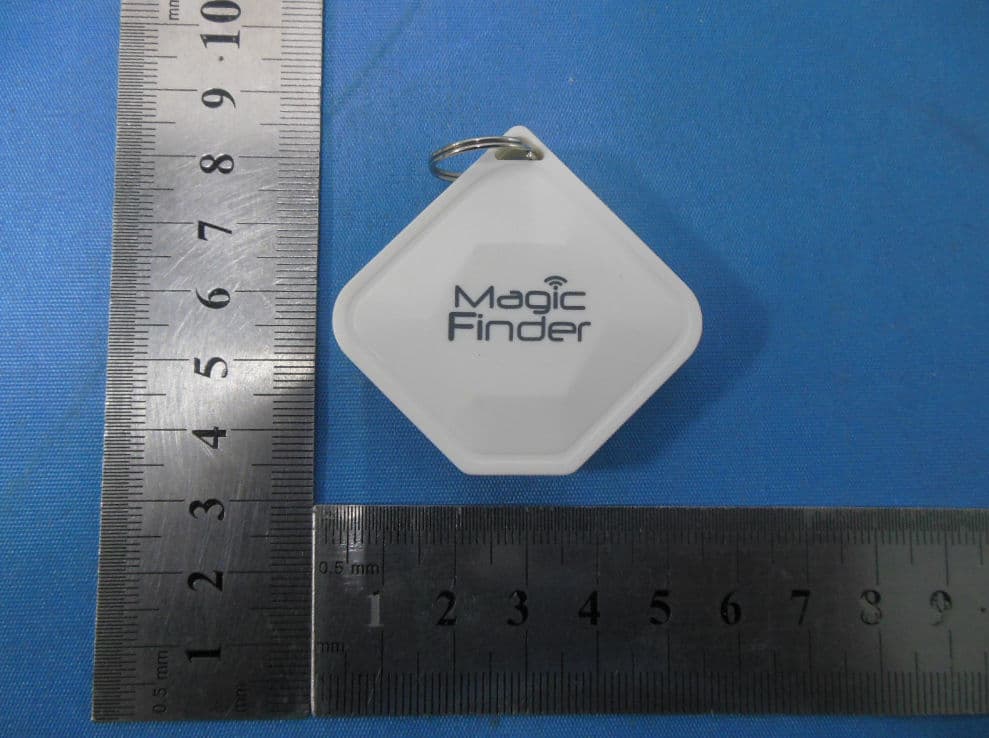
W66MF-MO
Jul 19, 2015Magic Finder
Equipment Class
DTS - Digital Transmission System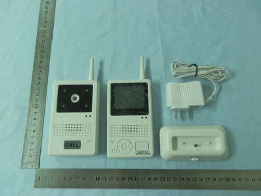
W66-8553T
Sep 08, 2011VIDEO DOORBELL
Equipment Class
DXX - Part 15 Low Power Communication Device Transmitter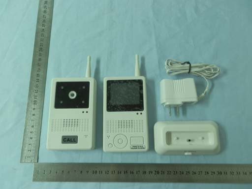
W66-8553R
Sep 08, 2011VIDEO DOORBELL
Equipment Class
DXX - Part 15 Low Power Communication Device Transmitter