W7DMB220Power Failure Detector
Wireless Environment LLC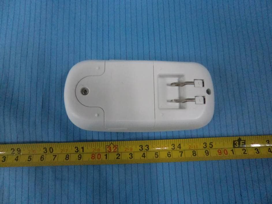
Click to zoom
Application Details
- Equipment Class
- DSC - Part 15 Security/Remote Control Transmitter
- Date of Grant
- Aug 15, 2011
- Application Purpose
- Original Equipment
- Date of Application
- Aug 15, 2011
- Equipment Note
- Power Failure Detector
- Frequency Range
- 433.92000000 - 433.92000000
- Company
- Wireless Environment LLC
- Country
- United States
Documents & Files
Document Text
Text extracted from the exhibit documents filed with the FCC. Open a document above to read the original.
Users Manual
Thank you for purchasing the Mr. Beams™ Power Outage Detector and Remote (POD). The POD works with the Mr. Beams Power Outage Lights to automatically activate lights in the event of a power Outage. One POD can activate dozens of Power Outage Lights. We are certain your Mr. Beams Power Outage Lighting System will contribute to a safer environment and provide light where you need it at a very reasonable cost. ENCLOSED YOU WILL FIND: • Power Outage Detector & Remote • Rechargeable 3.6V NiMH Battery Item MB220 INSTRUCTION GUIDE MB220 Power Outage Detector Features: Power-Outage Activated – Your Power Out- age Detector works with the MB785 and MB985 Power Outage Lights and has a transmitter that will activate all Power Outage lights instantly when a power outage is detected. Flashlight– The POD has a bright LED for use as a flashlight. This flashlight automatically activates during a power Outage. Remote Control Feature—Your Power Outage Detector can control all Power Outage Lights as a remote control. Low Battery Indicator—The red LED on your light flashes when it is time to recharge batteries. WARNING • RISK OF ELECTRICAL SHOCK. For adult use only. This product is a light that uses 120V AC power. This product is not a toy and should not be stored or used in locations accessible to children. For safe use: plug into exposed wall outlet where device is ventilated and cannot contact bed coverings or other materials that may present a fire hazard. Do not use with extension cords. • Follow battery instructions for proper disposal and cautions. Remove screw on battery door as shown in Illustration 1. Remove battery door from back of POD (Illustration 2). IMPORTANT NOTES: • Auto Shut-Off Feature: If a power Outage occurs, the POD and Power Out- age Lights will activate. If a button on the POD is not pressed, all lights will turn off in 30 minutes to conserve battery life. • For instructions on Power Outage Lights, please refer to their User Manuals. • POD cannot charge while flashlight is on - therefore use as nightlight is not recommended. INSTALLATION INSTRUCTIONS Mr. Beams 57 E. Washington St. Chagrin Falls, OH 44035 877.298.9082 www.mrbeams.com BEFORE YOU PLUG IN YOUR POWER OUTAGE DETECTOR (POD): Illustration 1 Illustration 3 Illustration 2 Illustration 4 POWER OUTAGE DETECTOR + REMOTE + RECHARGEABLE FLASHLIGHT Install Battery by inserting the battery clip into the slot on the POD as shown in Illustration 3. Tuck wires in, replace bat- tery door and insert screw (Illustration 1). Retract plug on POD (Illustration 4) and plug into electrical outlet (Illustration 5). For safe use: plug into exposed wall outlet where de- vice is ventilated and cannot contact bed coverings or other materials that may present a fire hazard. LIMITED WARRANTY The product you have purchased is guaranteed against defects in workmanship and materials for the period stated on the package. Warranties implied by law are subject to the same time period limitation. Some states do not allow limitations on how long an implied warranty lasts, so this time limitation may not apply to you. If the product fails due to a manufac- turing defect during normal use, return the product and dated sales receipt to the store where purchased for replacement OR send the product and the dated sales receipt to the address above. Not Covered – Batteries are not covered by this warranty. Repair service, adjustment and calibration due to misuse, abuse or negligence are not covered by this warranty. Unauthorized service or modification to this product or of any furnished components will void this warranty in its entirety. This warranty does not include reimbursement for incon- venience, installation, set-up time, loss of use, postage, unauthorized service, or other products used in conjunction with, but are not supplied by, Wireless Environment. This warranty gives you specific legal rights, and you may also have other rights which vary. Removing the POD from the electrical outlet simulates a power Outage (Illustration 6). This turns on the Flashlight and all Power Out- age Lights that you have installed . Placing the POD back into a live electrical outlet will turn the flashlight off as well as all Power Outage Lights. In the event of a power Outage, the POD will immediately send a signal to turn on all Power Out- age Lights. The POD will also turn on its internal LED to serve as a flashlight (Illustration 7). OPERATION OF THE POWER OUTAGE DETECTOR (POD): To operate the flashlight, push the round button on the POD (Illustration 10). Your POD also serves as a remote control for all of the Power Outage Lights. The curved button on the top right turns all lights on (Illustration 8). The curved button on the top left of the POD turns all lights off (Illustration 9). Illustration 5 Illustration 6 Illustration 8 Illustration 7 Illustration 9 Illustration 10 CAUTION Risk of Electric Shock Dry location use only INSTRUCTIONS PERTAINING TO A RISK OF FIRE, ELECTRIC SHOCK, OR INJURY TO PERSONS IMPORTANT SAFETY INSTRUCTIONS WARNING – a) Read all the instructions before using the appliance. b) To reduce the risk of injury, close supervision is necessary when an appliance is used near children. c) Do not use outdoors. d) To reduce the risk of electrical shock, do not put the unit in water or other liquid. Do not place or store appliance where it can fall or be pulled into a tub or sink. When using electric appliances, basic precautions should always be followed, including the following: SAVE THESE INSTRUCTIONS Any Changes or modifications not expressly approved by the party responsible for compliance could void the user's authority to operate the equipment. For household use only. The battery is not intended to be replaced by user. This device complies with Part 15 of the FCC Rules. Operation is subject to the following two conditions: (1) this device may not cause harmful interference, and (2) this device must accept any interference received, including interfe…
Text truncated - open the document above for the full version.
External Photos
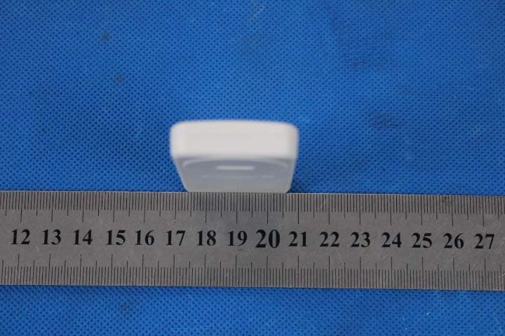
EXHIBIT B - EUT EXTERNAL PHOTOGRAPHS EUT– Top View EUT– Bottom View
ID Label/Location Info
EXHIBIT A - FCC ID LABELING AND LOCATION FCC ID Label FCC ID Label Location
Internal Photos
EXHIBIT C - EUT INTERNAL PHOTOGRAPHS EUT – Battery off View EUT – Cover off View EUT - Main Board Top View Antenna EUT - Main Board Bottom View
Test Report
Note: This test report is prepared for the customer shown above and for the equipment described herein. It may not be duplicated or used in part without prior written consent from Bay Area Compliance Laboratories Corp. This report must not be used by the customer to claim product certification, approval, or endorsement by NVLAP*, or any agency of the Federal Government. * This report contains data that are not covered by the NVLAP accreditation and are marked with an asterisk “★” (Rev.2) TEST REPORT For Wireless Environment LLC 151 Innovation Drive, Elyria, Ohio 44035, USA FCC Part 15.231 FCC ID: W7DMB220 Report Type: Original Report Product Type: Power Failure Detector Test Engineer: Eric Lee Report Number: RDG110616001-00 Report Date: 2011-07-29 Reviewed By: Merry Zhao EMC Engineer Test Laboratory: Bay Area Compliance Laboratories Corp. (Shenzhen) 6/F, the 3rd Phase of WanLi Industrial Building, ShiHua Road, FuTian Free Trade Zone Shenzhen, Guangdong, China Tel: +86-755-33320018 Fax: +86-755-33320008 www.baclcorp.com.cn Bay Area Compliance Laboratories Corp. (Shenzhen) FCC ID: W7DMB220 Report No.: RDG110616001-00 Page 2 of 24 FCC Part15.231 Test Report TABLE OF CONTENTS GENERAL INFORMATION.......................................................................................................................................4 PRODUCT DESCRIPTION FOR EQUIPMENT UNDER TEST (EUT) ....................................................................................4 OBJECTIVE...................................................................................................................................................................4 RELATED SUBMITTAL(S)/GRANT(S).............................................................................................................................4 TEST METHODOLOGY..................................................................................................................................................4 TEST FACILITY.............................................................................................................................................................4 SYSTEM TEST CONFIGURATION ..........................................................................................................................6 JUSTIFICATION.............................................................................................................................................................6 SPECIAL ACCESSORIES.................................................................................................................................................6 EQUIPMENT MODIFICATIONS.......................................................................................................................................6 CONFIGURATION OF TEST SETUP.................................................................................................................................6 BLOCK DIAGRAM OF TEST SETUP................................................................................................................................6 SUMMARY OF TEST RESULTS ...............................................................................................................................7 FCC §15.203 - ANTENNA REQUIREMENT.............................................................................................................8 APPLICABLE STANDARD..............................................................................................................................................8 FCC §15.107 (A) – AC LINE CONDUCTED EMISSIONS ......................................................................................9 APPLICABLE STANDARD..............................................................................................................................................9 MEASUREMENT UNCERTAINTY....................................................................................................................................9 EUT SETUP..................................................................................................................................................................9 EMI TEST RECEIVER SETUP.......................................................................................................................................10 TEST PROCEDURE......................................................................................................................................................10 TEST EQUIPMENT LIST AND DETAILS.........................................................................................................................10 TEST RESULTS SUMMARY..........................................................................................................................................10 TEST DATA................................................................................................................................................................10 FCC §15.109, §15.205, §15.209, §15.231 (B) - RADIATED EMISSIONS ..............................................................13 MEASUREMENT UNCERTAINTY..................................................................................................................................13 EUT SETUP................................................................................................................................................................13 EMI TEST RECEIVER SETUP.......................................................................................................................................14 TEST PROCEDURE......................................................................................................................................................14 APPLICABLE STANDARD............................................................................................................................................14 CORRECTED AMPLITUDE & MARGIN CALCULAT…
Text truncated - open the document above for the full version.
Test Setup Photos
EXHIBIT D - TEST SETUP PHOTOGRAPHS Conducted Emission – Front View Conducted Emission – Side View Below 1 GHz: Radiated Emission – Front View (Charging mode) Below 1 GHz: Radiated Emission – Rear View (Charging mode) Below 1 GHz: Radiated Emission – Front View (Transmitting mode) Below 1 GHz: Radiated Emission – Rear View (Transmitting mode) Above 1 GHz: Radiated Emission – Front View (Transmitting mode) Above 1 GHz: Radiated Emission – Rear View (Transmitting mode)
Contact Information
Applicant
Michael Recker(Chief Technology Officer)
Test Firm
Bay Area Compliance Laboratory Corp. (Shenzhen)John Chan
Technical Specifications
| # | Rule Parts | Frequency Range | Power Output |
|---|---|---|---|
| 1 | 15.231 | 433.92 MHz - 433.92 MHz | - |
Other Applications from Wireless Environment LLC
W7DMB130
May 20, 2014Remote Controlled LED Light
Equipment Class
DSC - Part 15 Security/Remote Control Transmitter