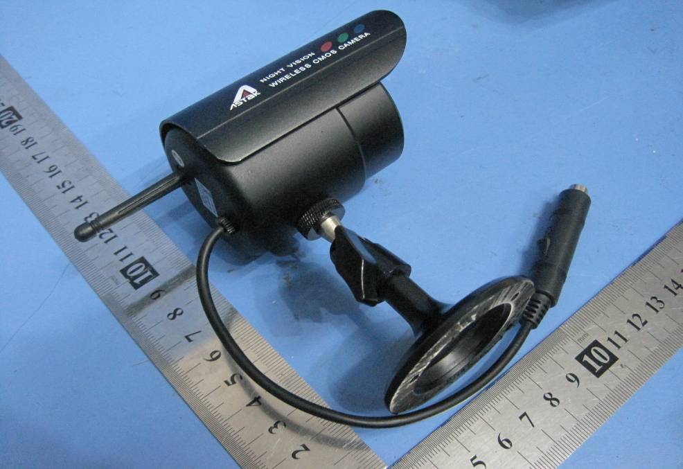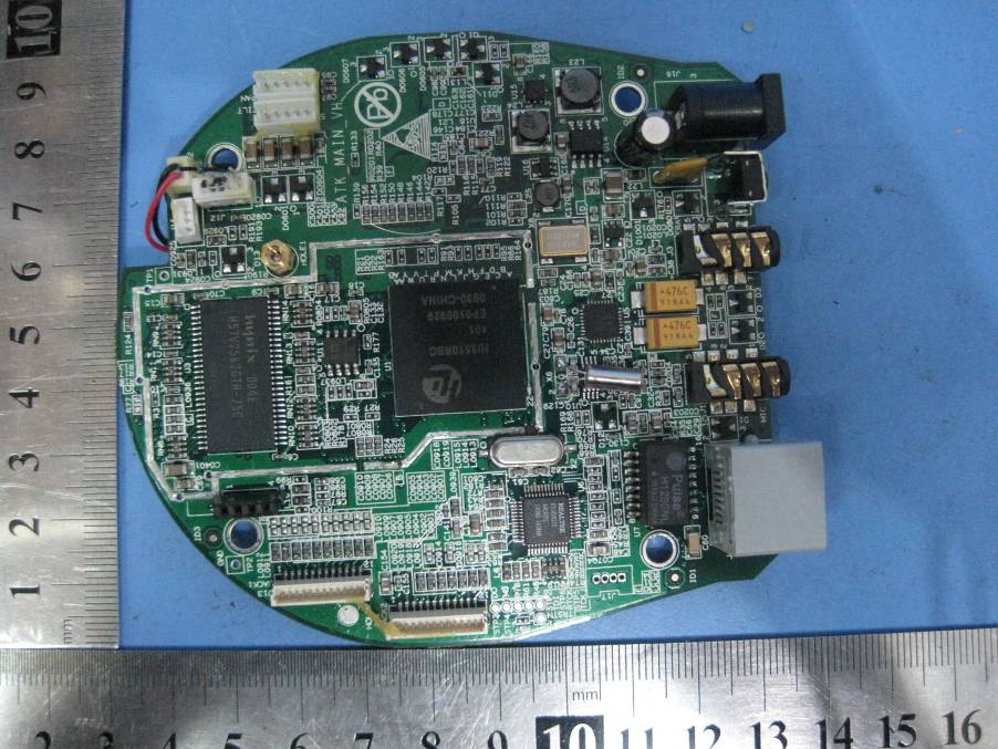
Text extracted from the exhibit documents filed with the FCC. Open a document above to read the original.
Note: The antenna(s) used for this transmitter must be installed to provide a separation distance of at least 20 cm from all persons and must not be co-located or operating in conjunction with any other antenna or transmitter. FCC NOTE: This device complies with Part 15 of the FCC Rules. Operation is subject to the following two conditions:(1)this device may not cause harmful interference, and (2) this device must accept any interference received, including interference that may cause undesired operation. The manufacturer is not responsible for any radio or TV interference caused by unauthorized modifications to this equipment. Such modifications could void the user's authority to operate the equipment. IC NOTE: Operation is subject to the following two conditions:(1) this device may not cause interference, and (2) this device must accept any interference, including interference that may cause undesired operation of the device. 11 For a Class B digital device or peripheral, the instructions furnished the user shall include the following or similar statement, placed in a prominent location in the text of the manual: Note: This equipment has been tested and found to comply with the limits for a Class B digital device, pursuant to part 15 of the FCC Rules. These limits are designed to provide reasonable protection against harmful interference in a residential installation. This equipment generates, uses and can radiate radio frequency energy and, if not installed and used in accordance with the instructions, may cause harmful interference to radio communications. However, there is no guarantee that interference will not occur in a particular installation. If this equipment does cause harmful interference to radio or television reception, which can be determined by turning the equipment off and on, the user is encouraged to try to correct the interference by one or more of the following measures: -- Reorient or relocate the receiving antenna. -- Increase the separation between the equipment and receiver. -- Connect the equipment into an outlet on a circuit different from that to which the receiver is connected. -- Consult the dealer or an experienced radio/TV technician for help.
5 5 4 4 3 3 2 2 1 1 DD CC BB AA Title SizeDocument NumberRev Date:Sheetof <Doc>VH <Title> A2 111Monday, August 09, 2010 Title SizeDocument NumberRev Date:Sheetof <Doc>VH <Title> A2 111Monday, August 09, 2010 Title SizeDocument NumberRev Date:Sheetof <Doc>VH <Title> A2 111Monday, August 09, 2010 HI3510ATKCM_MAINSCH_VH Hi3510 SDRAMFLASH EBI MII RT8201CP RJ45 USB1 AU6332 SD GPIO ULN2803A MOTOR USB0 UART0 POWER JTAGADM706RAR GPIO VI I2S TLV320AIC31 CONNECTOR ANTENNA WIFI MODULE CONNE CTOR CONNE CTOR IR LED MODULE CMOS SENSOR MODULE CONNECTOR GPIO SWITCH MODULE SN74LVC04A PCS3P7303 PCF8563TS CLOCK RTC RST/WATCHDOG CLOCK CLOCK USB_CLOCK 5V,3.3V,1.25V X9 27MHz X9 27MHz X425MHzX425MHz X512MHzX512MHz X1148MHzX1148MHz 12 34 X6 32.768K X6 32.768K
Astak, Inc. FCC ID: W8M-MOLE POWER OF ATTORNEY Aug. 17,2010 Federal Communications Commission Authorization and Evaluation Division 7435 Oakland Mills Road Columbia, MD 21046 To Whom It May Concern: We, the undersigned, hereby authorize Waltek Services (ShenZhen) Co., Ltd. (Philo Zhong) on our behalf, to apply to the Federal Communications Commission on our equipment. Any and all acts carried out by Waltek Services (ShenZhen) Co., Ltd. (Philo Zhong) on our behalf shall have the same effect as acts of our own. This authorization expires on Aug 18, 2011. This is to advise that we are in full compliance with the Anti-Drug Abuse Act. We, Astak, Inc., are not subject to a denial of federal benefits pursuant to Section 5301 of the Anti-Drug Act of 1988, 21 USC853a, and no party to the application is subject to a denial of federal benefits pursuant to that section. Sincerely, Astak, Inc. -------------------------------
Astak, Inc. Ref No.: WT10041451-S-E-F FCC ID Label This device complies with Part 15 of the FCC Rules. Operation is subject to the following two conditions:(1)this device may not cause harmful interference, and (2) this device must accept any interference received, including interference that may cause undesired operation. The Label must not be a stick-on paper. The Label on these products must be permanently affixed to the product and readily visible at the time of purchase and must last the expected lifetime of the equipment not be readily detachable. Proposed Label Location on EUT EUT Top View/ proposed FCC Label Location FCC ID: W8M-MOLE This device com plies with Part 15 of the FCC Rules. Operation is subject to the following two conditions:(1)this device ma y not cause harmful interference,and (2) this device must accept any interference received, including interference that may cause undesired operation.
FCC ID Label Sample for Model : CM-MOLE FCC ID : W8M-MOLE This device complies with Part 15 of the FCC Rules. Operation is subject to the following two conditions:(1)this device may not cause harmful interference, and (2) this device must accept any interference received, including interference that may cause undesired operation.
2.1 PCB 1 -Front View 2.2 PCB 1 - Back View 2.3 PCB 2 -Front View 2.4 PCB 2-Back View
operating description Connected with adapter of DC 12V. U14,U15 and U16 of will produce 5V,3.3V and 1.25V system voltage respectively. Then U15 and U16 will supply U1 (CPU) with power. X7 (27MHZ) start to work..The 7Pin of U11 gave a low level signel to Reset to system ,after 0.5s gave a high level signel.Then U1 read boot program from U4 (Nor Flash) to U2 and U3.After that U1 will run in U2 and U3 (SDRAM). Thus the entire system can run now. The module of WIFI is connected to J7, which is provided with system 3.3V voltage. U1 works and controls the WIFI module via USB1.1 data bus. Then WIFI module will work in 2.4GH ISM frequency band and can connect the network via Wireless Router. U8 is the SD Card controller, which is supplied with 5.0V controled by SD Card. When SD Card plug in, then 5.0V power On, and X3 (12MHZ) starts to run and provide U8 with clock signal. U8 works and controled by the U1 via USB data bus. And then USB HOST and SD card slot start to work..U6 is the ethernet controller, which is supplied with system 3.3V. When power on, X2 (25MHZ) starts to run and provide U6 with clock signal. U1 controls U6 via MII data bus.U7 translate U6 signel to Ethernet slot (J4), and then Ethernet start to work . U1 control the Motor, U9 translator U1 signel to Motor signel. U1 can control the Motor to turn up/down/left/right.Video signel came from CMOS Sensor Module. CMOS Sensor Module powered by system 3.3V .U1 controls Module via I2C data bus and video data come form ITU656 data bus.