W99PI01Remote Control
Creative Werks Incorporated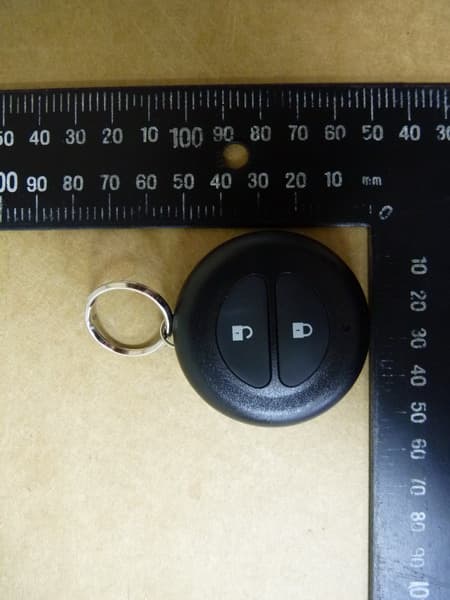
Click to zoom
Application Details
- Equipment Class
- DSC - Part 15 Security/Remote Control Transmitter
- Date of Grant
- Oct 25, 2013
- Application Purpose
- Original Equipment
- Date of Application
- Oct 25, 2013
- Equipment Note
- Remote Control
- Frequency Range
- 433.92000000 - 433.92000000
- Company
- Creative Werks Incorporated
- Country
- United States
Documents & Files
Document Text
Text extracted from the exhibit documents filed with the FCC. Open a document above to read the original.
Users Manual
1 2014 Rider’s Manual Indian Chief ® Classic Indian Chief ® Vintage Indian Chieftain™ 2 Copyright© 2013 Indian Motorcycle Company All information contained within this publication is based on the latest product information available at the time of publication. Product improvements or other changes may result in differences between this manual and the motorcycle. Depictions and/or procedures in this publication are intended for reference use only. No liability can be accepted for omissions or inaccuracies. Indian Motorcycle Company reserves the right to make changes at any time, without notice and without incurring obligation to make the same or similar changes to motorcycles previously built. Any reprinting or reuse of the depictions and/or procedures contained within, whether whole or in part, is expressly prohibited. INDIAN®, INDIAN MOTORCYCLE® and CHIEF® are registered trademarks of Indian Motorcycle Company. CHIEFTAIN™ is a trademark of Indian Motorcycle Company. iPhone®, iPod®, iPod nano®, and iPod touch® are trademarks of Apple Inc., registered in the U.S. and other countries. The Bluetooth® word mark and logos are registered trademarks owned by Bluetooth SIG, Inc. and any use of such marks by INDIAN MOTORCYCLE is under license. Other trademarks and trade names are those of their respective owners. Pandora ® is a registered trademark of Pandora Media, Inc. Garmin® and zumo® are registered trademarks of Garmin Ltd. or its subsidiaries. JCASE® is a registered trademark of Littelfuse, Inc. Printed in U.S.A. P/N 9924533 3 Table of Contents Introduction . . . . . . . . . . . . . . . . . . . . . . . . . 4 Safety . . . . . . . . . . . . . . . . . . . . . . . . . . . . . . 5 Reporting Safety Defects . . . . . . . . . . . . 16 Component Identification . . . . . . . . . . . . 18 Instruments, Features & Controls. . . . . . . 22 Pre-Ride Inspections. . . . . . . . . . . . . . . . . 57 Operation . . . . . . . . . . . . . . . . . . . . . . . . . 67 Maintenance . . . . . . . . . . . . . . . . . . . . . . . 79 Cleaning and Storage . . . . . . . . . . . . . . . 120 Specifications . . . . . . . . . . . . . . . . . . . . . 124 Warranty . . . . . . . . . . . . . . . . . . . . . . . . . 130 Maintenance Log. . . . . . . . . . . . . . . . . . . 141 Audio System (CHIEFTAIN) . . . . . . . . . . 143 Index . . . . . . . . . . . . . . . . . . . . . . . . . . . . 173 4 Introduction Congratulations on your purchase of a new INDIAN motorcycle. You have joined an elite family of motorcycle riders who have acquired a celebrated piece of American history by choosing to own an INDIAN motorcycle. Your new motorcycle is the end result of true dedication and craftsmanship by our engineering, design and assembly teams. It was designed and manufactured to meet our goal of providing you with a high quality motorcycle that you can ride trouble-free for many years to come. We hope you will take as much pride in riding your new motorcycle as our team did in building it for you. We urge you to read this rider’s manual thoroughly. It contains information essential to safe riding and proper maintenance of your motorcycle. Your authorized INDIAN MOTORCYCLE dealer knows your motorcycle best and should be consulted for service and assistance. Skilled technicians using advanced equipment and methods are best qualified to perform all major repairs and service your motorcycle may require. INDIAN motorcycles comply with all federal, state and local safety and emission regulations for the area of intended sale. Service and Warranty Information Some procedures are beyond the scope of this manual. See your dealer to purchase an INDIAN MOTORCYCLE Service Manual. Some procedures provided in the service manual require specialized knowledge, equipment, and training. Be sure you have the required technical skills and tools that are needed before you attempt ANY service on your motorcycle. Please contact your authorized dealer before attempting any service work that is beyond your level of technical knowledge or experience, or if the work requires specialized equipment. Operating Your Motorcycle Outside the U.S.A. If you plan to operate your motorcycle in countries other than the USA and Canada: • Service facilities or replacement parts may not be readily available. • Unleaded gasoline may not be available. The use of leaded fuels will cause engine damage, damage to your emissions systems and voiding of your warranty. • Gasoline may have a considerably lower octane rating. Improper fuel can cause engine damage. 5 Safety About the Rider's Manual Failure to follow all recommended precautions and procedures could result in severe injury or death. Always heed all safety precautions and follow all operation, inspection and maintenance procedures outlined in this manual. All references to RIGHT, LEFT, FRONT or REAR are from the operator’s perspective when seated in a normal riding position. If you have questions about the operation or maintenance of your motorcycle after you've read this manual, please see your authorized dealer. To locate the nearest authorized INDIAN MOTORCYCLE dealer, visit the INDIAN MOTORCYCLE web site at www.indianmotorcycle.com. Carefully read and understand the information found in the Safety section beginning on this page. To keep your motorcycle in peak condition on the road or in storage, understand and follow the procedures outlined in the Maintenance section beginning on page 79. Bring the manual along when you ride. Following the precautions and procedures in the manual will add to your enjoyment and help keep you safe. If you lose or damage this manual, please purchase a new one through any authorized INDIAN MOTORCYCLE dealer. This rider’s manual should be considered part of the motorcycle and should remain with the motorcycle when ownership changes. Safety Symbols and Signal Words The following signal words and symbols appear throughout this manual. Your safety and the safety of others is involved when these words an…
Text truncated - open the document above for the full version.
Users Manual
23 Instruments, Features and Controls Switches Power Switch Auxiliary Light Switch Saddlebag Lock Switch CHIEFCHIEFTAIN Power Switch Auxiliary Light Switch 24 Instruments, Features and Controls Switches SymbolSwitchDescription Emergency Flasher Switch (Hazard Switch) The hazard switch activates and cancels the emergency flashers. See page 25. High/Low Headlight Beam Switch The high/low headlight beam switch toggles the headlight between high beam and low beam. See page 27. Auxiliary Light Switch Press the auxiliary light switch to turn the auxiliary lights off or on. See page 27. Horn SwitchTo sound the horn, press the horn switch. Turn Signal SwitchMove the switch to the left to activate the left turn signals. Move the switch to the right to activate the right turn signals. A signal will deactivate automatically when speed or distance reach predetermined levels. To cancel a signal manually, move the switch to the center position and push it inward. Momentary Feature: Move the turn signal switch left or right and hold it in that position for at least one second. The momentary feature will activate and the signal will then cancel when the switch is released. Stop/Run SwitchPress the bottom of the switch (RUN) to allow the engine to start and run. Press the top of the switch (STOP) to stop the engine. See page 25. Starter SwitchUse the starter switch to start the engine. The engine stop/run switch must be in the RUN position. See page 26. Power SwitchThe power switch is located above the instrument gauge. Press and release the power switch to enable or disable all electrical power to the vehicle. See page 25. Saddlebag Lock Switch Press the lock switch to lock or unlock the saddlebags. The key fob can also be used to lock or unlock the saddlebags. 25 Instruments, Features and Controls Switches Power Switch The power switch is attached to the fuel tanks on the center console. Press and release the power switch to enable or disable all electrical power to the vehicle. The power switch does not have to be on to start the engine. See page 26. To disable all electrical power if the motorcycle is moving and the engine is running, press and hold the power switch for more than three (3) seconds. Tip:To save battery power, the vehicle will power off after five minutes of inactivity. Hazard Switch The power switch must be ON to activate the flashers, but once activated, the flashers will continue to flash when the power switch is turned off. When the flashers are active, all four turn signals flash. • Press the switch to activate the flashers. • Press the switch again to cancel the flashers. Engine Stop/Run Switch Use the engine stop/run switch to turn the engine off quickly. • Press the top of the switch (STOP) to interrupt the circuits and stop the engine. The engine should not start or run when the switch is in the STOP position. • Press the bottom of the switch (RUN) to complete the circuits and allow the engine to start and run. Tip:The headlights and any accessories plugged into power ports will remain on until the power switch is turned off. Audio System Switches See page 143 for audio systems operation. Cruise Control Switches Refer to the Cruise Control section of this manual (beginning on page 76) for cruise control operation. Run Stop 26 Instruments, Features and Controls Switches Engine Starter Switch Read the engine starting procedures before starting the engine. See page 70. The power switch does not have to be on to start the engine. Press and hold the starter switch to engage the one-touch starting feature, which activates the electrical system and starts the engine. The engine stop/run switch must be in the RUN position and the transmission must be in neutral. Keyless Ignition When the electrical system is activated with either the power switch or the starter switch, the key fob must be within range. If the key fob is not detected, the security light and/or power switch will flash. The electrical system will automatically shut down. The starter motor will not engage during this time. If a key fob is not available, your personal identification number (PIN) can be entered using the turn signal switches to unlock the security system. See page 114. Saddlebag Lock Switch If your model is equipped with electric saddlebag locks, the locks can be controlled by either the key fob or the lock switch on the console. When using the console lock switch, the key fob must be within range. If the key fob is not detected, the security light and/or power switch will flash. The system will not perform the lock or unlock command. Starter Switch Saddlebag Lock Switch Key Fob Lock Unlock 27 Instruments, Features and Controls Switches Ignition/Light Switch The headlights automatically come on when the engine is started. WARNING!Motorcycle riders must remain as visible as possible at all times. To aid in this, the headlight must be on at all times. Do not modify the ignition/light switch wiring to circumvent the automatic headlight feature. To gg l e S w i t c h e s All models are equipped with toggle switches on the front side of the left and right handlebar controls. The LEFT- TOGGLE switch is active for all models. The RIGHT-TOGGLE switch is active only for CHIEFTAIN models. The power switch must be ON. Use the switches to toggle through the modes of the multi-function display and to change settings in the display. High/Low Headlight Beam Switch The high/low headlight beam switch toggles the headlight between high beam and low beam. To activate the high beam, press the upper portion of the switch. To activate the low beam, press the lower portion of the switch. The headlights operate only when the engine is running. You can use the high/low headlight beam switch to override this function and allow the headlights to operate when the engine is not running. Turn the power switch on, then toggle the high/low headlight beam switch to turn the headlights on. Auxiliary Light Switch The auxiliary lights provide…
Text truncated - open the document above for the full version.
Users Manual
31 Instruments, Features and Controls Instrument Cluster (CHIEF) Multi-Function Display (MFD) Diagnostic Functionality Certain conditions will cause an error message to display in the screen. If this occurs, please see your authorized dealer. Engine Error Codes The error screen displays only when the CHECK ENGINE light is on or when it goes on and off during one ignition cycle. Error codes display only during the current ignition cycle. When the power switch is turned OFF, the code and message is lost, but will reappear if the fault reoccurs after restarting the engine. If the CHECK ENGINE indicator lamp illuminates, retrieve the error codes from the display. 1. If the error codes are not displayed, use the LEFT-TOGGLE switch to toggle until “Ck ENG” displays on the main line of the display. 2. Press and hold the LEFT-TOGGLE switch to enter the diagnostics code menu. 3. Record the three numbers displayed in the gear position, clock and odometer displays. 4. See an authorized dealer for code details and diagnosis. MessageLocationIndicates LODC Voltage ScreenVoltage remains below 11.0 volts for more than 10 seconds OVDC Voltage ScreenVoltage remains above 15.0 volts for more than 10 seconds ERRORAllChecksum error (gauge malfunction) Suspect Parameter Number (SPN) Error Code Number (0-9) Failure Mode Indicator (FMI) 32 Instruments, Features and Controls Instrument Cluster (CHIEF) Multi-Function Display (MFD) Low Oil Pressure Display “LO OIL” displays under the following conditions. ConditionIndicatesAction Required Engine oil pressure has dropped while the engine is running. Oil pressure is below a safe operating pressure. Stop the engine as soon as safely possible and check the oil level. If the oil level is sufficient, but “LO OIL” continues to display after restarting the engine, stop the engine immediately. 33 Instruments, Features and Controls Instrument Cluster (CHIEFTAIN) The instrument cluster includes the speedometer, tachometer, fuel gauge, indicator lamps and multi-function display (MFD). Speedometer The speedometer displays forward vehicle speed in either miles per hour or kilometers per hour. Tachometer The tachometer displays engine speed in revolutions per minute (RPM). A red line on the face of the gauge indicates the maximum safe engine speed. Excessive engine speed can cause engine damage or failure, which could result in serious injury or death. Do not allow engine speed to exceed the red line. Fuel Gauge The fuel gauge displays fuel level. For the most accurate reading, sit on the motorcycle and bring it to the upright position. Speedometer Indicator Lamps Multi-Function Display Tachometer Fuel Gauge 34 Instruments, Features and Controls Instrument Cluster (CHIEFTAIN) Indicator Lamps LampIndicatesCondition NeutralThe transmission is in neutral and the power switch is ON. Vehicle Speed When standard mode is selected, speed displays in miles per hour. When metric mode is selected, speed displays in kilometers per hour. High BeamThe headlight switch is set to high beam. This indicator will flash if there is a problem with the low or high beam light. Low Oil Pressure This lamp illuminates when oil pressure drops below a safe operating pressure while the engine is running. If this lamp illuminates while the engine is running above idle speed, turn the engine off as soon as safely possible and check the oil level. If the oil level is correct and the lamp remains on after the engine is restarted, turn the engine off immediately. See your dealer. Low FuelThis lamp illuminates when approximately one gallon (3.8 liters) of fuel remains in the fuel tank. The LCD Display will switch into a Low Fuel Mileage Counter Mode to provide the rider with mileage tracking from the time the indicator was activated. Turn SignalOne arrow flashes when the corresponding turn signal is activated. Both arrows flash when the hazard signal is activated. If there is a problem in the signal system, the lamps will flash at twice the normal rate. 35 Instruments, Features and Controls Instrument Cluster (CHIEFTAIN) Indicator Lamps LampIndicatesCondition Low Battery Vo l t a g e This lamp illuminates when battery voltage is low. Turn non-essential accessories off to conserve power. Make sure the charging system is operating properly. See page 119. This lamp also illuminates with the security light and/or power switch when the key fob battery is low, and with the TPMS lamp when the TPMS sensor battery is low. Cruise Control Status Amber Lamp: Cruise control is enabled, but not set. Green Lamp: Cruise control is set to the desired speed. Read the safety and operation procedures before using cruise control. See page 76. ABS Not Activated The indicator remains on until the anti-lock system activates, which occurs when vehicle speed exceeds 6 MPH (10 km/h). When the lamp is illuminated, the anti-lock brakes will not activate, but the conventional brake system will continue to operate normally. Check EngineThis lamp illuminates briefly when the power switch is turned ON. This indicates proper function. If this lamp illuminates while the engine is running, see an authorized dealer promptly. The light will remain on if the tilt sensor shuts down the engine. If abnormal sensor or engine operation is detected the light will remain on as long as the fault condition exists. Retrieve the error codes for diagnosis. See page 40. Tire Pressure Monitoring System (TPMS) The TPMS indicator illuminates if low tire pressure is detected. It will also illuminate along with the Low Battery Voltage indicator when TPMS battery power is low, requiring service. Security System Locked This indicator lamp illuminates while the security system is searching for the key fob signal and when the security system is locked. The lamp flashes if the key fob is not detected within range or if the fob is not programmed properly. It also illuminates with the low battery voltage indicator when the key fob battery is low. 36 Instruments, Features and …
Text truncated - open the document above for the full version.
Users Manual
71 Operation Starting the Engine 9. Leave the throttle closed and allow the engine to idle. Idle speed will gradually slow to normal as the engine warms to operating temperature. Tip:Do not rev the engine or put the transmission in gear immediately after starting the engine. Allow the engine to idle for about 30 seconds after a warm start or at least one minute after a cold start (longer in cold weather). This will allow oil to reach all areas before the engine is put under load. NOTICE:Do not run the engine at high RPM with the clutch disengaged or the transmission in neutral. Maximum safe engine speed is 5400 RPM. Never exceed the maximum safe RPM as this could result in serious engine damage. NOTICE:The engine is air-cooled and requires unrestricted air flow to ensure proper operating temperature. Long periods of idling or traveling at very low speeds (such as during a parade) may overheat the engine, resulting in serious engine damage. 72 Operation Shifting Gears WARNING!Forced shifting (with clutch engaged) could cause damage to the engine, transmission and drive train. Such damage could cause loss of control, which could result in serious injury or death. Always pull the clutch lever fully toward the handlebars to disengage the clutch before shifting gears. This motorcycle is equipped with a six-speed transmission. Neutral is located between first and second gear. Press downward on the toe lever to shift to a lower gear. Lift upward on the toe lever to shift to a higher gear. Release the clutch lever after each gear shift. Shifting to neutral is easiest if the motorcycle is rolling slowly. To shift from first gear to neutral, gently lift the toe lever a half stroke. Tip:The transmission is in neutral if you can move the motorcycle forward or rearward freely without disengaging the clutch. If the power switch is ON, the neutral indicator illuminates when the transmission is in neutral. Shifting Gears While Stationary To locate neutral when the motorcycle is stationary, use one of the following techniques to load and unload the transmission shift dogs, which allows them to disengage: 1. With the clutch disengaged (lever pulled inward), shift into neutral while rocking the motorcycle forward and rearward. 2. With the transmission in first gear, gently release the clutch until it just begins to engage. Apply upward pressure on the toe lever and quickly pull the clutch inward. To shift gears when the motorcycle is stationary (engine may be running or stopped), disengage the clutch and apply slight pressure on the shift lever while rocking the motorcycle forward and rearward. 1 3 2 4 5 6 N 73 Operation Shifting Gears Shifting Gears While Driving 1. Start the engine. See page 70. 2. With the engine at idle speed, apply the front brakes. 3. Disengage the clutch (pull the clutch lever fully toward the handlebar). 4. Push the toe lever downward until you feel it stop in first gear. 5. Release the brake lever. 6. Simultaneously release the clutch lever while opening the throttle (rolling the throttle control grip rearward) in one smooth motion. As the clutch begins to engage, the motorcycle will move forward. 7. To shift to a higher gear, accelerate smoothly to the recommended shift point. See Recommended Shift Points chart. With a quick motion, simultaneously close the throttle completely and disengage the clutch. Raise the toe shift lever until you feel it stop at the next gear. Simultaneously release the clutch lever and open the throttle in one smooth motion. Tip:Within the recommended speed ranges (see Recommended Shift Points chart), you can downshift to slow the motorcycle or to increase power. You may want to downshift when climbing a hill or passing. Downshifting also helps to decrease speed when combined with closing the throttle. 8. To shift to a lower gear (downshift), simultaneously pull the clutch lever toward the handlebar and close the throttle. Move the toe shift lever downward until you feel it stop at the next gear. Simultaneously release the clutch lever while opening the throttle. WARNING!Downshifting improperly could cause transmission damage, loss of traction and loss of control, which could result in serious injury or death. • Reduce speed before downshifting. Always downshift within the recommended shift points. • Use extreme caution when downshifting on wet, slippery or other low traction surfaces. Release the clutch lever very gradually in these conditions. • Avoid downshifting in a curve. Downshift before entering the curve. 74 Operation Shifting Gears Recommended Shift Points Upshifting (Accelerating)Downshifting (Decelerating) Gear ChangeRecommended SpeedGear ChangeRecommended Speed 1 to 215 MPH (24 km/h)6 to 540 MPH (64 km/h) 2 to 325 MPH (40 km/h)5 to 435 MPH (56 km/h) 3 to 435 MPH (56 km/h)4 to 325 MPH (40 km/h) 4 to 545 MPH (72 km/h)3 to 215 MPH (24 km/h) 5 to 650 MPH (80 km/h)2 to 110 MPH (16 km/h) 75 Operation Braking Always allow sufficient stopping distance so that brakes can be applied gradually. Tip:Applying slightly more front brake than rear brake generally provides the best braking performance. 1. To slow the motorcycle with the brakes, close the throttle and apply the front and rear brakes evenly and gradually. Tip:When the anti-lock brakes engage during a braking event, the rider will feel pulsing at the brake levers. Continue to apply steady pressure to the brakes for the best stopping performance. 2. As the motorcycle slows, disengage the clutch, or downshift each time vehicle speed reaches a downshift point. WARNING!Braking improperly could result in loss of control, which could result in serious injury or death. Avoid braking abruptly. Always apply the brakes gradually, especially on wet, slippery or other low traction surfaces. Avoid braking in a curve or turn. Bring the motorcycle to the upright position before applying the brakes. Accelerating Accelerate by opening the throttle (rolling the throttle control grip rearward). For even accelerat…
Text truncated - open the document above for the full version.
Users Manual
126 Specifications Model Year 2014CHIEF / CHIEFTAIN Drive System Primary DriveGear Drive Wet Clutch Crank Gear55 Teeth Clutch Gear86 Teeth Clutch TypeWet, Multi-Plate Primary Reduction Ratio1.564:1 Transmission Type6 Speed/Constant Mesh/Foot Shift 1st Gear Ratio2.733:1 2nd Gear Ratio1.864:1 3rd Gear Ratio1.385:1 4th Gear Ratio1.103:1 5th Gear Ratio0.943:1 6th Gear Ratio0.811:1 Gear Shift Pattern1 Down/5 Up Final Drive TypeBelt Drive, 152-Tooth Transmission30-Tooth Rear Wheel66-Tooth Ratio2.2:1 Overall Gear Ratio 1st Gear9.403:1 2nd Gear6.411:1 3rd Gear4.763:1 4th Gear3.796:1 5th Gear3.243:1 6th Gear2.789:1 127 Specifications Model Year 2014CHIEFCHIEFTAIN Wheels And Tires Front Wheel Size/Type3.5 in. x 16 in. 40 Spoke3.5 in. x 16 in. Cast Aluminum Rear Wheel Size/Type5 in. x 16 in. 40 Spoke5 in. x 16 in. Cast Aluminum Front Tire Type/SizeWhite 130/90-B16 67H American EliteBlack 130/90-B16 73H Dunlop Elite 3 Rear Tire Type/SizeWhite 180/65-B16 81H American EliteBlack 180/60-R16 80H Dunlop Elite 3 Electrical Alternator710W @ 2000 RPM Battery12 volt, 20 amp/hour, 330 CCA (cold cranking amps) Sealed Glass Mat Power PointsFront - 10 amp maximum Rear - 10 amp maximum (Combined - 10 amp maximum) Voltage Regulator14.4 volts/42 amp Lamps (all bulbs are 12 volt) HeadlightH4 12V 60/55W LL Auxiliary LightH8 35W (35W) Tail/Brake LightNon-serviceable LED Turn SignalNon-serviceable LED License PlateNon-Serviceable LED Front Fender LightNon-Serviceable LED SpeedometerNon-Serviceable LED Indicator LightsNon-Serviceable LED 128 Specifications Fuel Recommendation For best performance, use only unleaded gasoline with a 91 pump octane minimum (R+M/2 Method). DO NOT USE E-85 GASOLINE OR GASOLINE CONTAINING METHANOL. Using E85 or gasoline/methanol blends can result in poor starting and driveability, engine damage and damage to critical fuel system components. • Gasoline containing up to 15% Ethanol can be used. • Gasoline containing up to 15% Methyl Tertiary Butyl Ether (MTBE) can be used. In the event that the recommended premium unleaded gasoline is not available and low octane fuel must be used, fill the fuel tank only partially with unleaded regular gasoline, then fill the tank fully with premium unleaded gasoline as soon as possible. Engine Oil Recommendation We recommend the use of INDIAN MOTORYCLE Premium Synthetic Blend 20W-40 Engine Oil for your motorcycle. This oil is formulated with synthetic-based oil and premium engine additive which have physical properties that meet API SM and ILSAC GF-4 specifications. Do not blend oil additives with engine oil. If oil must be added in an emergency and the recommended oil is not available, choose only a high-quality 20W-40 motorcycle oil. Change back to the recommended oil at the first opportunity. NOTICE:Use of non-recommended lubricants can result in engine damage. Damage resulting from the use of non- recommended lubricants is not covered by warranty. Fo r k O i l We recommend the use of INDIAN MOTORCYCLE Fork Oil for your motorcycle. Brake Fluid We recommend the use of INDIAN MOTORCYCLE DOT 4 Brake Fluid for both brake master cylinders. DO NOT use DOT 5 silicone fluid. 129 Specifications Identification Number Record Record important identification numbers below. Vehicle Identification Number (VIN) (see page 17) Engine Identification Number (see page 20) 130 Warranty INDIAN MOTORCYCLE Warranty Policy LIMITED WARRANTY Indian Motorcycle Company, 2100 Highway 55, Medina, MN 55340 (INDIAN MOTORCYCLE) gives a ONE YEAR LIMITED WARRANTY on all components of your INDIAN motorcycle against defects in material or workmanship. This warranty covers parts and labor charges for repair or replacement of defective parts and begins on the date of purchase by the original retail purchaser. This warranty is transferable to another owner during the warranty period through an INDIAN MOTORCYCLE dealer, but any such transfer will not extend the original term of the warranty. The duration of this warranty may vary by international region based upon local laws and regulations. EXTENDED SERVICE CONTRACT (ESC) NOT PART OF LIMITED WARRANTY INDIAN MOTORCYCLE provides the original retail purchaser of this INDIAN motorcycle with a 5 year extended service contract (ESC) that begins at the time of registration. The ESC is separate from, has different terms and coverage, is not a part of, and has no effect on the terms, coverage, or duration of this Limited Warranty. Please review those terms and conditions for information regarding the ESC. In some circumstances, the ESC may not be transferred to a used or second-hand purchaser of this INDIAN motorcycle. INDIAN MOTORCYCLE makes no representations and disclaims all liability regarding the availability or transferability of the ESC to a used or second-hand purchaser. REGISTRATION At the time of sale, the Warranty Registration Form must be completed by your dealer and submitted to INDIAN MOTORCYCLE within ten days of purchase. Upon receipt of this registration, INDIAN MOTORCYCLE will record the registration for warranty. No verification of registration will be sent to the purchaser as the copy of the Warranty Registration Form will be your proof of warranty coverage. If you have not signed the original registration and received the customer copy, please contact your dealer immediately. NO WARRANTY COVERAGE WILL BE ALLOWED UNLESS YOUR MOTORCYCLE IS REGISTERED WITH INDIAN MOTORCYCLE. Initial dealer preparation and set-up of your motorcycle is very important in ensuring trouble-free operation. Purchasing a vehicle in the crate or without proper dealer set-up will void your warranty coverage. 131 Warranty INDIAN MOTORCYCLE Warranty Policy WARRANTY COVERAGE AND EXCLUSIONS: LIMITATIONS OF WARRANTIES AND REMEDIES This INDIAN MOTORCYCLE limited warranty excludes any failures that are not caused by a defect in material or workmanship. THIS WARRANTY DOES NOT COVER CLAIMS OF DEFECTIVE DESIGN. This warranty also does not cover acts of God, accidental damag…
Text truncated - open the document above for the full version.
Contact Information
Applicant
Joel Fleming(Division Manager)
Technical Contact
Worldwide Testing Services (Taiwan) Co., Ltd.Tse-Ming Chang
[email protected]+886-2-6606-8877
6F., No. 58, Lane 188, Ruey Kuand Rd. · Taipei · Taiwan
Test Firm
Worldwide Testing Services (Taiwan) Co., Ltd.Rex Kao
Technical Specifications
| # | Rule Parts | Frequency Range | Power Output |
|---|---|---|---|
| 1 | 15.231 | 433.92 MHz - 433.92 MHz | - |
Other Applications from Creative Werks Incorporated

W99-PKE9185-10
Jun 24, 2014Receiver
Equipment Class
DCD - Part 15 Low Power Transmitter Below 1705 kHz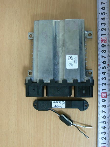
W99PI02
Oct 25, 2013Car machine
Equipment Class
DCD - Part 15 Low Power Transmitter Below 1705 kHz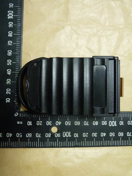
W99TI1
Jul 17, 2013Transmitter
Equipment Class
DSC - Part 15 Security/Remote Control Transmitter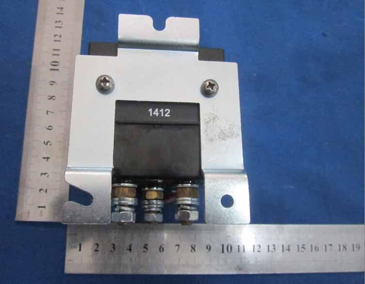
W99RL31
Jan 19, 2013Relay
Equipment Class
CYY - Communications Receiver used w/Pt 15 Transmitter