W9V-OAB48-GPLTE CPE
Green Packet Berhad, Taiwan
Click to zoom
Application Details
- Equipment Class
- JAB - Part 15 Class B Digital Device
- Date of Grant
- Feb 12, 2021
- Application Purpose
- Original Equipment
- Date of Application
- Feb 12, 2021
- Equipment Note
- LTE CPE
- Company
- Green Packet Berhad, Taiwan
- Country
- Taiwan
Documents & Files
Document Text
Text extracted from the exhibit documents filed with the FCC. Open a document above to read the original.
Users Manual
123 456 7 QUICK USER GUIDE LTE CPE OA-B48 About This Document This document serves as a brief overview and setup guide for OA series ODUs (Outdoor Units). The OA series is a LTE outdoor unit. In this document, the terms ODU, Outdoor CPE, and Outdoor Unit are used interchangeably. Ensure that you have everything required to properly set up your device. Included Hardware Version No. : V1.0 Release Time : 2020-12 Because of the product version upgrade or other reasons, the content of the document will not be updated on a regular basis. Unless otherwise agreed, this document is used only as a guide, all statements, information and advice in this document do not constitute any express or implied guarantee. Note: ODU UnitPoE Injector Cap x 2 Strap x 2 Rubber Pad x2 Ethernet Cable It is important to comply with the precautions listed below before installing. It must be installed by qualified service personnel who are well-trained in the correct procedures for installing the equipment. Avoid installing or working on equipment in adverse weather conditions. Do not disassemble the product. Warranty void if seal is broken. Please install the device underneath the eaves of house, or the eaves of equipment room on rooftop. Do not install the device on the lightning rod pole. A random lightning could easily cause fatal damage to the device. Ensure that the device is within the shielding angle of the lightning rod. Lightning I Lightning induction I EMD damage is NOT covered under warranty. Before Installing the ODU 1. 2. 3. 4. 5. 6. 7. 8. Step 1. Power off the ODU, Insert SIM card into the SIM slot located on the bottom panel. Step 2. Place the protective cap on the SIM slot after insertion. Step 3. Screw the protective cap firmly to protect the SIM slot against water and dust. SIM Card Installation Note: The ODU uses a Standard-size SIM card (Also called, Mini SIM or 2FF SIM card) Note: The Mounting Pole’s diameter should be 33-57mm. Note: LAN Cable’s diameter should be 5-10mm. Mounting kit : Header Installation : Installing Outdoor Unit Wiring Diagram Note: Make sure SIM is inserted correctly before powering up. Step 1 Connect the (CAT 5e) Outdoor Ethernet cable between ODU and the "Power + Data out" port on the PoE. Step 2 Connect the provided indoor Ethernet cable between the 'Data In' port on the POE and your PC or router. Wall PoE Injector PC Step 1 Step 2 For best signal level and connection quality, the ODU must be aimed directly at the servicing tower. Fine tuning the signal level can be done by making small, incremental adjustment up, down or side to side in order to improve signal, once established. The ODU signal strength level can be observed on the RF Indicator LED lights located on the bottom panel, as shown below. The more LEDS that are lit, the stronger the signal level. Adjusting For Optimal Installation WeakStrong RF LEDs S Y S S I M E T H R U N (ODU) LED Behavior When the ODU is powered on, the LEDs on the bottom panel will have the following behavior. State DescriptionLED BehaviorLED illustration LAN ConnectedThe ETH LED On S Y S S I M E T H R U N Signal Strength weak Signal strength is weak Signal Strength good Signal strength is good Signal Strength strong Signal strength is strongAll signal LEDs steady on LTE Scanning RF RF RF RF LAN Disconnected The ETH LED Off No SIM cardThe SIM LED Off SYS linkedThe SYS LED On SYS no linkThe SYS LED Off CPE OperationThe RUN LED Blinking SIM card normalThe SIM Card is readyThe SIM LED On SIM card abnormal The SIM LED Blinking RF Firmware Upgrading RF Signal Strength medium Signal Strength is medium The CPE is searching for a frequency channel or is performing network entry The CPE has a successful connection with a device on the LAN The CPE does not have an Ethernet connection with the LAN The SIM Card in abnormal state The SIM Card is Undetected The CPE attached to LTE network The CPE not attached to LTE network The CPE is operating properly The CPE is upgrading the firmware All signal LEDs scrolling blink one by one The first three signal LEDs steady on, the last one off The first two signal LEDs steady on, the last two off All signal LEDs blinking simultaneously Only first signal LED steady on, the other three off CE Regulations by turning the equipment off and on, the user is encouraged to try to correct the interference by one or more of the following measures: This equipment complies with radio frequency (RF) exposure limits adopted by the Federal Communications Commission for an uncontrolled environment. This equipment should be installed and operated with minimum distance 24 cm between the radiator & your body. FCC RF Exposure Compliance ■Reorient or relocate the receiving antenna. ■Increase the separation between the equipment and receiver. ■Connect the equipment into an outlet on a circuit different from that to which the receiver is connected. ■Consult the dealer or an experienced radio/TV technician for help. Claim FCC Regulations This device complies with part 15 of the FCC Rules. Operation is subject to the following two conditions: (1) This device may not cause harmful interference. and (2) this device must accept any interference received, including interference that may cause undesired operation. ■ This equipment has been tested and found to comply with the limits for a Class B digital device, pursuant to part 15 of the FCC Rules. These limits are designed to provide reasonable protection against harmful interference in a residential installation. This equipment generates, uses and can radiate radio frequency energy and, if not installed and used in accordance with the instructions. may cause harmful interference to radio communications. However, there is no guarantee that interference will not occur in a particular installation. if this equipment does cause harmful interference to radio or t elevision reception, which can b e determined ■ Changes or modifications not expressly approved by the party responsible for compliance …
Text truncated - open the document above for the full version.
External Photos
EXHIBIT B - EUT EXTERNAL PHOTOGRAPHS
Internal Photos
EXHIBIT C - EUT INTERNAL PHOTOGRAPHS Antenna
Test Report
FCC PART 15B TEST REPORT For Green Packet Berhad, Taiwan 2F, NO.23, LANE 583 RUEIGUANG RD, NEIHU DISTRICT, Taipei City,Taiwan FCC ID: W9V-OAB48-GP Report Type: Original Report Product Type: LTE CPE Test Engineer: Barry Yang, Asa Chen, Felix Wang Report Number: RDG201104005-00A Report Date: 2020-12-15 Reviewed By: Ivan Cao Assistant Manager Test Laboratory: Bay Area Compliance Laboratories Corp. (Dongguan) No.69 Pulongcun, Puxinhu Industry Area, Tangxia, Dongguan, Guangdong, China Tel: +86-769-86858888 Fax: +86-769-86858891 www.baclcorp.com.cn Bay Area Compliance Laboratories Corp. (Dongguan) Report No.: RDG201104005-00A Page 2 of 20 TABLE OF CONTENTS General Information ......................................................................................................................................................... 3 PRODUCT DESCRIPTION FOR EQUIPMENT UNDER TEST (EUT) ....................................................................................... 3 OBJECTIVE ....................................................................................................................................................................... 3 TEST METHODOLOGY ..................................................................................................................................................... 3 MEASUREMENT UNCERTAINTY ....................................................................................................................................... 3 TEST FACILITY ................................................................................................................................................................ 4 DECLARATIONS ............................................................................................................................................................... 4 System Test Configuration .............................................................................................................................................. 5 DESCRIPTION OF TEST CONFIGURATION ......................................................................................................................... 5 EQUIPMENT MODIFICATIONS .......................................................................................................................................... 5 EUT EXERCISE SOFTWARE ............................................................................................................................................. 5 SUPPORT EQUIPMENT LIST AND DETAILS ....................................................................................................................... 5 BLOCK DIAGRAM OF TEST SETUP ................................................................................................................................... 6 TEST EQUIPMENT LIST .................................................................................................................................................... 7 ENVIRONMENTAL CONDITIONS ....................................................................................................................................... 7 Summary of Test Results ................................................................................................................................................. 8 Conducted emissions......................................................................................................................................................... 9 EUT SETUP ..................................................................................................................................................................... 9 EMI TEST RECEIVER SETUP ............................................................................................................................................ 9 TEST PROCEDURE ............................................................................................................................................................ 9 CORRECTED AMPLITUDE & MARGIN CALCULATION ................................................................................................... 10 TEST DATA .................................................................................................................................................................... 11 Radiated emissions .......................................................................................................................................................... 13 EUT SETUP ................................................................................................................................................................... 13 EMI TEST RECEIVER SETUP .......................................................................................................................................... 14 TEST PROCEDURE .......................................................................................................................................................... 14 CORRECTED AMPLITUDE & MARGIN CALCULATION ................................................................................................... 14 TEST DATA .................................................................................................................................................................... 15 Bay Area Compliance Laboratories Corp. (Dongguan) Report No.: RDG201104005-00A Page 3 of 20 GENERAL INFORMATION Product Description for Equipment under Test (EUT) EUT Name: LTE CPE EUT Model: OA-B48 Adapter Information Model: G0720-240-100 Input: 100-240Vac 50/60Hz 0.75A MAX Output: 24Vdc 1A Rated Input Voltage: 24Vdc from Adapter Serial Number: RDG201104005-RF-S1 EUT Received Date: 2020.11.04 EUT Received Status: Good Objective This report is prepared on behalf of Green Packet Berhad, Taiwan in accordance with Part 2, Part J, and Part 15, Subpart A and B of the Federal Communications Commission’s rules. The objective is to determine the…
Text truncated - open the document above for the full version.
Test Setup Photos
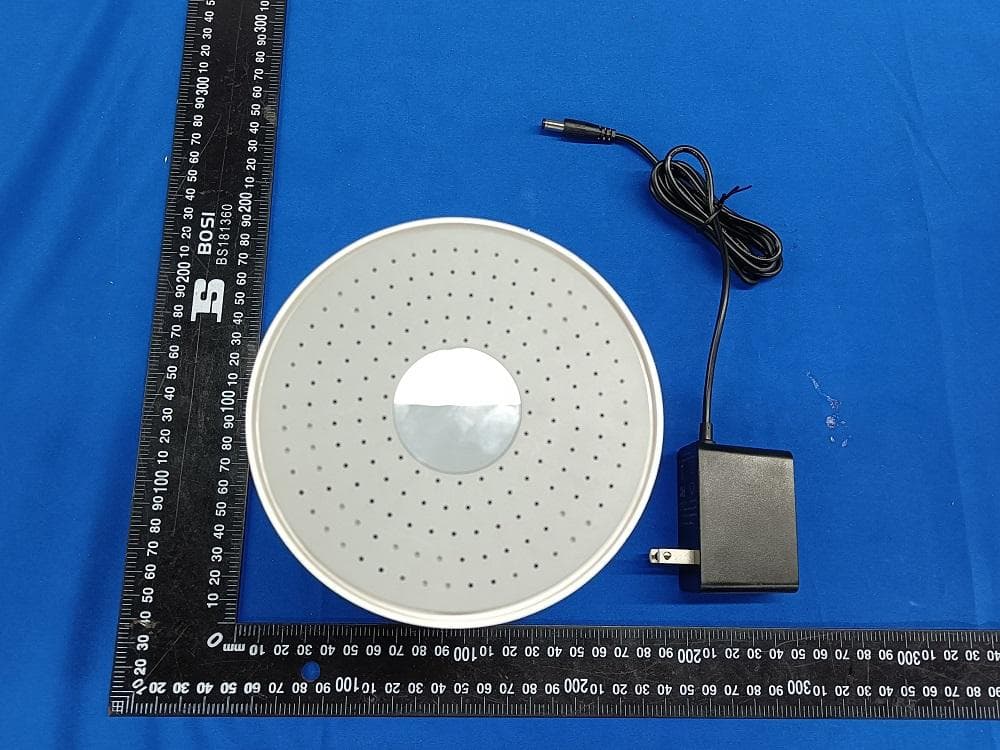
EXHIBIT B - TEST SETUP PHOTOGRAPHS CE front View M1 CE side View M1 RE below 1G front View RE below 1G rear View RE above 1G front View RE above 1G rear View
Contact Information
Applicant
Frank Hsu(VP)
Test Firm
Bay Area Compliance Laboratories Corp.(Dongguan)David Zhang
[email protected]0086 0769 86858888
Technical Specifications
| # | Rule Parts | Frequency Range | Power Output |
|---|---|---|---|
| 1 | 15B | - | - |
Other Applications from Green Packet Berhad, Taiwan
W9V-D2K-GP
May 18, 2021Multimode 4G LTE Cat.6 Indoor CPE
Equipment Class
DTS - Digital Transmission System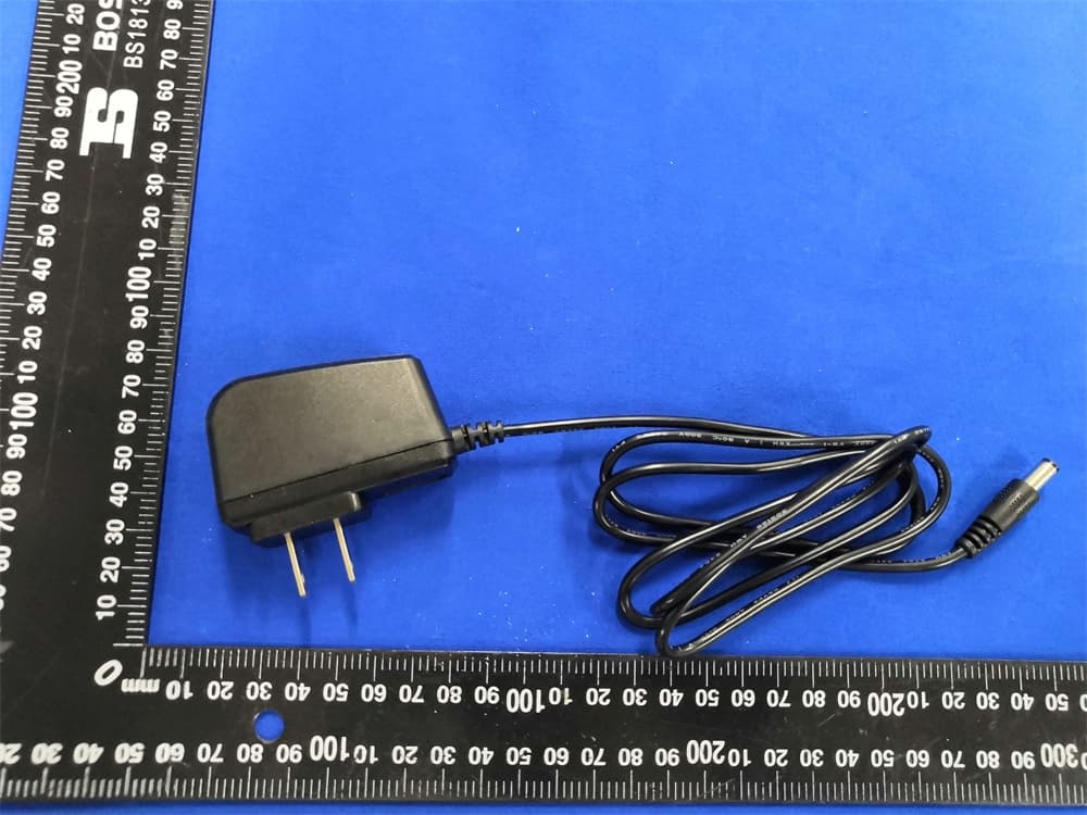
W9V-DA725-GP
Sep 21, 2020LTE CPE
Equipment Class
DTS - Digital Transmission System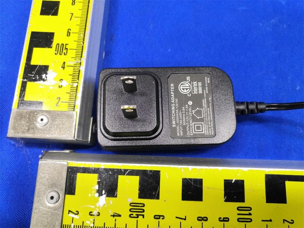
W9V-DS735-GP
Apr 07, 2020LTE CPE
Equipment Class
NII - Unlicensed National Information Infrastructure TX
W9V-OT350-GP
Sep 22, 2015LTE Outdoor CPE (Band 43)
Equipment Class
TNB - Licensed Non-Broadcast Station Transmitter
W9V-IF250-GP
Aug 25, 2014LiTE Band 7 Indoor CPE
Equipment Class
TNB - Licensed Non-Broadcast Station Transmitter