WA2ST210Quad band GSM/GPRS Vehicle Tracker
Suntech International Ltd.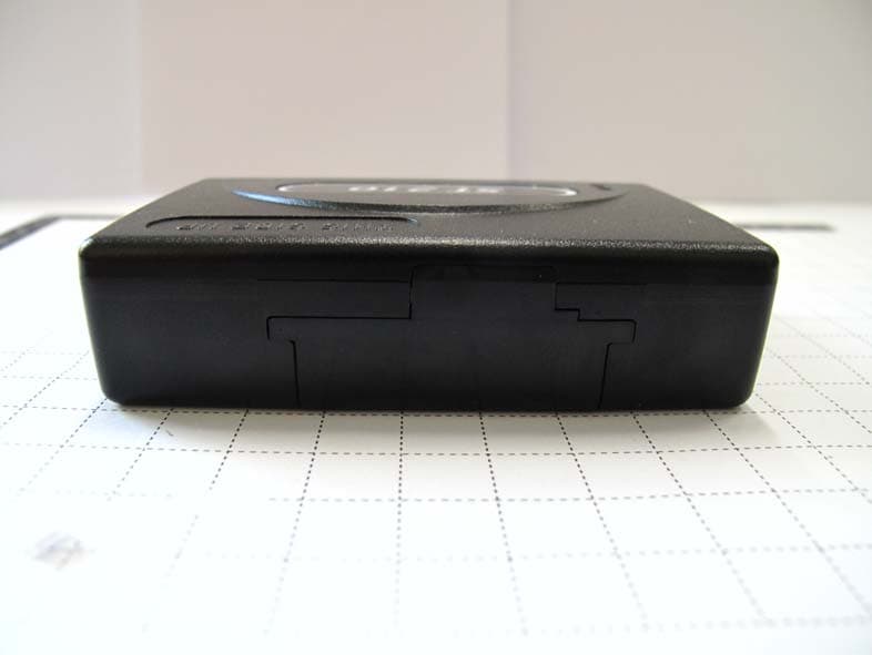
Click to zoom
Application Details
- Equipment Class
- PCB - PCS Licensed Transmitter
- Date of Grant
- Sep 08, 2010
- Application Purpose
- Original Equipment
- Date of Application
- Sep 08, 2010
- Equipment Note
- Quad band GSM/GPRS Vehicle Tracker
- Frequency Range
- 1850.20000000 - 1909.80000000
- Company
- Suntech International Ltd.
- Country
- South Korea
Documents & Files
Document Text
Text extracted from the exhibit documents filed with the FCC. Open a document above to read the original.
Users Manual
ST210 User Guide Suntech International Ltd. Table of Contents 1. Introduction ........................................................................................................................................... 1 2. Parameter Setting via SMS................................................................................................................... 1 For reporting GPS position, the device should be set with adjustable parameters before installation. ............................................................................................................................................. 1 When SMS for setting is sent, the device replies response to predefined server though GPRS and sets corresponding parameters. ................................................................................................... 1 Configuration of SMS message is as below. ...................................................................................... 1 Each field is distinguished by ‘;’ in SMS message, and device ID means last 6 digits of IEMI number without checksum. .................................................................................................................. 1 2.1 Network Parameter Message .......................................................................................................... 1 2.2 Report Parameter Setting ............................................................................................................... 2 2.3 Activate Output1 .............................................................................................................................. 2 2.4 Deactivate Output1 .......................................................................................................................... 3 2.5 Activate Output2 .............................................................................................................................. 3 2.6 Deactivate Output2 .......................................................................................................................... 3 3. Installation .......................................................................................................................................... 4 3.1 Bottom case. .................................................................................................................................... 4 3.2 Remove battery cover. .................................................................................................................... 4 3.3 Insert SIM card. ................................................................................................................................ 4 3.4 Install back-up battery. .................................................................................................................... 5 3.5 Lock battery cover. .......................................................................................................................... 6 3.6 Connect 10-pin event cables. ......................................................................................................... 6 3.7 Connect GPS antenna. .................................................................................................................... 7 3.8 Check GPS/GPRS operation with LEDs. ....................................................................................... 7 4. Trouble Shooting (LED Indicator) ........................................................................................................ 8 4.1 Red LED: Indicates GPRS status. .................................................................................................. 8 4.2 Green LED: Indicates GPS status. ................................................................................................. 9 Doc. Type Author Page User Guide JH KIM 1/11 Model Rev. Date ST210 1.15 10-09-02 1 1. Introduction This document describes Configuration, Parameter Setting and Installation Procedure of ST210 (including back- up battery). 2. Parameter Setting via SMS For reporting GPS position, the device should be set with adjustable parameters before installation. When SMS for setting is sent, the device replies response to predefined server though GPRS and sets corresponding parameters. Configuration of SMS message is as below. Each field is distinguished by ‘;’ in SMS message, and device ID means last 6 digits of IEMI number without checksum. 2.1 Network Parameter Message Field Definitions Unit Remark HDR “SA200NTW” Command type DEV_ID 6 char. Device ID VER “02” Protocol Version AUTH ‘0’ /‘1’/’A’ GPRS authentication 0 : Disable 1 : Enable A : Automatic GPRS set. In this case, parameters in APN, USER_ID and USER_PWD field should be empty. APN String Access Point Name USER_ID String ID for GPRS Access USER_PWD String Password for GPRS Access SEVER_IP String Server IP Address SEVER_PORT String Server Port B_SEVER_IP String Backup Server IP Address B_SEVER_PORT String Backup Server Port SMS_NO String Phone number what the device sends SMS report to. This can be used for backup in the area that f GPRS condition is not good. Or, it can be used main report method when IP and Port are empty. For no use, it should be empty. PIN_NO String PIN Number to release PIN lock if it is enabled <example 1> [command] SA200NTW;850000;02;0;internet;;;111.111.111.111;8600;;;; [response] SA200NTW;Res;850000;010;0;internet;;; 111.111.111.111;8600;;;; <example 2> SA200NTW;850000;02;A;;;;111.111.111.111;8600;;;; SA200NTW;Res;850000;010;A1;tim.br;tim;tim; 111.111.111.111;8600;;;; <notes> ** If network does not require User ID and Password, these fields should be empty. Doc. Type Author Page User Guide JH KIM 2/11 Model Rev. Date ST210 1.15 10-09-02 2 2.2 Report Parameter Setting Field Definitions Unit Remark HDR “SA200RPT” Command type DEV_ID 6 char. Device ID VER “02” Protocol Version T1 String Sec Interval for sending status report in parking mode Range : 0 ~ 86400 If 0, report in p…
Text truncated - open the document above for the full version.
Cover Letter(s)
Suntech International Ltd. Room 605, IT Mirae Tower, 60-21,Gasan-Dong, Geumcheon-Gu, Seoul 153-801, Korea Date: Aug 5, 2010 Compliance Certification Services Certification Division 561F Monterey Road Morgan Hill, CA 95037 To whom it may concern: We, the undersigned, hereby authorize Korea Testing Laboratory, to act on our behalf in all manners relating to application for equipment authorization, including signing of all documents relating to these matters. Any and all acts carried out by Korea Testing Laboratory on our behalf shall have the same effect as acts of our own. We, the undersigned, hereby certify that we are not subject to a denial of federal benefits, that includes FCC benefits, pursuant to Section 5301 of the Anti-Drug Abuse Act of 1988, 21 U.S.C. 853(a). In authorizing KTL as our agent, we still recognize that we are responsible to: a) comply with the relevant provisions of the certification program; b) make all necessary arrangements for the conduct of the evaluation, including provision for examining documentation and access to all areas, records (including internal audit reports) and personnel for the purposes of evaluation (e.g. testing, inspection, assessment, surveillance, reassessment) and resolution of complaints; c) make claims regarding certification only in respect of the scope for which certification has been granted; d) do not use our product certification in such a manner as to bring the Certification Division into disrepute and not make any statement regarding our product certification which the Certification Division may consider misleading or unauthorized; e) upon suspension or cancellation of certification, discontinue use of all advertising matter that contains any reference thereto and return any certification documents as required by the Certification Division; f) use certification only to indicate the products are certified as being in conformity with specified standards; g) endeavor to ensure that no certificate or report nor any part thereof is used in a misleading manner; h) ensure that any reference to our product certification in communication media such as documents, brochures or advertising, complies with the requirements of the Certification Division; i) keep a record of all complaints made known to the us relating to the product’s compliance with requirements of the relevant standard and to make these records available to the Certification Division when requested; j) take appropriate action with respect to such complaints and any deficiencies found in products or services that affect compliance with the requirements for certification; k) document the actions taken. This authorization is valid until further written notice from the applicant. Sincerely Yours, ---------------------------------------------- Jai Chang Yang President / CEO REMARK: 1. This authorization letter will be sent along with your application when filing with the Certification Division. 2. Please follow the format and type it on company letterhead and send original to us.
Cover Letter(s)
Suntech International Ltd. Room 605, IT Mirae Tower, 60-21, Gasan-Dong, Geumcheon-Gu, Seoul 153-801, Korea E-MAIL : [email protected] Federal Communications Commission Authorization and Evaluation Division Confidentiality Request regarding application for certification of FCC ID : WA2ST210 Pursuant to Sections 0.457 and 0.459 of the Commission’s Rules, we hereby request confidential treatment of information accompanying this application as outlined below: 1. Block Diagram 2. Schematic Diagram 3. Operational description 4. Part list 5. Tune up info The above material contains trade secrets or technical data, which would customarily be guarded from competitors. We do not want these documents to be accessible to the general public. The public disclosure of these materials may be harmful to the applicant and provide unjustified benefits to its competitors. The applicant understans that pursuant ot Section 0.457 of the Rules, disclosure of this application and all accompanying documentation will not be made before the date of the Grant for this application. Sincerely, ----------------------------------------------- 05 th of August, 2010 Jai Chang Yang President / CEO
External Photos
Model number : ST210 Photographs (Outside) Model number : ST210 Photographs (Outside) Model number : ST210 Photographs (Outside)
ID Label/Location Info
Model Number : ST210 Label Information Label location
Internal Photos
Model Number : ST210 Photographs (Inside) Model Number : ST210 Photographs (Inside)
RF Exposure Info
693, Haean-ro, Sangnok-gu, Ansan-si, Gyeonggi-do, KOREA (426-901) Tel. : +82-31-5000-132 http://www.ktl.re.kr Fax. : +82-31-5000-147 FP-204-03-01 RF EXPOSURE INFORMATION 1. MPE Limits The limit for Maximum Permissible Exposure (MPE), specified in FCC §1.1310, is listed in Table 1 According to FCC §1.1310 : the criteria listed in the following table shall be used to evaluate the environmental impact of human exposure to radio-frequency(RF) radiation as specified in §1.1307(b). Table1. Limits for Maximum Frequency Range (MHz) Electric Field Strength (V/m) Magnetic Field Strength (A/m) Power Density (mW/cm 2 ) Average Time (Minutes) (A) Limits For Occupational / Control Exposures (f= frequency) 30-300 61.4 0.163 1.0 6 300-1500 ... ... ... 6 1500-100,000 ... ... ... 6 (B) Limits For General Population / Uncontrolled Exposure (f=frequency) 30-300 27.5 0.073 0.2 30 300-1500 ... ... f/1500 30 1500-100,000 ... ... 1.0 30 EUT information Type of equipment : Quad band GSM/GPRS Vehicle Tracker Model Name : ST210 FCC ID : WA2ST210 Tx Frequency Band : 824.2 ~ 848.8 MHz (GSM850) 1850.2 ~ 1909.8 MHz(GMS1900) GPRS Multi-slot class : 12 Procedure The procedure used to determine the RF power density was based upon a calculation for determining compliance with the MPE requirements. The power generated by each transmitter used in this was initially measured as a ERP (EIRP). The power density level is calculated at a distance of 20 cm. And Minimum distance is also calculated. MPE calculations are calculated under Maximum Power condition in each band. 693, Haean-ro, Sangnok-gu, Ansan-si, Gyeonggi-do, KOREA (426-901) Tel. : +82-31-5000-132 http://www.ktl.re.kr Fax. : +82-31-5000-147 FP-204-03-01 Formula P d =(ERP) / (4πr 2 ) Where, P d = Power Density (mW/cm 2 ) π =3.1416 r=distance between observation point and centre of the radiator(cm) Calculated MPE The power density limit for General Population/Uncontrolled Exposure at each frequency is determined based on the information in Table 1. MPE calculations are calculated under Maximum Power condition in each band. Table 2. GSM850 Calculated MPE Data Frequency 824.2 MHz Limit 0.549 mW/cm 2 Distance (cm), R 20 cm ERP 30.50 dBm (1,122.0 mW) Power Density (mW/cm 2 ) 0.223 Minimum Distance 12.75 cm Table 3. GSM1900 Calculated MPE Data Frequency 1909.8 MHz Limit 1 mW/cm 2 Distance (cm), R 20 cm ERP 31.45 dBm (1,396.4 mW) Power Density (mW/cm 2 ) 0.278 Minimum Distance 10.54 cm
Test Report
Report No.: 10-341-033 Page 1 of 26 Pages 693, Haean-ro, Sangnok-gu, Ansan-si, Gyeonggi-do, KOREA (426-901) Tel. : +82-31-5000-132 http://www.ktl.re.kr Fax. : +82-31-5000-147 FP-204-03-01 TEST REPORT 1. Applicant Name : Suntech International Ltd. Address : Room 605, IT Mirae Tower, 60-21, Gasan-Dong, Geumcheon-Gu, Seoul, Korea 2. Products Name : Quad band GSM/GPRS Vehicle Tracker Model/Type : ST210 Manufacturer : Suntech International Ltd. 3. Test Standard : FCC CFR 47 Part 2, Part 22(H), Part 24(E) 4. Test Method : ANSI/TIA/EIA-603-C, ANSI C63.4-2009 5. Test Result : Positive 6. Date of Application : August 05, 2010 7. Date of Issue : August 26, 2010 Tested by Approved by Sung-kyu Cho Jeong-min Kim Telecommunication Center Engineer Telecommunication Center Manager The test results contained apply only to the test sample(s) supplied by the applicant, and this test report shall not be reproduced in full or in part without approval of the KTL in advance. Report No.: 10-341-033 Page 2 of 26 Pages 1271-12, Sa-Dong Sangnok-Gu, Ansan-si Gyunggi-Do , Korea. Tel. : +82-31-5000-132 http://www.ktl.re.kr Fax. : +82-31-5000-147 FP-204-03-01 TABLE OF CONTENTS 1. GENERAL INFORMATIONS .................................................................................................. 4 1.1. Applicant (Client) .............................................................................................................................................. 4 1.2. Equipment (EUT) ............................................................................................................................................... 4 1.3. Testing Laboratory ............................................................................................................................................ 5 1.4. Description of test mode .................................................................................................................................. 6 2. SUMMARY OF TEST RESULTS ............................................................................................ 7 3. MEASUREMENT & RESULTS ............................................................................................... 8 3.1. Conducted Output Power ................................................................................................................................. 8 3.1.1. Test Procedure ......................................................................................................................................... 8 3.1.2. Test Results .............................................................................................................................................. 8 3.2. Effective Radiated Power ................................................................................................................................. 9 3.2.1. Test Procedure ......................................................................................................................................... 9 3.2.2. Limit .......................................................................................................................................................... 9 3.2.3. Test Result ............................................................................................................................................. 10 3.3. Field Strength of Spurious Radiation ........................................................................................................... 11 3.3.1. Test Results (GSM850 test data) ........................................................................................................... 11 3.3.2. Test Results (GSM1900 test data) ......................................................................................................... 12 3.4. Occupied Bandwidth ...................................................................................................................................... 13 3.4.1. Test Procedure ....................................................................................................................................... 13 3.4.2. Limit ........................................................................................................................................................ 13 3.4.3. Test Results ............................................................................................................................................ 14 3.5. Conducted Spurious Emission.................................................................................................................... 17 3.5.1. Test Procedure ....................................................................................................................................... 17 3.5.2. Limit ........................................................................................................................................................ 17 3.5.3. Test Results ............................................................................................................................................ 17 3.6. Frequency Stability / Temperature Variation ................................................................................... ............. 23 3.6.1. Test Procedure ....................................................................................................................................... 23 Report No.: 10-341-033 Page 3 of 26 Pages 1271-12, Sa-Dong Sangnok-Gu, Ansan-si Gyunggi-Do , Korea. Tel. : +82-31-5000-132 http://www.ktl.re.kr Fax. : +82-31-5000-147 FP-204-03-01 3.6.2. Limit ........................................................................................................................................................ 23 3.6.3. Test Results ............................................................................................................................................ 24 4. TEST EQUIPMENTS .........................................................…
Text truncated - open the document above for the full version.
Test Setup Photos
Model Number : ST210 Test setup Photo
Contact Information
Applicant
Yohan Kim(Manager)
Test Firm
Korea Testing LaboratoryYang-hyun Kim
Technical Specifications
| # | Rule Parts | Frequency Range | Power Output | Emission | Tolerance |
|---|---|---|---|---|---|
| 2 | 24E | 1.85 GHz - 1.91 GHz | 1.396 W | 248K8GX | 0.034 ppm |
Other Applications from Suntech International Ltd.
WA2ST8000NA
May 12, 2026Tracking Device
Equipment Class
JAD - Part 15 Class A Digital DeviceWA2ST4315BN
Feb 27, 2026Tracking Device
Equipment Class
DTS - Digital Transmission SystemWA2ST6952
Dec 22, 2025Tracking Device
Equipment Class
DTS - Digital Transmission SystemWA2ST4930
Jan 21, 2024Tracking Device
Equipment Class
DTS - Digital Transmission System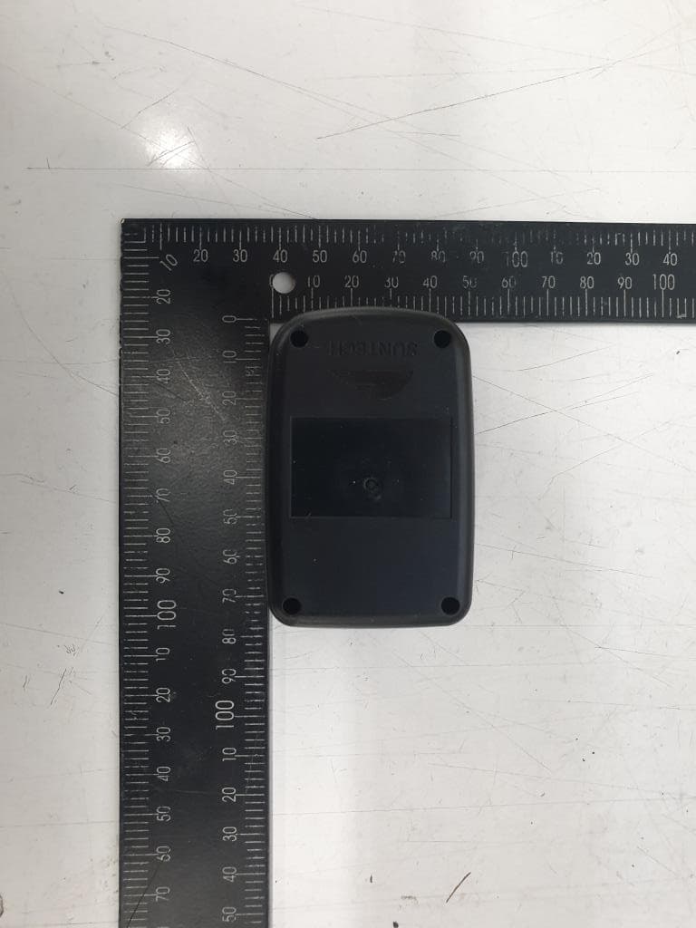
WA2ST730P
Feb 22, 2021Tracking Device
Equipment Class
DSS - Part 15 Spread Spectrum Transmitter