WA2ST240Quad band GSM GPRS Vehicle Tracker
Suntech International Ltd.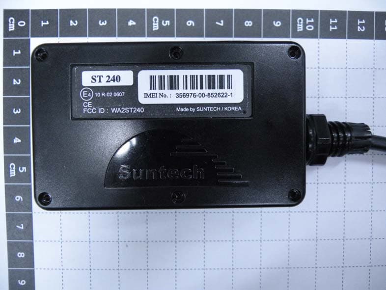
Click to zoom
Application Details
- Equipment Class
- PCB - PCS Licensed Transmitter
- Date of Grant
- Apr 28, 2013
- Application Purpose
- Original Equipment
- Date of Application
- Apr 28, 2013
- Equipment Note
- Quad band GSM GPRS Vehicle Tracker
- Frequency Range
- 1850.20000000 - 1909.80000000
- Company
- Suntech International Ltd.
- Country
- South Korea
Documents & Files
Document Text
Text extracted from the exhibit documents filed with the FCC. Open a document above to read the original.
Users Manual
ST240 User Manual Suntech International Ltd. ST240 User Manual ST240 Installation Guide 1. Decide the location of ST240 and GPS Antenna, and check the cable ways. - Check whether the location of ST 240 is far away from other electric equipment. - GPS Antenna must have a sky-view and must be far away from other antenna. 2. Insert SIM card Steps : - Open the battery cover, pick out the battery pack. - Insert SIM into holder and lock it - Plug the battery connector as shown 2 ST240 User Manual - Tighten the six screws 3. Connect Event lines with relevant lines of vehicle. Event Cable Color pin Description Red: VCC (8 - 30V) - Connect the red line to 12 VDC /24 VDC Constant power of vehicle Black: Ground - Connect the black line to Ground of vehicle - Blue: Ignition (8V - 30V) Connect the blue line to an ignition wire of vehicle Caution : Never connect the red & blue lines together to a constant power source 3 ST240 User Manual Yellow, Green, White “lines of event cable” Orange, Brown “lines of event cable” - Output line For siren or buzzer - Immobilizer . 4. Check GPS/GPRS operation and operation with LEDs. It takes 3~10 minutes for GPS connected. Green LED- indicates GPS status RED LED- indicates GPRS status Caution: Direction of ST240 is very important when installed in the vehicle. Make sure that top side of ST240 4 ST240 User Manual 5. Trouble Shooting (LED Indicator) - Blue LED: Indicates GPRS status. GPRS Blink Count Remarks Normal 1 Server Com. Error 2 <Possible Cause> 1. Server or network parameter is wrong. 2. Server is closed. 3. Temporary network barrier GPRS Com. Error 3 <Possible Cause> 1. Network parameter is wrong. 2. SIM is blocked about GPRS using. 3. Temporary network barrier 4. Weak GPRS signal 5. GPRS antenna connection is not firm. No Network 4 <Possible Cause> 1. GPRS antenna is disconnected. 2. GPRS antenna or socket of GPRS antenna is broken. 3. Device is broken. SIM PIN Locked 5 <Possible Cause> 1. SIM PIN is enabled. Cannot Attach NW 6 <Possible Cause> 1. Weak GPRS signal. 2. GPRS antenna connection is not firm. No SIM 7 <Possible Cause> 1. There is no SIM or SIM is not inserted properly. 2. SIM or SIM socket is broken. 5 ST240 User Manual - RED LED: Indicates GPS status. GPS Blink Count Remarks Normal 1 No Fix 2 <Possible Cause> 1. If power on, GPS chipset is trying to find position during some minutes. 2. GPS antenna lays on weak or no GPS signal position 3. GPS antenna connection is not firm. GPS Chipset Error GPS Antenna Error 4 <Possible Cause> 1. GPS antenna is disconnected. 2. GPS antenna or socket of GPS antenna is broken. 3. Unit is broken. The device complies with Part 15 of the FCC Rules. Operation is subject to the following two conditions: (1) this device may not cause harmful interference, and (2) this device must accept any interference received, including interference that may cause undesired operation. This equipment has been tested and found to comply with the limits for a Class B digital device, pursuant to part 15 of the FCC Rules. These limits are designed to provide reasonable protection against harmful interface in a residential installation. Cautions Modifications not expressly approved by the party responsible for compliance could void th e user’s authority to operate the equipment. FCC Radiation Exposure Statement: This equipment complies with FCC radiation exposure limits set forth for an uncontrolled environment. This equipment should be installed and operated with minimum distance 20cm between the radiator & your body. This transmitter must not be co-located or operating in conjunction with any other antenna or transmitter. NOTE : This equipment has been tested and found to comply with the limits for a Class B digital 6 ST240 User Manual device, pursuant to Part 15 of the FCC Rules. These limits are frequency energy and, if not installed and used in accordance with the instructions, may cause harmful interference to radio communications. However, there is no guarantee that interference will not occur in a particular installation. If this equipment does cause harmful interference to radio or television reception, which can be determined by turning the equipment off and on, the user is encouraged to try to correct the interference by one or more of the following measures: -- Reorient or relocate the receiving antenna. -- Increase the separation between the equipment and receiver. -- Connect the equipment into an outlet on a circuit different from that to which the receiver is connected. -- Consult the dealer or an experienced radio/TV technician for help. 7
Cover Letter(s)
Suntech International Ltd. Room 605, IT Mirae Tower, 60-21,Gasan-Dong, Geumcheon-Gu, Seoul 153-801, Korea Date: March 29, 2013 Compliance Certification Services Certification Division 561F Monterey Road Morgan Hill, CA 95037 To whom it may concern: We, the undersigned, hereby authorize Korea Testing Laboratory, to act on our behalf in all manners relating to application for equipment authorization, including signing of all documents relating to these matters. Any and all acts carried out by Korea Testing Laboratory on our behalf shall have the same effect as acts of our own. We, the undersigned, hereby certify that we are not subject to a denial of federal benefits, that includes FCC benefits, pursuant to Section 5301 of the Anti-Drug Abuse Act of 1988, 21 U.S.C. 853(a). In authorizing KTL as our agent, we still recognize that we are responsible to: a) comply with the relevant provisions of the certification program; b) make all necessary arrangements for the conduct of the evaluation, including provision for examining documentation and access to all areas, records (including internal audit reports) and personnel for the purposes of evaluation (e.g. testing, inspection, assessment, surveillance, reassessment) and resolution of complaints; c) make claims regarding certification only in respect of the scope for which certification has been granted; d) do not use our product certification in such a manner as to bring the Certification Division into disrepute and not make any statement regarding our product certification which the Certification Division may consider misleading or unauthorized; e) upon suspension or cancellation of certification, discontinue use of all advertising matter that contains any reference thereto and return any certification documents as required by the Certification Division; f) use certification only to indicate the products are certified as being in conformity with specified standards; g) endeavor to ensure that no certificate or report nor any part thereof is used in a misleading manner; h) ensure that any reference to our product certification in communication media such as documents, brochures or advertising, complies with the requirements of the Certification Division; i) keep a record of all complaints made known to the us relating to the product’s compliance with requirements of the relevant standard and to make these records available to the Certification Division when requested; j) take appropriate action with respect to such complaints and any deficiencies found in products or services that affect compliance with the requirements for certification; k) document the actions taken. This authorization is valid until further written notice from the applicant. Sincerely Yours, ---------------------------------------------- Jai Chang Yang President / CEO REMARK: 1. This authorization letter will be sent along with your application when filing with the Certification Division. 2. Please follow the format and type it on company letterhead and send original to us.
Cover Letter(s)
Suntech International Ltd. Room 605, IT Mirae Tower, 60-21, Gasan-Dong, Geumcheon-Gu, Seoul 153-801, Korea E-MAIL : [email protected] Federal Communications Commission Authorization and Evaluation Division Confidentiality Request regarding application for certification of FCC ID : WA2ST240 Pursuant to Sections 0.457 and 0.459 of the Commission’s Rules, we hereby request confidential treatment of information accompanying this application as outlined below: 1. Block Diagram 2. Schematic Diagram 3. Operational description 4. Part list 5. Tune up info The above material contains trade secrets or technical data, which would customarily be guarded from competitors. We do not want these documents to be accessible to the general public. The public disclosure of these materials may be harmful to the applicant and provide unjustified benefits to its competitors. The applicant understans that pursuant ot Section 0.457 of the Rules, disclosure of this application and all accompanying documentation will not be made before the date of the Grant for this application. Sincerely, ----------------------------------------------- 05 th of March, 2013 Jai Chang Yang President / CEO
External Photos
Model number : ST240 Photographs (Outside) Model number : ST240 Photographs (Outside) Model number : ST240 Photographs (Outside) Model number : ST240 Photographs (Outside)
ID Label/Location Info
Model Number : ST240 Label Information
Internal Photos
Model number : ST240 Photographs (Inside) Model number : ST240 Photographs (Inside)
Test Report
Report No.: 12-065885-01-01 Page 1 of 26 Pages 723, Haean-ro, Sangnok-gu, Ansan-si, Gyeonggi-do, KOREA (426-901) Tel. : +82-31-5000-132 http://www.ktl.re.kr Fax. : +82-31-5000-147 FP-204-03-01 TEST REPORT 1. Applicant Name : Suntech International Ltd. Address : Room 605, IT Mirae Tower, 60-21, Gasan-Dong, Geumcheon-Gu, Seoul, Korea 2. Products Name : Quad band GSM/GPRS Vehicle Tracker Model/Type : ST240 Manufacturer : Suntech International Ltd. 3. Test Standard : FCC CFR 47 Part 2, Part 22(H), Part 24(E) 4. Test Method : ANSI/TIA/EIA-603-C, ANSI C63.4-2009 5. Test Result : Positive 6. Date of Application : December 03, 2012 7. Date of Issue : April 04, 2013 Tested by Approved by Sung-kyu Cho Jeong-min Kim Telecommunication Center Engineer Telecommunication Center Manager The test results contained apply only to the test sample(s) supplied by the applicant, and this test report shall not be reproduced in full or in part without approval of the KTL in advance. Report No.: 12-065885-01-01 Page 2 of 26 Pages 723, Haean-ro, Sangnok-gu, Ansan-si, Gyeonggi-do, KOREA (426-901) Tel. : +82-31-5000-132 http://www.ktl.re.kr Fax. : +82-31-5000-147 FP-204-03-01 TABLE OF CONTENTS 1. GENERAL INFORMATIONS .................................................................................................. 4 1.1. Applicant (Client) .............................................................................................................................................. 4 1.2. Equipment (EUT) ............................................................................................................................................... 4 1.3. Testing Laboratory ............................................................................................................................................ 5 1.4. Description of test mode .................................................................................................................................. 6 2. SUMMARY OF TEST RESULTS ............................................................................................ 7 3. MEASUREMENT & RESULTS ............................................................................................... 8 3.1. Conducted Output Power ................................................................................................................................. 8 3.1.1. Test Procedure ......................................................................................................................................... 8 3.1.2. Test Results .............................................................................................................................................. 8 3.2. Effective Radiated Power ................................................................................................................................. 9 3.2.1. Test Procedure ......................................................................................................................................... 9 3.2.2. Limit .......................................................................................................................................................... 9 3.2.3. Test Result ............................................................................................................................................. 10 3.3. Field Strength of Spurious Radiation ........................................................................................................... 11 3.3.1. Test Results (GSM850 test data) ........................................................................................................... 11 3.3.2. Test Results (GSM1900 test data) ......................................................................................................... 12 3.4. Occupied Bandwidth ...................................................................................................................................... 13 3.4.1. Test Procedure ....................................................................................................................................... 13 3.4.2. Limit ........................................................................................................................................................ 13 3.4.3. Test Results ............................................................................................................................................ 14 3.5. Conducted Spurious Emission.................................................................................................................... 17 3.5.1. Test Procedure ....................................................................................................................................... 17 3.5.2. Limit ........................................................................................................................................................ 17 3.5.3. Test Results ............................................................................................................................................ 17 3.6. Frequency Stability / Temperature Variation ................................................................................... ............. 23 3.6.1. Test Procedure ....................................................................................................................................... 23 Report No.: 12-065885-01-01 Page 3 of 26 Pages 723, Haean-ro, Sangnok-gu, Ansan-si, Gyeonggi-do, KOREA (426-901) Tel. : +82-31-5000-132 http://www.ktl.re.kr Fax. : +82-31-5000-147 FP-204-03-01 3.6.2. Limit ........................................................................................................................................................ 23 3.6.3. Test Results ............................................................................................................................................ 24 4. TEST EQUIPMENTS .........................…
Text truncated - open the document above for the full version.
Test Setup Photos
Model Number : ST240 Test setup Photo Model Number : ST240
Contact Information
Applicant
Hun Shin(Manager)
Test Firm
Korea Testing LaboratoryYang-hyun Kim
Technical Specifications
| # | Rule Parts | Frequency Range | Power Output | Emission | Tolerance |
|---|---|---|---|---|---|
| 2 | 24E | 1.85 GHz - 1.91 GHz | 1.364 W | 244KGXW | 2.5 ppm |
Other Applications from Suntech International Ltd.
WA2ST8000NA
May 12, 2026Tracking Device
Equipment Class
JAD - Part 15 Class A Digital DeviceWA2ST4315BN
Feb 27, 2026Tracking Device
Equipment Class
DTS - Digital Transmission SystemWA2ST6952
Dec 22, 2025Tracking Device
Equipment Class
DTS - Digital Transmission SystemWA2ST4930
Jan 21, 2024Tracking Device
Equipment Class
DTS - Digital Transmission System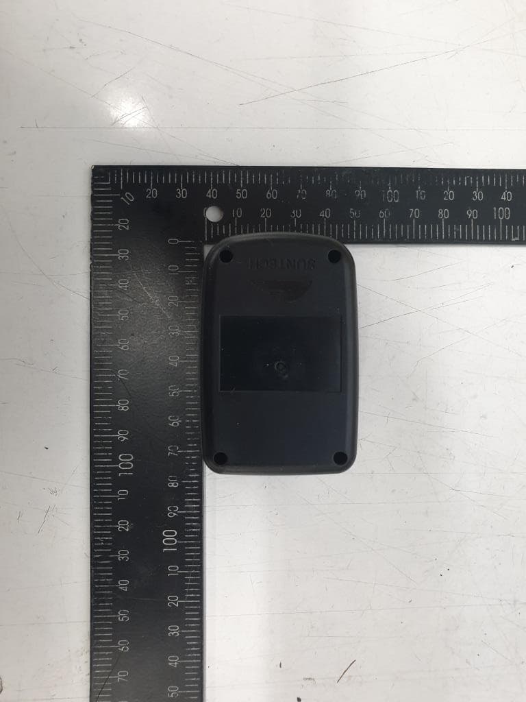
WA2ST730P
Feb 22, 2021Tracking Device
Equipment Class
DSS - Part 15 Spread Spectrum Transmitter