WAZSKEA7A01Smart Keyless System (Smart Unit)
Mitsubishi Electric Corporation Himeji works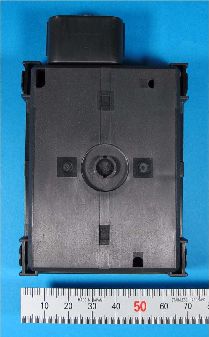
Click to zoom
Application Details
- Equipment Class
- CYY - Communications Receiver used w/Pt 15 Transmitter
- Date of Grant
- Feb 26, 2014
- Application Purpose
- Original Equipment
- Date of Application
- Feb 26, 2014
- Equipment Note
- Smart Keyless System (Smart Unit)
- Frequency Range
- 315.00000000 - 315.00000000
- Country
- Japan
Documents & Files
Document Text
Text extracted from the exhibit documents filed with the FCC. Open a document above to read the original.
Users Manual
Since this device is always used with vehicle, it is not sold to general end users separately. Therefore there is no user manual of this device by alone. This document is an excerpt from a user manual of vehicle. FCC WARNING Changes or modifications not expressly approved by the party responsible for compliance could void the user’s authority to operate the equipment. FCC/IC This device complies with Part 15 of FCC Rules and Industry Canada licence-exempt RSS standard(s). Operation is subject to the following two conditions: (1) this device may not cause interference, and (2) this device must accept any interference, including interference that may cause undesired operation of this device. Le présent appareil est conforme aux la Partie 15 des règles de la FCC et CNR d'Industrie Canada applicables aux appareils radio exempts de licence. L'exploitation est autorisée aux deux conditions suivantes: (1) l'appareil ne doit pas produire de brouillage, et (2) l'utilisateur (2) l'utilisateur de l'appareil doit accepter tout brouillage radioélectrique subi, même si le brouillage est susceptible d'en compromettre le fonctionnement. 3-1 123456789 101112 SMART KEY SYSTEM EAU61660 Smart key systemThe smart key system enables the fol-lowing operations to be carried outwithout using a mechanical key. Power “ON/OFF” Engine start and stop Steering lock release and locking Seat lock release TIP To preserve battery power, the smartkey will turn off automatically about aweek after the vehicle is last used. Turnthe smart key on before using the vehi-cle again. WARNING EWA14703 Keep implanted pacemakersand defibrillators, as well as oth-er electric medical devices awayfrom the smart key system an-tenna (see illustration). Radio waves transmitted by theantenna may affect the opera-tion of such devices when closeby. If you have an electric medicaldevice, consult a doctor or the device manufacturer about anyrisk of possible interference be- fore using this vehicle. NOTICE ECA15762 The smart key system uses weak ra-dio waves. The smart key systemmay not work normally in the follow-ing situations. When the smart key is placed ina location exposed to strong ra-dio waves or other electromag-netic noise. When there are facilities nearbythat are emitting strong radiowaves e.g. TV towers, powerplants, broadcasting stations, airports etc. When you are carrying or usingcommunication equipmentsuch as radios or mobilephones in close proximity of thesmart key. When the smart key is in contactwith or covered by metallic ob-jects. When other vehicles equippedwith a smart key system arenearby. In such situations, move the smartkey to another location and performthe operation again. If it still doesnot work, use the mechanical key tocarry out the operation in emergen- cy mode (refer to Page 6-1). 1. Vehicle mounted antenna 1 SMART KEY SYSTEM 3-2 123456789 101112 EAU61640 Handling of mechanical key and smart key WARNING EWA17950 The smart key should be carriedby the driver. Do not store it onthe vehicle. When the smart key is within op-erating range, exercise due carebecause other people not carry-ing the smart key can also startthe engine or operate the vehi-cle. Included with the vehicle are onesmart key, one smart key identifi-cation tag, one mechanical keyand one mechanical key identifica-tion tag. Keep the mechanical keyand tag separate from the smartkey and tag. Should you lose thesmart key, the mechanical key willserve as a back up. We also rec-ommend that you note down theidentification number in a just in case you lose the identificationtag. If the smart key and tag are lost ordamaged, and there is no record ofthe identification number, all theparts of the smart key system willneed to be replaced. The identification number of thesmart key is displayed on the in-side of the smart key. The smartkey identification number (6 digits)and mechanical key identificationnumber (1 letter + 4 digits) are dis-played on the two respective iden-tification tags as well. By inputting the identification number of thesmart key in an emergency, theengine can be started and the var-ious locks can be released withoutusing the smart key. Please referto emergency mode on page 6-1on how to operate the smart keysystem in an emergency. NOTICE ECA21570 The smart key has precision elec-tronic components. Observe the fol-lowing precautions to preventpossible malfunction or damage. Do not drop,bend, or subject thesmart key to strong impacts. Do not allow the smart key to 1. Mechanical key2. Smart key3. Smart key identification number tag4. Mechanical key5. Mechanical key identification number tag 12 345 1. ID number 1 1 SMART KEY SYSTEM 3-3 123456789 101112 get wet. Do not put heavy objects on topof the smart key. Do not leave the smart key in aplace exposed to direct sun-light, high temperature, or highhumidity. Do not cut, drill, or attempt tomodify the smart key. Keep the smart key away fromstrong magnetic fields and mag-netic objects such as key hold-ers, TVs, and computers. Keep the smart key away fromelectric medical equipment. Do not allow oils, polishingagents, fuel, or any strongchemicals to come in contactwith the smart key. The smartkey body may become discol-ored or crack. TIP The expected battery life is ap-proximately 2 years, but this mayvary according to operating condi-tions. The smart key uses battery powereven when it is away from the ve- hicle. If the smart key continually re-ceives radio waves, the battery willdischarge quickly in reaction tothis. (For example, when placed inthe vicinity of electrical productssuch as televisions, radios, orcomputers.) Replace the battery when thesmart key system indicator lightflashes for 20 seconds when thepower of the vehicle is turned on.(Refer to page 3-4 on how to re-place the battery) If the smart key system indicatorlight does not come on when youpress the lock / unlock switch, thesmart key battery may be dis-charged or the smart k…
Text truncated - open the document above for the full version.
External Photos
【 Confidential 】 Model : SKEA7A-01 TOP LEFT FACE RIGHT BACK BOTTOMSmart Keyless System (Smart Unit) PHOTO_6 Smart Unit_SKEA7A01
ID Label/Location Info
【 Confidential 】 Model : SKEA7A-01 Label display * * There is no sufficient space and this product will be installed in the motorcycle, therefore labelling requirement will be described in the users manual. Smart Keyless System Label (Smart Unit) MITSUBISHI ELECTRIC CORP.,JAPAN FCC ID:WAZSKEA7A01MODEL:SKEA7A-01IC:662F-SKEA7A01CCAB14LPXXX0TX 2PW-86260-10 F8T75771 YMDD S/N:000001 Label Label Smart Unit_SKEA7A01_fcc
Internal Photos
【 Confidential 】 Model : SKEA7A-01 BAC K FACE Smart Keyless System (Smart Unit) PHOTO PCB ASSY Smart Unit_SKEA7A01
Internal Photos
【 Confidential 】 Model : SKEA7A-01 FACE BAC K Smart Keyless System (Smart Unit) Bar antenna PHOTO PCB ASSY Smart Unit_SKEA7A01
Test Report
Test report No. : 10131705H-C-R2 Page : 2 of 15 Issued date : February 14, 2014 Revised date : February 28, 2014 FCC ID : WAZSKEA7A01 UL Japan, Inc. Head Office EMC Lab. 4383-326 Asama-cho, Ise-shi, Mie-ken 516-0021 JAPAN Telephone : +81 596 24 8999 Facsimile : +81 596 24 8124 REVISION HISTORY Original Test Report No.: 10131705H-C Revision Test report No. Date Page revised Contents - (Original) 10131705H-C February 14, 2014 - - 1 10131705H-C-R1 February 21, 2014 All page Deletion of all the items about Conducted Emission. 2 10131705H-C-R2 February 28, 2014 P.4 Deletion of Frequency band in Section 2.2. Test report No. : 10131705H-C-R2 Page : 3 of 15 Issued date : February 14, 2014 Revised date : February 28, 2014 FCC ID : WAZSKEA7A01 UL Japan, Inc. Head Office EMC Lab. 4383-326 Asama-cho, Ise-shi, Mie-ken 516-0021 JAPAN Telephone : +81 596 24 8999 Facsimile : +81 596 24 8124 CONTENTS PAGE SECTION 1: Customer information ...................................................................................... 4 SECTION 2: Equipment under test (E.U.T.) ........................................................................ 4 SECTION 3: Test specification, procedures & results ......................................................... 4 SECTION 4: Operation of E.U.T. during testing ................................................................. 7 SECTION 5: Radiated Emission ............................................................................................ 9 APPENDIX 1: Data of EMI test ........................................................................................... 10 Radiated Emission ....................................................................................................................... 10 APPENDIX 2: Test instruments ........................................................................................... 12 APPENDIX 3: Photographs of test setup............................................................................. 13 Radiated Emission ....................................................................................................................... 13 Worst Case Position (Horizontal: X-axis/ Vertical:X-axis) ..................................................... 14 Test report No. : 10131705H-C-R2 Page : 4 of 15 Issued date : February 14, 2014 Revised date : February 28, 2014 FCC ID : WAZSKEA7A01 UL Japan, Inc. Head Office EMC Lab. 4383-326 Asama-cho, Ise-shi, Mie-ken 516-0021 JAPAN Telephone : +81 596 24 8999 Facsimile : +81 596 24 8124 SECTION 1: Customer information Company Name : Mitsubishi Electric Corporation Himeji works Address : 840 Chiyoda-machi Himeji Hyogo, 670-8677, Japan Telephone Number : +81-79-298-7363 Facsimile Number : +81-79-298-9929 Contact Person : Shinichi Furuta SECTION 2: Equipment under test (E.U.T.) 2.1 Identification of E.U.T. Type of Equipment : Smart Keyless System (Smart Unit) Model No. : SKEA7A-01 Serial No. : Refer to Section 4, Clause 4.2 Rating : DC12.0V Receipt Date of Sample : January 21, 2014 Country of Mass-production : Japan Condition of EUT : Production prototype (Not for Sale: This sample is equivalent to mass-produced items.) Modification of EUT : No Modification by the test lab 2.2 Product Description Model No: SKEA7A-01 (referred to as the EUT in this report) is the Smart Keyless System (Smart Unit). The clock frequency of EUT is 10 MHz (CPU) and 29.509394MHz (RF receiving IC). Radio Specification LF Part * Equipment Type : Transmitter Type of modulation : ASK Bandwidth : 2.5kHz Frequency of operation : 125kHz Other clock frequency : 29.509394MHz Antenna Type : Inductive Method of Frequency Generation : Crystal Operating voltage (inner) : DC +12.0V RF Part Type of Receiver : Receiver Frequency of operation : 315MHz Other clock frequency : 10MHz Intermediate frequency : 220kHz Antenna Type : Bar Antenna Method of Frequency Generation : Crystal Operating voltage (inner) : DC +5.0V * EUT also has this function. Please refer to No. 10131705H-A-R2 (FCC15C). FCC15.111(b) The receiving antenna (of this EUT) is installed inside the EUT and cannot be removed (permanently attached). Therefore, Radiated emission test was performed. Test report No. : 10131705H-C-R2 Page : 5 of 15 Issued date : February 14, 2014 Revised date : February 28, 2014 FCC ID : WAZSKEA7A01 UL Japan, Inc. Head Office EMC Lab. 4383-326 Asama-cho, Ise-shi, Mie-ken 516-0021 JAPAN Telephone : +81 596 24 8999 Facsimile : +81 596 24 8124 SECTION 3: Test specification, procedures & results 3.1 Test specification Test specification : FCC Part 15 Subpart B: 2013, final revised on September 30, 2013 and effective October 30, 2013 Title : FCC 47CFR Part15 Radio Frequency Device Subpart B Unintentional Radiators 3.2 Procedures and results Item Test Procedure Limits DeviationWorst margin Result Conducted emission FCC: ANSI C63.4: 2003 7. AC powerline conducted emission measurements Class B N/A N/A N/A *1) IC: ICES-003 Issue 5: 2012 Radiated emission FCC: ANSI C63.4: 2003 8. Radiated emission measurements Class B N/A 19.0dB 867.379MHz Vertical, QP Complied IC: ICES-003 Issue 5: 2012 *Note: UL Japan, Inc’s EMI Work Procedure 13-EM-W0420. *1) The test is not applicable since the EUT is not the device that is designed to be connected to the public utility (AC) power line. 3.3 Addition to standard No addition, exclusion nor deviation has been made from the standard. 3.4 Uncertainty EMI The following uncertainties have been calculated to provide a confidence level of 95% using a coverage factor k=2. Test room (semi- anechoic chamber) Radiated emission (3m*)(+dB) (1m*)(+dB) (0.5m*)(+dB) 9kHz -30MHz 30MHz -300MHz 300MHz -1GHz 1GHz -10GHz 10GHz -18GHz 18GHz -26.5GHz 26.5GHz -40GHz No.1 4.0dB 5.1dB 5.0dB 5.1dB 6.0dB 4.9dB 4.3dB No.2 3.9dB 5.2dB 5.0dB 4.9dB 5.9dB 4.7dB 4.2dB No.3 4.3dB 5.1dB 5.2dB 5.2dB 6.0dB 4.8dB 4.2dB No.4 4.6dB 5.2dB 5.0dB 5.2dB 6.0dB 5.7dB 4.2dB *3m/1m/0.5m = Measurement distance Radiated emission test(3m) The data listed in this test r…
Text truncated - open the document above for the full version.
Test Setup Photos
Test report No. : 10131705H-C-R2 Page : 13 of 15 Issued date : February 14, 2014 Revised date : February 28, 2014 FCC ID : WAZSKEA7A01 UL Japan, Inc. Head Office EMC Lab. 4383-326 Asama-cho, Ise-shi, Mie-ken 516-0021 JAPAN Telephone : +81 596 24 8999 Facsimile : +81 596 24 8124 APPENDIX 3: Photographs of test setup Radiated Emission Photo 1 Photo 2 Test report No. : 10131705H-C-R2 Page : 14 of 15 Issued date : February 14, 2014 Revised date : February 28, 2014 FCC ID : WAZSKEA7A01 UL Japan, Inc. Head Office EMC Lab. 4383-326 Asama-cho, Ise-shi, Mie-ken 516-0021 JAPAN Telephone : +81 596 24 8999 Facsimile : +81 596 24 8124 Worst Case Position (Horizontal: X-axis/ Vertical:X-axis) X-axis Y-axis Z-axis Test report No. : 10131705H-C-R2 Page : 15 of 15 Issued date : February 14, 2014 Revised date : February 28, 2014 FCC ID : WAZSKEA7A01 UL Japan, Inc. Head Office EMC Lab. 4383-326 Asama-cho, Ise-shi, Mie-ken 516-0021 JAPAN Telephone : +81 596 24 8999 Facsimile : +81 596 24 8124 4.2 Configuration and peripherals A B 1 2 DC 12.0V *Cabling and setup were taken into consideration and test data was taken under worse case conditions. Description of EUT and Support equipment No. Item Model number Serial number Manufacturer Remark A Smart Keyless System (Smart Unit) SKEA7A-01 20140117-E1(No.1)Mitsubishi Electric Corporation Himeji works EUT B Switch Box 1 - No.17 Mitsubishi Electric Corporation Himeji works - List of cables used No. Name Length (m) Shield Remarks Cable Connector 1 DC Cable 1.5 Unshielded Unshielded - 2 Signal Cable 1.5 Unshielded Unshielded - End of Report
Contact Information
Applicant
Tomoko Masuda
Technical Contact
UL Japan, Inc.Masanori Nishiyama
[email protected]81-596-24-8999
4383-326 Asama-cho, Ise-shi · Mie-ken · Japan
Test Firm
UL Japan, Inc. Head office EMC Lab.Tetsuya Hashimoto
Technical Specifications
| # | Rule Parts | Frequency Range | Power Output |
|---|---|---|---|
| 1 | 15B | 315 MHz - 315 MHz | - |
Other Applications from Mitsubishi Electric Corporation Himeji works
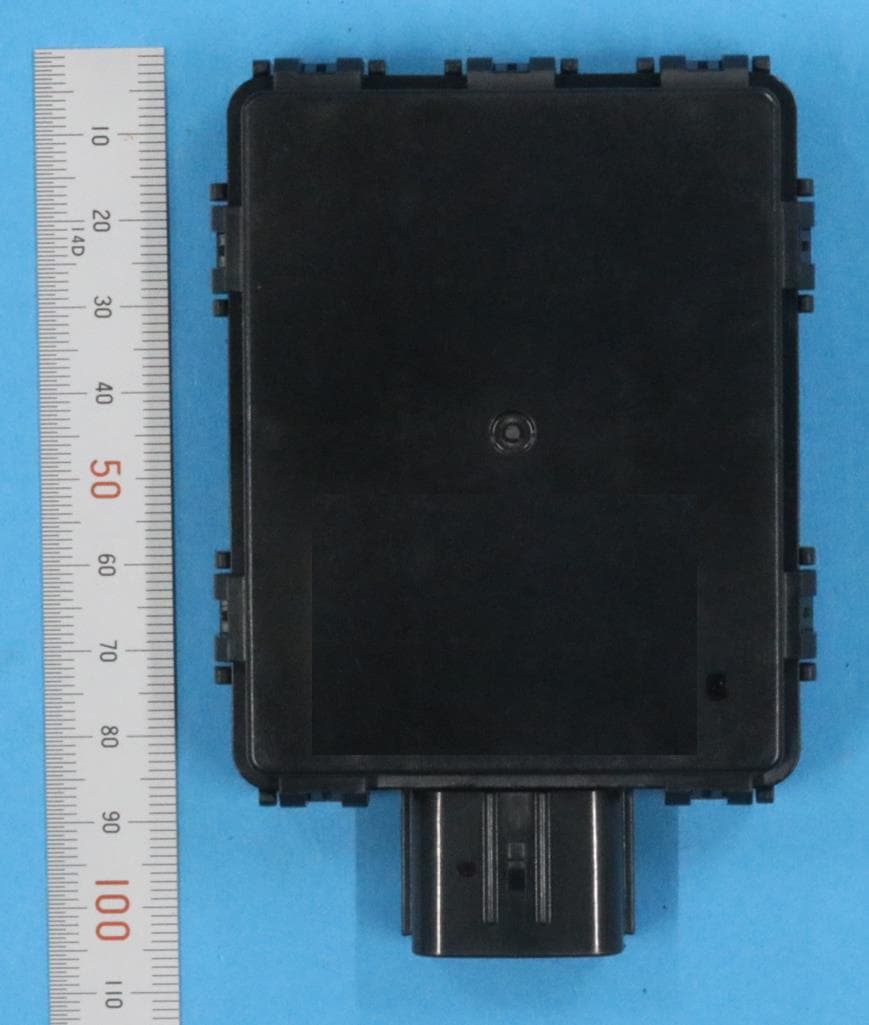
WAZSKEA7D05
Sep 25, 2023Smart Keyless System Smart Unit
Equipment Class
CYY - Communications Receiver used w/Pt 15 Transmitter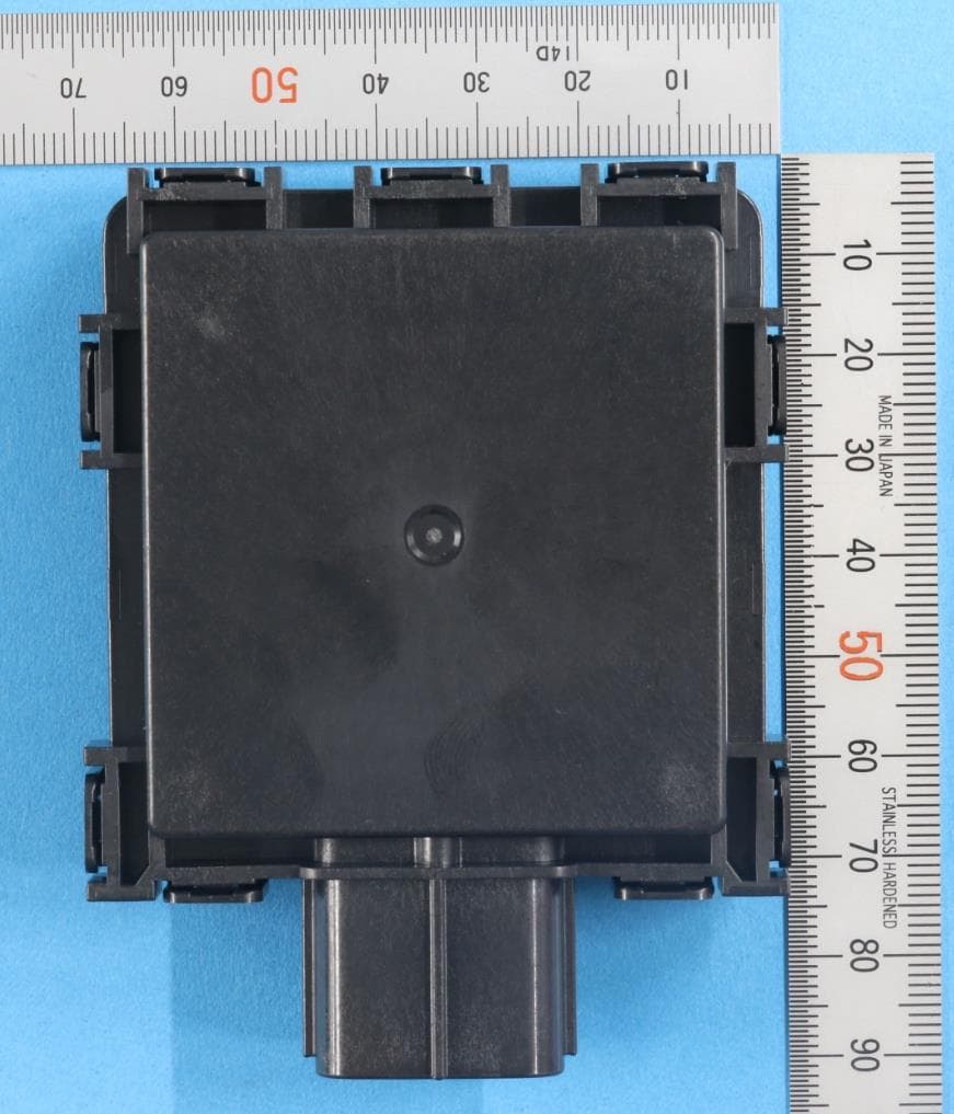
WAZSKEA7D06
Aug 27, 2023Smart Keyless System Smart Unit
Equipment Class
CYY - Communications Receiver used w/Pt 15 TransmitterWAZSKE8AD03
Jul 19, 2022Smart Keyless System (Smart Unit)
Equipment Class
CYY - Communications Receiver used w/Pt 15 Transmitter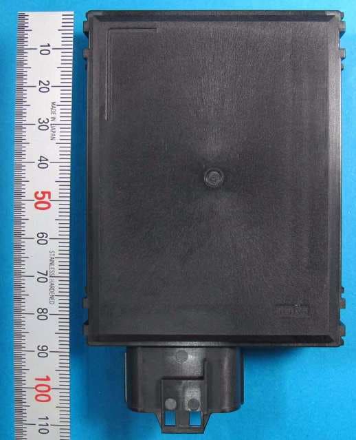
WAZSKE45A03
Dec 24, 2020Smart Keyless System Smart Unit
Equipment Class
CYY - Communications Receiver used w/Pt 15 Transmitter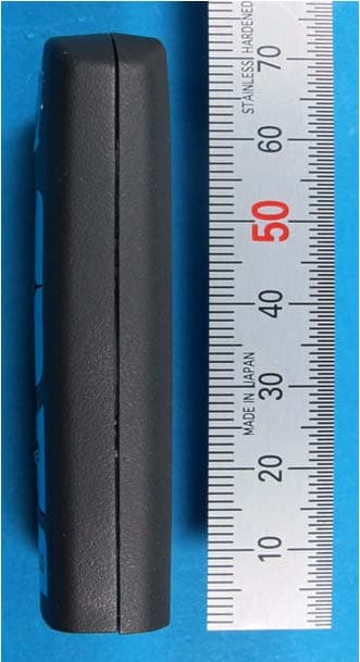
WAZSKE13D02
Dec 14, 2015Keyless System Hand Unit
Equipment Class
DSC - Part 15 Security/Remote Control Transmitter