WCO-DS101Intelligent Diaper Dock Station
Microtips Technology Inc.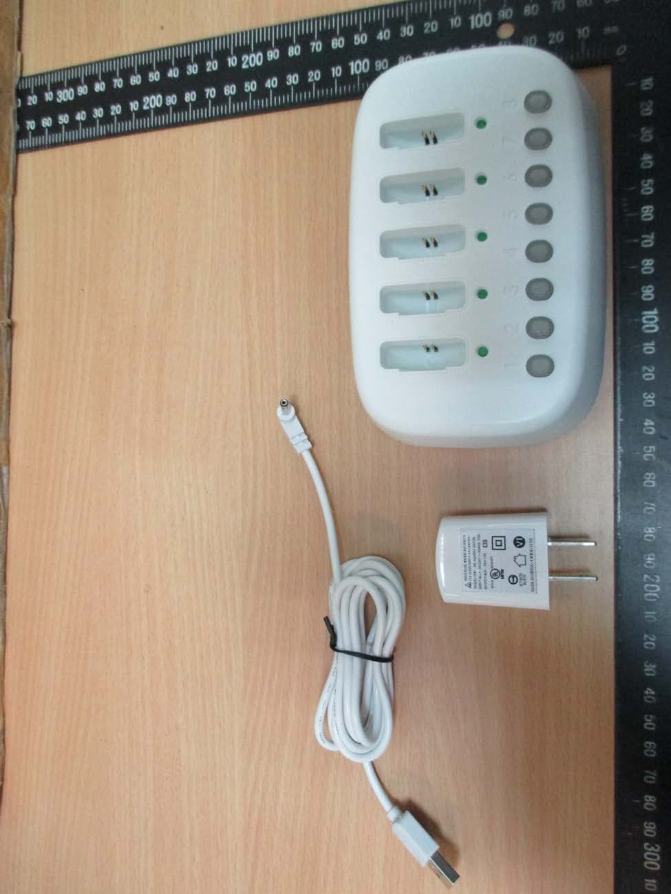
Click to zoom
Application Details
- Equipment Class
- DTS - Digital Transmission System
- Date of Grant
- Mar 02, 2020
- Application Purpose
- Original Equipment
- Date of Application
- Mar 02, 2020
- Equipment Note
- Intelligent Diaper Dock Station
- Frequency Range
- 2402.00000000 - 2480.00000000
- Company
- Microtips Technology Inc.
- Country
- Taiwan
Documents & Files
Document Text
Text extracted from the exhibit documents filed with the FCC. Open a document above to read the original.
Users Manual
Omago Smart Diaper Sensor Dock User Manual Thank you for purchasing Omago Intelligent Diaper Sensor. Please read this user manual in detail and follow up the instruction. *** Omago Intelligent Diaper Sensor is not included, you can purchase it separately Instructions Charge Omago Intelligent Diaper Sensor before starting to use. The device will be a normal state by the indicator from LED_1 to LED_8 flickering back and forth one time. 1.Pairing the Dock with the Intelligent Diaper S ensor The Dock can pair with up to 8 Smart Diaper Sensors. You can get every paired Smart Diaper sensor status by the led on Dock. Please select the sensor link button on the Dock, such as 1. After pressing the link button, the button led will flash blue. Ta ke one Intelligent Diaper Sensor and press the connection button for 3- 5 seconds for pairing. The link button led will become constant blue if pairing successfully. If not, please repeat the link process. Please pair all these 8 Intelligent Diaper Sensor by the above process and one by one each time. You can number the Intelligent Diaper Sensors by a sticker for corresponding to the link button on Dock. 2.Battery charge Omago Intelligent Diaper Sensor uses a built-in rechargeable battery. Before starting to use, please insert the sensor into charge slot for charging the battery completely. When the link button led on Dock flashing purple, please inert the sensor into charge slot for charging. The charging led will become constant green after complete charging. 3.Intelligent Diaper S ensor re-paired with the Dock When the sensor inserting to charge slot for charging, it will be automatically unpaired with the corresponding link button on the Dock. The link button will flash blue. You can press the link button off. Take a new unpaired Intelligent Diaper Sensor and re-pair it with this link button by the above pairing process and numbering. If the Intelligent Diaper Sensor is out of connection range, the link button led on Dock will flash blue and sensor led will flash red. For example, if the baby is carried away from the nursery room (the link button corresponding to the Dock will flash blue and the sensor flashes red), it will automatically connect to the Dock again when coming back to the nursery room. 4.Pu t Smart Diaper Sensor into strap and stick to the position of the diaper corresponding to the human excretory hole to get the best effect. 5.Whe n the Sensor detects PEE volume of the diaper has reached a certain level or the stool, the breathing led o n the Dock will flash, and the corresponding sensor connection button will flash blue and red. Please change the diaper for cleaning purposes. After changing the diaper, the Dock breathing led will be off and the link button turns constant blue. Federal Communication Commission Interference Statement This equipment has been tested and found to comply with the limits for a Class B digital device, pursuant to Part 15 of the FCC Rules. These limits are designed to provide reasonable protection against harmful interference in a residential installation. This equipment generates, uses and can radiate radio frequency energy and, if not installed and used in accordance with the instructions, may cause harmful interference to radio communications. However, there is no guarantee that interference will not occur in a particular installation. If this equipment does cause harmful interference to radio or television reception, which can be determined by turning the equipment off and on, the user is encouraged to t ry to correct the interference by one of the following measures: . Reorient or relocate the receiving antenna. . I ncrease the separation between the equipment and receiver. . Connect the equipment into an outlet on a circuit different from that to which the receiver is connected. . Consult the dealer or an experienced radio/TV technician for help. FCC Caution: To assure continued compliance, any changes or modifications not expressly approved by the party responsible for compliance could void the user's authority to operate this equipment. (Example - use only shielded interface cables when connecting to computer or peripheral devices). FCC Radiation Exposure Statement This equipment complies with FCC RF radiation exposure limits set forth for an uncontrolled envi ronment. This equipment should be installed and operated with a minimum distance of 20 centimeters between the radiator and your body. This transmitter must not be co-located or operating in conjunction with any other antenna or transmitter. The antennas used for this transmitter must be installed to provide a separation distance of at least 20 cm from all persons and must not be co-located or operating in conjunction with any other antenna or transmitter. This device complies with Part 15 of the FCC Rules. Operation is subject to the following two conditions: (1) This device may not cause harmful interference, and (2) This device must accept any interference received, including interference that may cause undesired operation.
Cover Letter(s)
RF_160, Issue 04 (On manufacturer’s company letter heading) Declaration of Authorization We Name: Microtips Technology Inc. Address: 12F, No.31, Lane 169, Kang-Ning St., Hsi-Chih District, City: New Taipei City 221, Country: Taiwan, R.O.C Declare that: Name Representative of agent: Rita Lin (1) Agent Company name: Worldwide Testing Services (Taiwan) Co., Ltd Address: 6F., No. 58, Lane 188, Ruey Kuang Road, Neihu, City: Taipei 114 Country Taiwan is authorized to apply for Certification of the following product(s): Product description: Intelligent Diaper Dock Station Type designation: DS-101 Trademark: Omago Validity/ expiry date on our behalf. Date: 2020/02/03 City: New Taipei City Name: Thomas CHOU (2) Function: Product Manager Signature: Notes: (1): Required for FCC application (2): For FCC it must be the Grantee Code “owner” or the authorized agent.
Cover Letter(s)
FCC, Request for non-disclosure Date: 21-Nov-2018 RF_501, Issue 8 Page 1 of 1 Company Name: Microtips Technology Inc. Address : 12F, No.31, Lane 169, Kang-Ning St., Hsi-Chih District, City: New Taipei City 221, Country: Taiwan, R.O.C To: Telefication B.V., Dept. FCC TCB Edisonstraat 12A 6902 PK ZEVENAAR The Netherlands Subject: Request for confidentiality FCC ID: WCO-DS101 Reference number: ###### Dear FCC TCB, 1. Long-Term Confidentiality Pursuant to 47 CFR Section 0.459(a) & (b), we hereby requests non-disclosure and confidential treatment of the following materials submitted in support of FCC certification application: Bill(s) of Material Block Diagrams Operational Description Schematic Diagrams Tune-up Procedure Above materials contain secrets, proprietary and technical information, which would customarily be guarded from competitors under 47 CFR, section 0.457(d)(2). Disclosure or publication or any portion of this company confidential material to other parties could cause substantial competitive harm and provide unjustified benefits for competitors. 2. Short-Term Confidentiality (STC) Pursuant to Public Notice DA 04-1705 of the Commission’s policy, in order to comply with the marketing regulations in 47 CFR §2.803 and the importation rules in 47 CFR §2.1204, a pplicant hereby requests Short-Term Confidential treatment of the following materials (See notes below): Internal Photos User’s Manual Test Set-up Photos External Photos Justification: Date: 2020-02-03 Name and signature of applicant: Thomas CHOU Notes: 1) A document or type of document can only have ONE type of confidentiality! 2) Short-Term confidentiality is in principle for 45 days from date of grant; it can be extended max 3 times (total time 180 days max.)! The planned date should stated in the RF731 application form. 3) FCC must be informed when marketing begins earlier. 4) Release takes place automatically thus extension must be requested in time. Telefication does not remind you of this! 5) Request for extension or for release must be received by Telefication at least 7 days before date of actual marketing or before expiration of the STC period
Cover Letter(s)
承 認 書 SPECIFICATION FOR APPROVAL 客戶名稱 CUSTOMER : 客戶料號 CUSTOMER’S P/N : 料號 PART NUMBER : WAN3216F245W36 規格 DESCRIPTION : Chip Antenna 3216 M-Ant 2.45G Type 36 版本 VERSION : V2.0 日期 ISSUE DATE : 2016/08/04 客 戶 承 認 CUSTOMER APPROVED 工 程 部 R&D CENTER 承 認 APPROVAL 確 認 CHECKED 製 作 DRAWN Ray Thor Rocky 富廷科技股份有限公司 Hong Kong RIMON TECHNOLOGY CO., LTD. RIMON TECHNOLOGY CO., LTD. 香港九龍旺角彌敦道582-592號信和中心804室 114台北市內湖區內湖路2段352號4樓之6 RM804, Sino Centre., 582-592 Nathan Rd., Kln, Hong Kong 4F-6, No.352, Sec. 2, Neihu Rd., Neihu District,Taipei 114, Taiwan 電話: +886-2-2796-2568 傳真: +886-2-2796-6433 E-mail : [email protected] 3216 Chip antenna For Bluetooth / WLAN Applications RIMON TECHNOLOGY CO., LTD. 2/11 Dimension (mm) L 3.23 ± 0.20 W 1.66 ± 0.20 T 1.23 ± 0.20 P/N:WAN3216F245W36 Part Number Information WAN 3216 F 245 W 36 A B C D E F A Product Series Antenna B Dimension L x W 3.2X1.6mm (+‐0.2mm) C Material High K material D Working Frequency 2.4 ~ 2.5GHz E Feeding mode Function Antenna F Antenna type Type=36 1. Electrical Specification Specification Part Number WAN3216F245W36 Central Frequency 2450 MHz Bandwidth 100 (Min.) MHz Return Loss ‐6.5 (Max) dB Peak Gain 2.71 dBi Impedance 50 Ohm Operating Temperature ‐40~+85 °C Maximum Power 4 W Resistance to Soldering Heats 10 ( @ 260°C) sec. Polarization Linear Azimuth Beamwidth Omni‐directional Termination Cu / Sn (Leadless) Remark : Bandwidth & Peak Gain was measured under evaluation board of next page RIMON TECHNOLOGY CO., LTD. 3/11 2. Recommended PCB Pattern Evaluation Board Dimension Suggested Matching Circuit RIMON TECHNOLOGY CO., LTD. 4/11 Layout Dimensions in Clearance area (Size=5.2*5.0mm) RIMON TECHNOLOGY CO., LTD. 5/11 50 ohm transmission Line Matching Circuit FootPrint (Unit : mm) 3. Measurement Results Return Loss RIMON TECHNOLOGY CO., LTD. 6/11 Radiation Pattern Y RIMON TECHNOLOGY CO., LTD. 7/11 X Z Efficiency Peak Gain Directivity 2400MHz 55.21 % 1.45 dBi 5.32 dBi 2450MHz 66.45 % 2.71 dBi 5.21 dBi 2500MHz 57.53 % 1.98 dBi 5.29 dBi Chamber Coordinate System 4. Reliability and Test Condictions ITEM REQUIREMENTS TEST CONDITION Solderability 1. Wetting shall exceed 90% coverage 2. No visible mechanical damage Pre‐heating temperature:150°C/60sec. Solder temperature:230±5°C Duration:4±1sec. Solder:Sn‐Ag3.0‐Cu0.5 Flux for lead free: rosin Solder heat Resistance 1. No visible mechanical damage 2. Central Freq. change :within ± 6% 10±0.5 sec. 60sec TEMP (°C) 150°C 260°C Pre‐heating temperature:150°C/60sec. Solder temperature:260±5°C Duration:10±0.5sec. Solder:Sn‐Ag3.0‐Cu0.5 Flux for lead free: rosin Component Adhesion (Push test) 1. No visible mechanical damage The device should be reflow soldered(230±5°C for 10sec.) to a tinned copper substrate A dynometer force gauge should be applied the side of the component. The device must with-ST-F 0.5 Kg without failure of the termination attached to component. Component Adhesion (Pull test) 1. No visible mechanical damage Insert 10cm wire into the remaining open eye bend ,the ends of even wire lengths upward and wind together. Terminal shall not be remarkably damaged. Thermal shock 1. No visible mechanical damage 2. Central Freq. change :within ±6% Phase Temperature(°C) Time(min) 1 +85±5°C 30±3 2 Room Temperature Within 3sec 3 -40±2°C 30±3 4 Room Temperature Within 3sec +85°C=>30±3min -40°C=>30±3min Test cycle:10 cycles The chip shall be stabilized at normal condition for 2~3 hours before measuring. Resistance to High Temperature 1. No visible mechanical damage 2. Central Freq. change :within ±6% 3. No disconnection or short circuit. Temperature: 85±5°C Duration: 1000±12hrs The chip shall be stabilized at normal condition for 2~3 hours before measuring. Resistance to Low Temperature 1. No visible mechanical damage 2. Central Freq. change :within ±6% 3. No disconnection or short circuit. Temperature:-40±5°C Duration: 1000±12hrs The chip shall be stabilized at normal condition for 2~3 hours before measuring. Humidity 1. No visible mechanical damage 2. Central Freq. change :within ±6% 3. No disconnection or short circuit. Temperature: 40±2°C Humidity: 90% to 95% RH Duration: 1000±12hrs The chip shall be stabilized at normal condition for 2~3 hours before measuring. 4±1 sec. 60sec TEMP (°C) 150°C 230°C RIMON TECHNOLOGY CO., LTD. 8/11 5.Soldering and Mounting Mildly activated rosin fluxes are preferred. The minimum amount of solder can lead to damage from the stresses caused by the difference in coefficients of expansion between solder, chip and substrate. The terminations are suitable for all wave and re-flow soldering systems. If hand soldering cannot be avoided, the preferred technique is the utilization of hot air soldering tools. Recommended temperature profiles for re-flow soldering in Figure 1. Products attachment with a soldering iron is discouraged due to the inherent process control limitations. In the event that a soldering iron must be employed the following precautions are recommended. ‧Preheat circuit and products to 150°C ‧Never contact the ceramic with the iron tip ‧Use a 20 watt soldering iron with tip diameter of 1.0mm ‧280°C tip temperature (max) ‧1.0mm tip diameter (max) ‧Limit soldering time to 3 sec. RIMON TECHNOLOGY CO., LTD. 9/11 6.Packaging Information Tape Specification: P2 F E P0 D 0 P B0 W A0 K0 T W Ao Bo Ko P F E D D1 Po P2 t 8.0 ±0.30 1.80 ±0.05 3.51 ±0.10 1.59 ±0.10 4.00 ±0.05 3.50 ±0.05 1.75 ±0.10 1.50 ±0.10 0.00 ±0.10 4.00 ±0.10 2.00 ±0.05 0.25 ±0.05 Reel Specification: (7’’, Φ180 mm) Tape Width(mm) A(mm) B(mm)C(mm) D(mm)Chip/Reel(pcs) 8 9.0±0.5 60±2 13.5±0.5178±23000 RIMON TECHNOLOGY CO., LTD. 10/11 RIMON TECHNOLOGY CO., LTD. 11/11 7.Storage and Transportation Information Storage Conditions To maintain the solderability of terminal electrodes: 1. Temperature and humidity conditions: -10~ 40°C and 30~70% RH. 2. Recommended products should be used within 6 months from the time of delivery. 3. The packaging material should be kept where no chlorine or sulfur exists in the air. Transpo…
Text truncated - open the document above for the full version.
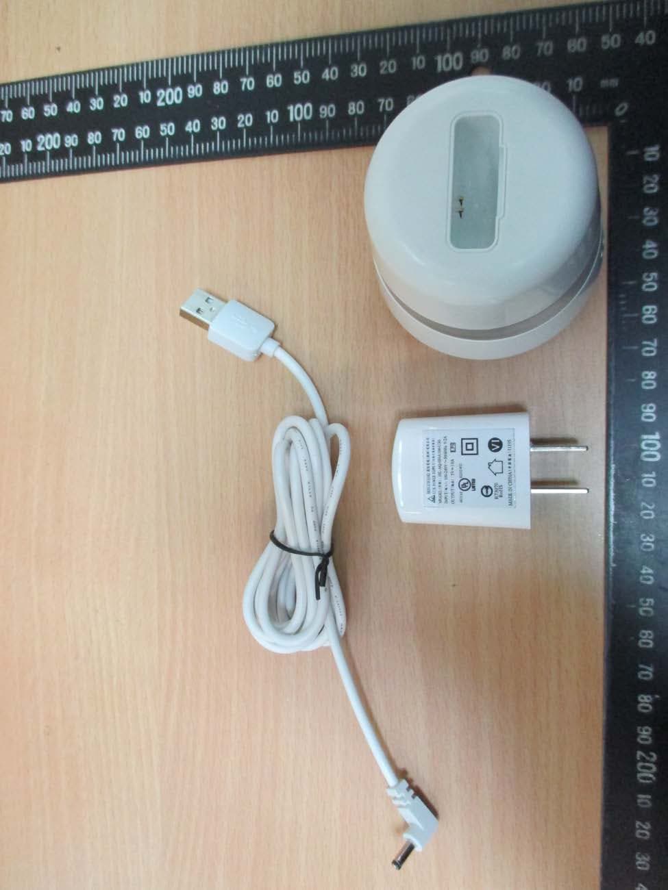
External Photos
Registration number: W6M21912-19560-C-1 FCC ID: WCO-DS101 External Photos Worldwide Testing Services(Taiwan) Co., Ltd. Appendix Page 1 of 17 Registration number: W6M21912-19560-C-1 FCC ID: WCO-DS101 Worldwide Testing Services(Taiwan) Co., Ltd. Appendix Page 2 of 17 Registration number: W6M21912-19560-C-1 FCC ID: WCO-DS101 Worldwide Testing Services(Taiwan) Co., Ltd. Appendix Page 3 of 17 Registration number: W6M21912-19560-C-1 FCC ID: WCO-DS101 Worldwide Testing Services(Taiwan) Co., Ltd. Appendix Page 4 of 17 Registration number: W6M21912-19560-C-1 FCC ID: WCO-DS101 Worldwide Testing Services(Taiwan) Co., Ltd. Appendix Page 5 of 17 Registration number: W6M21912-19560-C-1 FCC ID: WCO-DS101 Worldwide Testing Services(Taiwan) Co., Ltd. Appendix Page 6 of 17 Registration number: W6M21912-19560-C-1 FCC ID: WCO-DS101 Worldwide Testing Services(Taiwan) Co., Ltd. Appendix Page 7 of 17 Registration number: W6M21912-19560-C-1 FCC ID: WCO-DS101 Worldwide Testing Services(Taiwan) Co., Ltd. Appendix Page 8 of 17
Internal Photos
Registration number: W6M21912-19560-C-1 FCC ID: WCO-DS101 Internal Photos Worldwide Testing Services(Taiwan) Co., Ltd. Appendix Page 9 of 17 Registration number: W6M21912-19560-C-1 FCC ID: WCO-DS101 Worldwide Testing Services(Taiwan) Co., Ltd. Appendix Page 10 of 17 Registration number: W6M21912-19560-C-1 FCC ID: WCO-DS101 Worldwide Testing Services(Taiwan) Co., Ltd. Appendix Page 11 of 17 Registration number: W6M21912-19560-C-1 FCC ID: WCO-DS101 Worldwide Testing Services(Taiwan) Co., Ltd. Appendix Page 12 of 17 Registration number: W6M21912-19560-C-1 FCC ID: WCO-DS101 Worldwide Testing Services(Taiwan) Co., Ltd. Appendix Page 13 of 17 Registration number: W6M21912-19560-C-1 FCC ID: WCO-DS101 Worldwide Testing Services(Taiwan) Co., Ltd. Appendix Page 14 of 17
RF Exposure Info
Registration number: W6M21912-19560-C-1 FCC ID: WCO-DS101 3.2 Equivalent Isotropic Radiated Power (EIRP) FCC Rule: 15.247(b)(3) BT4.0 EIRP = max. conducted output power + antenna gain EIRP =3.76 dBm + (2.71 dBi [antenna gain claimed by manufacturer]) = 6.47 dBm = 4.4361 mW BT5.0 EIRP = max. conducted output power + antenna gain EIRP =3.69 dBm + (2.71 dBi [antenna gain claimed by manufacturer]) = 6.4 dBm = 4.3652 mW 3.3 Exemption Limits for Routine Evaluation according to 47 CFR FCC Part 2 Subpart J, section 2.1091 FCC OET Bulletin 65 Edition 97.01 determines the equations for predicting RF fields and applicable limits. The prediction for power density in the far-field but will over-predict power density in the near field, where it could be used for walking a “worst case” or conservative prediction. Systems operating under the provisions of this section shall be operated in a manner that ensures that the public is not exposed to radio frequency energy levels in excess limit for maximum permissible exposure. In accordance with 47 CFR FCC Part 2 Subpart J, section 2.1091 this device has been defined as a mobile device whereby a distance of 20 cm normally can be maintained between the user and the device. MPE Calculation Method Worldwide Testing Services(Taiwan) Co., Ltd. Page 17 of 37 Registration number: W6M21912-19560-C-1 FCC ID: WCO-DS101 E = Electric field (V/m) P = output power (W) G = EUT Antenna numeric gain (numeric) d = Separation distance between radiator and human body (m) The formula can be changed to mW/cm 2 . Established separation distance is 20 cm. Operating frequency band: 2402-2480 MHz The product meets RF exposure requirement. Because the power density of 0.0009 mW/cm 2 at 2480 MHz is below the power density limit of 1 mW/cm 2 . Worldwide Testing Services(Taiwan) Co., Ltd. Page 18 of 37
Test Report
of Applicant: Microtips Technology Inc. Address: 12F, No.31, Lane 169, Kang-Ning St., Hsi-Chih District, New Taipei City 221, Taiwan, R.O.C Tested and Prepared by Worldwide Testing Services (Taiwan) Co., Ltd. FCC Registration No.: TW1477, TW0020, TW1072 Industry Canada filed test laboratory Reg. No. 20037 A2LA Accredited No.: 2732.01 Report No.: W6M21912-19560-C-1 6F, NO. 58, LANE 188, RUEY-KUANG RD., NEIHU TAIPEI 114, TAIWAN, R.O.C. TEL: 886-2-66068877 FAX: 886-2-66068879 E- mail: [email protected] FCC PART 15 SUBPART C TEST REPORT for Intelligent Diaper Dock Station Model No.: DS-101 FCC ID: WCO-DS101 Registration number: W6M21912-19560-C-1 FCC ID: WCO-DS101 TABLE OF CONTENTS 1 GENERAL INFORMATION ......................................................................................................................................... 2 1.1 NOTES ...................................................................................................................................................................... 2 1.2 TESTING LABORATORY ............................................................................................................................................. 3 1.2.1 Location .............................................................................................................................................................. 3 1.2.2 Details of accreditation status ............................................................................................................................ 3 1.3 DETAILS OF APPROVAL HOLDER ............................................................................................................................... 3 1.4 APPLICATION DETAILS .............................................................................................................................................. 4 1.5 GENERAL INFORMATION OF TEST ITEM ..................................................................................................................... 4 1.6 TEST STANDARDS ..................................................................................................................................................... 5 2 TECHNICAL TEST ........................................................................................................................................................ 6 2.1 SUMMARY OF TEST RESULTS ..................................................................................................................................... 6 2.2 TEST ENVIRONMENT ................................................................................................................................................. 6 2.3 TEST EQUIPMENT LIST .............................................................................................................................................. 7 2.4 GENERAL TEST PROCEDURE ................................................................................................................................... 10 3 TEST RESULTS (ENCLOSURE) ............................................................................................................................... 12 3.1 PEAK OUTPUT POWER (TRANSMITTER) ................................................................................................................... 13 3.2 EQUIVALENT ISOTROPIC RADIATED POWER (EIRP) ............................................................................................... 17 3.3 EXEMPTION LIMITS FOR ROUTINE EVALUATION ACCORDING TO ............................................................................ 17 47 CFR FCC PART 2 SUBPART J, SECTION 2.1091 ................................................................................................. 17 3.4 TRANSMITTER RADIATED EMISSIONS IN RESTRICTED BANDS ................................................................................ 19 3.5 SPURIOUS EMISSIONS (TX) ...................................................................................................................................... 20 3.6 RADIATED EMISSION ON THE BAND EDGE ............................................................................................................... 22 3.7 MINIMUM 6 DB BANDWIDTH .................................................................................................................................. 25 3.8 PEAK POWER SPECTRAL DENSITY .......................................................................................................................... 29 3.9 RADIATED EMISSION FROM RECEIVER PART .......................................................................................................... 33 3.10 POWER LINE CONDUCTED EMISSION ...................................................................................................................... 34 APPENDIX.............................................................................................................35 Worldwide Testing Services(Taiwan) Co., Ltd. Page 1 of 37 Registration number: W6M21912-19560-C-1 FCC ID: WCO-DS101 1 General Information 1.1 Notes The purpose of conformity testing is to increase the probability of adherence to the essential requirements or conformity specifications, as appropriate. The complexity of the technical specifications, however, means that full and thorough testing is impractical for both technical and economic reasons. Furthermore, there is no guarantee that a test sample which has passed all the relevant tests conforms to a specification. Neither is there any guarantee that such a test sample will interwork with other genuinely open systems. The existence of the tests nevertheless provides the confidence that the test sample possesses the qualities as maintained and that is performance generally conforms to representative cases of communications equipment. The test results of this test report relate exclusively to the item tested as specified in 1.5. The test report may only be re…
Text truncated - open the document above for the full version.
Test Setup Photos
Registration number: W6M21912-19560-C-1 FCC ID: WCO-DS101 Set Up Photo of Radiated Emission Below 1 GHz Worldwide Testing Services(Taiwan) Co., Ltd. Appendix Page 15 of 17 Registration number: W6M21912-19560-C-1 FCC ID: WCO-DS101 Above 1 GHz Worldwide Testing Services(Taiwan) Co., Ltd. Appendix Page 16 of 17 Registration number: W6M21912-19560-C-1 FCC ID: WCO-DS101 Set Up Photo of Conducted Emission Worldwide Testing Services(Taiwan) Co., Ltd. Appendix Page 17 of 17
Contact Information
Applicant
Thomas CHOU(Product Manager)
Technical Contact
Worldwide Testing Services (Taiwan) Co., Ltd.Danny Sung
[email protected]886-2-6606-8877
6F., No.58, Lane 188, Ruey Kuand Rd., · Taiwan
Non-Technical Contact
Worldwide Testing Services (Taiwan) Co., Ltd.Rita Lin
[email protected]886-2-6606-8877
Test Firm
Worldwide Testing Services (Taiwan) Co., Ltd.Rex Kao
Technical Specifications
| # | Rule Parts | Frequency Range | Power Output |
|---|---|---|---|
| 1 | 15C | 2.40 GHz - 2.48 GHz | 2.40 mW |
Other Applications from Microtips Technology Inc.
WCO-GW101
Mar 10, 2020Intelligent Diaper Gateway
Equipment Class
DTS - Digital Transmission System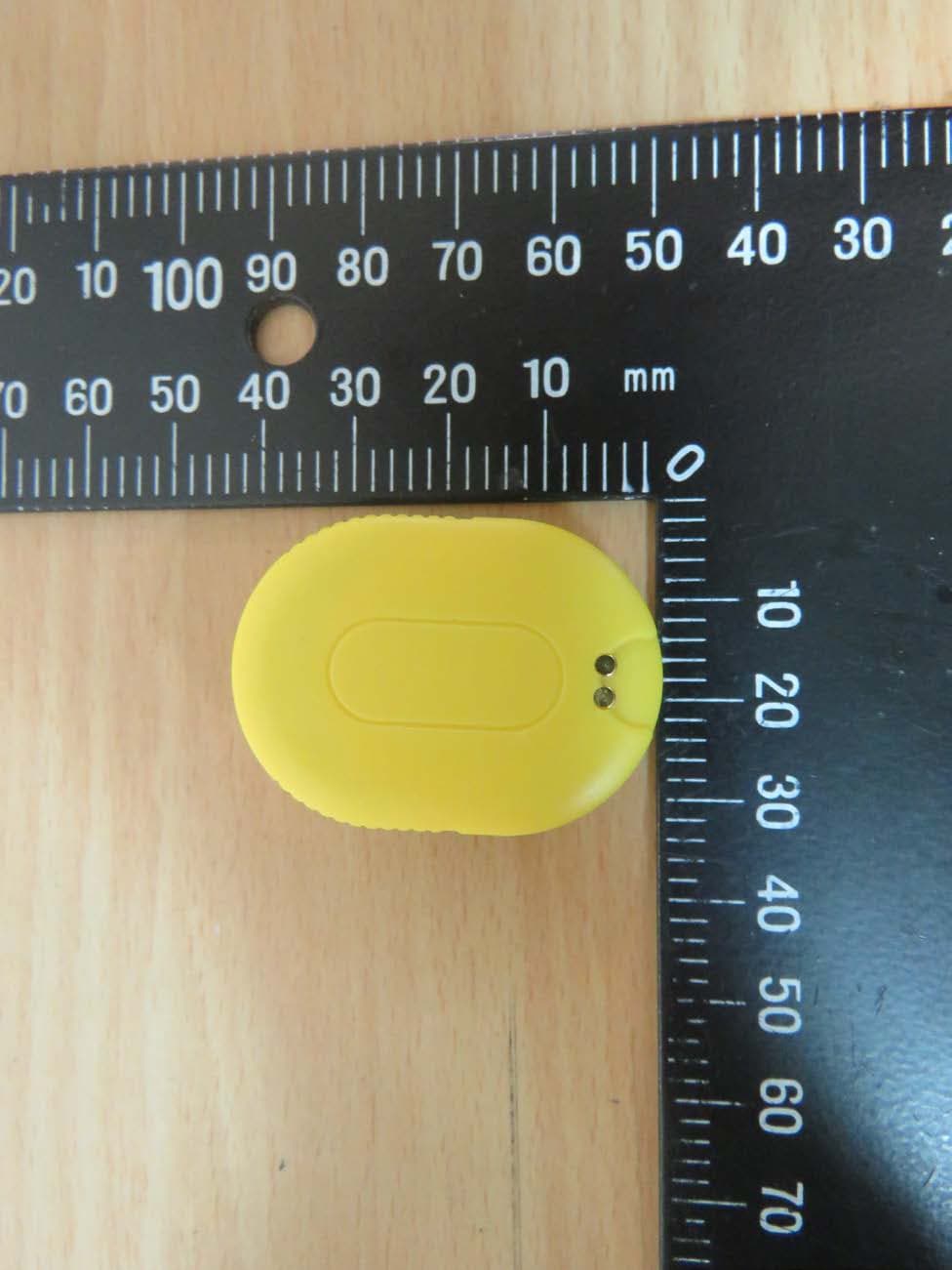
WCO-SG101
Mar 03, 2020Intelligent Diaper Sensor for Gateway
Equipment Class
DTS - Digital Transmission System