WFZSCND503H1231CS-II-5M-3.0
EU3C COMPANY LIMITED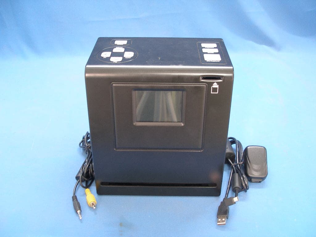
Click to zoom
Application Details
- Equipment Class
- JBP - Part 15 Class B Computing Device Peripheral
- Date of Grant
- Mar 28, 2011
- Application Purpose
- Original Equipment
- Date of Application
- Mar 28, 2011
- Equipment Note
- CS-II-5M-3.0
- Company
- EU3C COMPANY LIMITED
- Country
- Hong Kong
Documents & Files
Document Text
Text extracted from the exhibit documents filed with the FCC. Open a document above to read the original.
Users Manual
Combo Scanner II Combo Scanner II‐5M‐3.0 User Manual Version 1.02 January 2011 Index I. Unpack Combo Scanner II.....................................................2 II. Install film into the film holder..............................................3 III. Quick Start.........................................................................6 IV. Operation Guide..............................................................14 V. Specification....................................................................33 ‐1‐ I. Unpack Combo Scanner II Combo Scanner II Negative Film Holder Photo/Business Card Holder Note We strongly suggest using a clean, dry, non-alcohol cotton swab to clean the glass surface on the back-light holder and the business card fixture periodically to produce a clear image. Make sure all negative films, slide films, cover trays and photos are free of dust and dirt before inserting into the Combo Scanner as this may affect the image quality when scanning. When cleaning films, please use a professionally recommended purger from a photo store to avoid damaging old or precious films. ‐2‐ USB/Video Cable Power Core& Cable User Manual Slide Film Holder Backlight Holder Clean Brush Business Card Fixture II. Install film into the film holder ● Install slide film into the holder entitled “Slides Only” 1. Open the slide holder as illustrated ● Install Negative Film into holder entitled “Negative Film Only” 1. Open the film holder as illustrated 2. Install film into negative film slot 3. Close the film holder ‐3‐ 2. Place slide in recessed slot in holder 3. Close the slideholder Note To avoid mirror image, follow the serial numbers (from left to right) on top of film when install negative film into holder If the image is upside down [Figure 2.2], the image can be corrected by pressing Down/Flip button before capturing [Figure 2.3]. Alternative, enter the playback mode and press Mode button to select Flip function [Figure 2.4] ‐4‐ Figure 2.1 Figure 2.2 ● Press hard key on top of device in live view [Figure 2.3] ● Press Playback button Mode/Setting to select Flip function (Refer to P.25) [Figure 2.4] ‐5‐ Down/Flip button (Flip hard key) Flip Playback button Photo/Business Card slot III. Quick Start ‐6‐ Up/Mirror OK/Capture Down/Flip Power button Power status LED Film/Slide slot Slot for Backlight holder USB Port (For data only) TV out jack Power core port Playback Mode/Setting Left/EV Right/Color SD card slot How to use Combo Scanner II Scanning Film/Slide 1. Put Film into Film holder, and Insert the film holder into the right side of the unit. 2. Insert the back light holder at the rear side of the unit. 3. Plug in power cable to the power port on the unit and one end to the power outlet (Figure 3.1). ‐7‐ Figure 3.1 4. Press Power button to power on the unit. Enter media type menu to select the correct media for scanning. (Refer to P.29) 5. Press OK/Capture button to capture the image. 6. Press on Playback button to playback the saved images. ‐8‐ Power button OK/Capture button Playback button Media Type 7. After capturing, take out the SD card which stored the saved images. 8. Alternative to 7, saved picture can be read directly, without taking out the SD card, from PC by entering MSDC mode. (Refer to P.31) ‐9‐ Scanning Photo 1. Remove the film/slide holder as well as the back light holder from the unit if either one is attached. 2. Open the photo holder frame as illustrated, place the photo on the base of the photo holder and close the photo holder frame. ‐10‐ Remove film/slide holder by exiting the sliding to the left hand side. Remove backlight holder by pressing down the handle and pull it out. 3. Insert the photo holder into the photo slot of the unit. 4. Enter Media Type Mode to select the correct media for scanning. (Refer to P.29) 5. Press OK/Capture button to capture the image. ‐11‐ OK/Capture button Media Type Scanning Business Card 1. Follow step 1 from scanning photo to remove the film/slide holder as well as the back light holder in the previous pages. 2. Open the photo holder frame and place the business card on the base of the photo holder following the engraved guide line. 3. Put the business card fixture on the top of photo holder. ‐12‐ 4. Insert the photo holder with business card fixture into the photo slot of the unit. 5. Enter media type menu to select the correct media for scanning. (Refer to P.29) 6. Press OK/Capture button to capture the image. ‐13‐ OK/Capture button Media Type IV. Operation Guide ‐14‐ CaptureMode SettingMode Playback Mode Live View Mode 1. Live View Mode After a quick display of welcome page, system will enter the Live View mode. A flashing red dot appears on the top left hand corner indicating the state in Live View. (Note: select correct media type (Refer to P.29) before capturing. By default the setting is at Negative Film. Unit will reset back to the default setting after power off) 1.1 Mirror (Hard Key) ● Press Up/Mirror button to turn the image left to right, press again vice versa ‐15‐ Up/Mirror Up/Mirror button OK/Capture Live View indicator (flashing at 0.5sec rate) Save & Exit 1.2 Flip (Hard Key) ● Press Down/Flip button to turn the image upside down, press again vice versa 1.3 EV (Hard Key) ● Press Left/EV button to enter EV(Brightness) control ‐16‐ Down/Flip button Down/Flip OK/Capture Save & Exit Left/EV OK/Capture Save & Exit Up/+ Down/‐ ● Press Up/+ button to increase exposure(brightness) with ranges of ‐3 to 3 ● Press Down/‐ button to decrease exposure(brightness) with ranges of ‐3 to 3 1.4 Color (Hard Key) ● Press Right/Color button to enter color control ‐17‐ Up /+ button Down/- button Right/Color OK/Capture Save & Exit Up/+ Down/‐ ● Press Up/+ button to increase Color with ranges of ‐3 to 3 ● Press Down/‐ button to decrease Color with ranges of ‐3 to 3 ● Press arrow hard key Left and Right to move between R, G, B ‐18‐ Up /+ button Down /- button Left/Go Previous Right/Go Next 2. Capture Mode Once user presses the OK/Capt…
Text truncated - open the document above for the full version.
Block Diagram
Sensor DDR SDRAMHY HY5DU561622CTP NAND FLASH HY 27US08561A KEY POWER TFT LCD panel SD CARD TV_OUT PORT USB PORT 12MHZ 32.768KHZ OV5633 GP or Tpo 3.0'' TFT BL LightBar
External Photos
EUT EXTERIOR PHOTO Applicant: EU3C Company Limited FCC ID: WFZSCND503H1231
ID Label/Location Info
FCC ID: WFZSCND503H1231 This device complies with Part 15 of the FCC Rules. Operation is subject to the following two conditions: (1) this device may not cause harmful interference, and (2) this device must accept any interference received, including interference that may cause undesired operation.
ID Label/Location Info
Label Location EUT Bottom View/Proposed FCC ID LABEL location
Internal Photos
EUT INSIDE PHOTO Applicant: EU3C Company Limited FCC ID: WFZSCND503H1231
Operational Description
一.Block Diagram 二.Machines working principium as follow up: 1. One end of the corresponding computer USB cable port, the other end of the scanner (the computer must be turned on) 2. Press POWER button to open the DSP instructions, DSP power system starts after receiving the instruction. DSP initialization is complete, the system default according to NAND FLASH to run inside and get the boot welcome screen TFT LCD display, the initial of SENSOR, complete, enter the scan mode. 3. Fitted to scan FILM, backlight light emitted by the lens through the imaging FILM, FILM in the SENSOR the image on the display. SENSOR to optical signals into electrical signals sent to DSP, DSP on into the Signal into the handling, processing, temporary storage in DDR SDRAM, the same time to send TFT LCD display. 4. Operator prompts according to the image on the LCD, the keyboard to control the DSP to do the appropriate treatment (eg: scan, delete, etc.). 5. Users to save scanned images under the NAND FLASH (SD card when inserted into the SD card first) 6. When using the TV cable are connected to a TV PORT, it will close the LCD display, the TV display. 7. They can enter the system with a set put the scanner into USB mode, then USB will stop scanning, and computer on-line access to MSDC mode. 8. Again press POWER button, DSP instructions received, it will turn off the power system, enter the shutdown state.
Schematics
55 44 33 22 11 D D C C B B A A FCD FEXTBSY CMD PWR ON/OFF ADC1 ADC1 DA1 DA2 DA0FCLK FCD PWR ON/OFF FCLK CMD DA2 FEXTBSY ADC1 DA3DA1DA0 DA3 DGND MGND MGND MGND MGND DGND CD3V3 CD3V3 CD3V3 MGND Size Document Number Rev Date: Sheet of DESIGN CHECK APPROVE Fenggang Zhen, Dongguan City,Guangdong Province7F, Fengwei Tower,Zhengtong Rd NO.13 CS-II SD_Key_B 1.4 A3 11 Thursday, May 27, 2010 Size Document Number Rev Date: Sheet of DESIGN CHECK APPROVE Fenggang Zhen, Dongguan City,Guangdong Province7F, Fengwei Tower,Zhengtong Rd NO.13 CS-II SD_Key_B 1.4 A3 11 Thursday, May 27, 2010 Size Document Number Rev Date: Sheet of DESIGN CHECK APPROVE Fenggang Zhen, Dongguan City,Guangdong Province7F, Fengwei Tower,Zhengtong Rd NO.13 CS-II SD_Key_B 1.4 A3 11 Thursday, May 27, 2010 S1 KEY Set S1 KEY Set 12 S2 KEY Mode S2 KEY Mode 12 R24.7KR24.7K S3 KEY OK S3 KEY OK 12 R315KR315K R9 27R R0603 R9 27R R0603 R10 300R R0603 R10 300R R0603 R633KR0603R633KR0603 R11 300R R0603 R11 300R R0603 R7 33K R0603R7 33K R0603 R8 27R R0603 R8 27R R0603 R12 27R R0603 R12 27R R0603 R13 27R R0603 R13 27R R0603 R410k R\SMT8 R410k R\SMT8 1 3 5 78 6 4 2 J1 KEY CON3/DIP/1.25/B J1 KEY CON3/DIP/1.25/B 123 R12K4R12K4 R5 33K R0603R5 33K R0603 J2 F03-0647-00001SD-CARD-COMBO J2 F03-0647-00001SD-CARD-COMBO DAT3 1 CMD 2 VSS 3 VDD 4 SCLK 5 VSS2 6 DAT0 7 DAT1 8 GND 12 DAT2 9 CD 10 WP 11 J3 CON16 CONSMT16P J3 CON16 CONSMT16P 123456789 10111213141516 C10.1uFC0603C10.1uFC0603 55 44 33 22 11 D D C C B B A A ADC1 PWR ON/OFF ADC1 PWR ON/OFF MGND MGND MGND MGND MGND MGND Size Document Number Rev Date: Sheet of DESIGN CHECK APPROVE Fenggang Zhen, Dongguan City,Guangdong Province7F, Fengwei Tower,Zhengtong Rd NO.13 COMBO_Five Key_B v1.0 A 67 Size Document Number Rev Date: Sheet of DESIGN CHECK APPROVE Fenggang Zhen, Dongguan City,Guangdong Province7F, Fengwei Tower,Zhengtong Rd NO.13 COMBO_Five Key_B v1.0 A 67 Size Document Number Rev Date: Sheet of DESIGN CHECK APPROVE Fenggang Zhen, Dongguan City,Guangdong Province7F, Fengwei Tower,Zhengtong Rd NO.13 COMBO_Five Key_B v1.0 A 67 R327KR327K R210KR210K S3 KEY LEFT S3 KEY LEFT 12 S1 KEY DOWN S1 KEY DOWN 12 S4 KEY RIGHT S4 KEY RIGHT 12 R16K8R16K8 J1 KEY CON3/DIP/1.25/B J1 KEY CON3/DIP/1.25/B 123 R447KR447K S2 KEY UP S2 KEY UP 12 S5 SW4 S5 SW4 1 2 ABCD DCBA Title Number Revision Size A4 Date: 24-Jan-2011 Sheet of File: C:\Do cu men ts and Set ti ngs \Ad mi ni strat or\ 桌面 \pro telw orkfil e\CS-II.dd b Drawn By: EU3C COMPANY LIMITED LED BAR 1.0 1 of 1 Vout 1 Gnd 2 EN 3 Vin 5 CN 4 CP 6 U1 RT9361B 21 Fixed 3 Fixed 4 J2CON2 21 Fixed 3 Fixed 4 J3CON2 LED4 LED3 LED2 LED1 R2 NC R1100ohm/0603 C1 1uF/0603 C210uF/1206 C310uF/1206 LED8 LED7 LED6 LED5 Go to J5 on USB+PWR+TV board J2 connected to J3 Note: The schematic drawing invovle 2 pcs LED-BAR PCB 5V EN 3 Gnd 2 Vin 1 Fixed 5 Fixed 4 J1CON3 TP1 5 4 3 2 1 DCBA A Size Document Number Rev Date: Sheet of DESIGN CHECK APPROVE Fenggang Zhen, Dongguan City,Guangdong Province7F, Fengwei Tower,Zhengtong Rd NO.13 <Doc> V0A A4 17 Friday, November 05, 2010 Size Document Number Rev Date: Sheet of DESIGN CHECK APPROVE Fenggang Zhen, Dongguan City,Guangdong Province7F, Fengwei Tower,Zhengtong Rd NO.13 <Doc> V0A A4 17 Friday, November 05, 2010 Size Document Number Rev Date: Sheet of DESIGN CHECK APPROVE Fenggang Zhen, Dongguan City,Guangdong Province7F, Fengwei Tower,Zhengtong Rd NO.13 <Doc> V0A A4 17 Friday, November 05, 2010 TIME EDITER Schematic Revision REVREVREV REVREV REVISION HISTORY OF REV HISHISHISHIS OA HISHISHISHISHISHISHISHISHISHISHISHIS TIME1TIME2TIME3 TIM0 NAME0NAME1NAME2 NAME3 TIME EDITER Schematic Revision REVREVREV REVREV REVISION HISTORY OF REV HISHISHISHIS OA HISHISHISHISHISHISHISHISHISHISHISHIS TIME1TIME2TIME3 TIM0 NAME0NAME1NAME2 NAME3 TIME EDITER Schematic Revision REVREVREV REVREV REVISION HISTORY OF REV HISHISHISHIS OA HISHISHISHISHISHISHISHISHISHISHISHIS TIME1TIME2TIME3 TIM0 NAME0NAME1NAME2 NAME3 55 44 33 22 11 D D C C B B A A FOEN FA1 CCLK RAM_DAT15 RAM_CLK DVCNTL0 FWRN DVCNTL[0..6] RAM_UDMRAM_VREF RAM_ADD12 FA0 RAM_DAT2 RAM_ADD8 RAM_RASN RAM_DAT13RAM_DAT1 FA23 RAM_DAT0RAM_DAT14 HIS RAM_ADD5 RAM_CKEN RAM_ADD3 FCD1N RAM_ADD2 VCM RAM_DAT9 RAM_BA1 DVCNTL3 FRESBSYN FA14 RAM_CSN DVCNTL1 FA22 RAM_DAT8 USBVBUS VCLKO PWRENBPWRON0 DVCNTL2 RAM_DAT7 RAM_DAT[0..15] RAM_BA0 RAM_LDQS CCLKOUT FA21 RAM_BA[0..1] FA13 VCLKO RAM_LDM FA15 VCLKI AREFRAM_WEN RAM_DAT6 FA19 DVCLK PWM3 FA16 RAM_ADD10 FA18 RAM_UDQS VIS RAM_ADD1 DVCNTL5 RSET RAM_ADD9 FA17 FA20 RAM_DAT10 EJTCK USBDN RAM_DAT3 RAM_ADD11 PDETECT DVCNTL4 RAM_DAT5 USBDP RAM_ADD7 RAM_DAT4 FA20 RAM_DAT12 RAM_ADD6 RAM_DAT11 RAM_ADD4 PWM1 RAM_ADD0 RAM_CASN RAM_ADD[0..12] RAM_CLKN USBRSET FA22 RESET_N VID5VID7VID3VID2VID1VID0VID9VID6 VID[0..9] VID4VID8 FRESCEN FEXTBSYN PDETECT VDD_PWRPWRON1PWRON2 FA13DVDAT0 DVDAT[0..7] DVDAT2 DVDAT1 DVDAT3 DVDAT6 DVDAT5 DVDAT7 DVDAT4 DVDAT0 DVDAT2DVDAT4DVDAT1DVDAT3FA14 SDASCL RTCXIRTCXO RTCXIRTCXO TXDRXD FA12FA5FA7FCD1NFEXTBSYNFA4 FA5 FA4 FA12 VCLKI GND FA16FA19FA17FA18FA15 FD3 FD7 FA7 FD2 FD0 FA6 FD5 FD[0..7] FD6 FD1 FD4 FA6 FA21FA23 PWM0 DVCNTL6 PWM3 PWM1 VDD_2V5 VDD_2V5 VDD_3V3 VDD_3V3VDD_3V3 VDD_1V8 VDD_3V3 VDD_1V8 VDD_1V8VDD_3V3 VDDPWR VDD_3V3 VDD_3V3 GND VDD_3V3 VDD_3V3 VDD_3V3 VDDPWR VDD_3V3 VDD_3V3 VIN VDD_3V3 RAM_VREF 3 RAM_DAT[0..15] 3RAM_ADD[0..12] 3RAM_BA[0..1] 3 RAM_CASN 3 RAM_RASN 3 RAM_CLK 3 RAM_CLKN 3 RAM_LDM 3 RAM_UDM 3 RAM_LDQS 3 RAM_UDQS 3 RAM_CSN 3 RAM_WEN 3 RAM_CKEN 3 FD[0..7] 3 CCLKOUT 7 CCLK 7 SCL 7 SDA 7 HIS 7 VIS 7 VID[0..9] 7 FRESBSYN 3 FA1 3 FA0 3 DVCLK 4 DVCNTL[0..6] 4 DVDAT[0..7] 4 FWRN 3 FOEN 3 FRESCEN 3 PWRENB 5 USBDN 6 USBDP 6 FCLK 6 DA1 6 DA2 6 CMD 6 FEXTBSY 6 FCD 6 DA0 6 PWRON0 5 RESET_N 3,5 DA3 6 TV/TFTDETECT-IN 6 CVBSOUT 6 VCM_EN 7 BL/CNL6 GPADC1 6 BLC 6 VCM_SDA 7 VCM_SCL 7 WDI 5 Size Document Number Rev Date: Sheet of DESIGN CHECK APPROVE Fenggang Zhen, Dongguan City,Guangdong Province7F, Fengwei Tower,Zhengtong Rd NO.13 COMBO_COACH9E v1.3 Custom 27 Tuesday, November 09, 2010 Size Document Number Rev Date: Sheet of DESIGN CHECK APPROVE Fenggang Zhen, Donggua…
Text truncated - open the document above for the full version.
Test Report
Page 1of 24 Rev. 00 FCC CLASS B COMPLIANCE REPORT for Electromagnetic Emissions of CS-II-5M-3.0 Trade Name : N/A Model Number : SCND503H1231 Serial Number : N/A Report Number : ST1103009F FCC ID :WFZSCND503H1231 Date : March 23, 2011 Prepared for : EU3C Company Limited Unit 7, 8/F., Austin Tower, 22-26 Austin Avenue, Tsim Sha Tsui, Kowloon, Hong Kong Prepared by : SINTEK LABORATORY CO., LTD. d.b.a. SINTEK LABORATORY CO., LTD. NO.7, XINSHIDAI INDUSTRIAL,GUANTIAN VILLAGE, SHIYAN TOWN, BAO’AN DISTRICT, SHENZHEN, GUANGDONG, P.R.C TEL:86-755-27604866 FAX:86-755-27608359 Page2 Rev. 00 TABLE OF CONTENTS DESCRIPTION PAGE VERIFICATION OF COMPLIANCE 3 SYSTEM DESCRIPTION 4 PRODUCT INFORMATION 5 SUPPORT EQUIPMENT 6 SECTION 1 FCC(LINE CONDUCTED & RADIATED EMISSION) 7 MEASUREMENT PROCEDURE & LIMIT (LINE CONDUCTED EMISSION TEST) 7 MEASUREMENT PROCEDURE & LIMIT (RADIATED EMISSION TEST) 10 SUMMARY DATA 13 TEST FACILITY 16 TEST EQUIPMENT LIST 17 BLOCK DIAGRAM OF TEST SETUP 18 APPENDIX 1 PHOTOGRAPHS (TEST SETUP OF LINE CONDUCTED EMISSION) 19 APPENDIX 2 PHOTOGRAPHS (TEST SETUP OF RADIATED EMISSION) 21 APPENDIX 3 PHOTOS OF EUT 23 Page3 Rev. 00 VERIFICATION OF COMPLIANCE Equipment Under Test: CS-II-5M-3.0 Trade Name: N/A Model Number: SCND503H1231 Serial Number: N/A Applicant: EU3C Company Limited Unit 7, 8/F., Austin Tower, 22-26 Austin Avenue, Tsim Sha Tsui, Kowloon, Hong Kong Manufacturer: EU3C Company Limited Unit 7, 8/F., Austin Tower, 22-26 Austin Avenue, Tsim Sha Tsui, Kowloon, Hong Kong Type of Test: FCC Class B Measurement Procedure: ANSI C63.4: 2001 File Number: FCC ID: ST1103009F WFZSCND503H1231 Date of test: March 15-23, 2011 Deviation: None Condition of Test Sample: Normal The above equipment was tested by SinTek Laboratory Co.,Ltd. for compliance with the requirements set forth in the FCC Rules and Regulations Part 15, Subpart B and the measurement procedure according to ANSI C63.4. This said equipment in the configuration described in this report shows the maximum emission levels emanating from equipment are within the compliance requirements. The test results of this report relate only to the tested sample identified in this report. Approved by Authorized Signatory: Page4 Rev. 00 SYSTEM DESCRIPTION EUT Test Program: 1. Set up EUT with the auxiliary equipment. 2. Let the EUT work in test mode and measure it. Page5 Rev. 00 PRODUCT INFORMATION Housing Type: Plastic EUT Power Rating: DC 5V Power during Test: DC 5V by Adapter USB Cable: Non-shielded Detachable Ferrite cor 1.2m TV Non-shielded Detachable Ferrite cor 3m Power supply: Input:100-240V Output:5.0V1.0A I/O Port of EUT: I/O Port Type Q’TY Tested with USB 1 1 TV 1 1 DC IN 1 1 Difference between model numbers as below: Model Number Trade Name N/A N/A Page6 Rev. 00 SUPPORT EQUIPMENT No. Equipment Model # Serial # Trade Name Data Cable Power Cord 1. TV ALJ-777 N/A Anlijia Non-shielde d1.0m Non-shielded 1.5m **Note: All the above equipment/cables were placed in worse case positions to maximize emission signals during emission test. Grounding: Grounding was in accordance with the manufacturer’s requirements and conditions for the intended use. Page7 Rev. 00 SECTION 1 FCC (LINE CONDUCTED AND RADIATED EMISSION) MEASUREMENT PROCEDURE (PRELIMINARY LINE CONDUCTED EMISSION TEST) 1) The equipment was set up as per the test configuration to simulate typical actual usage per the user’s manual. When the EUT is a tabletop system, a wooden table with a height of 0.8 meters is used and is placed on the ground plane as per ANSI C63.4 (see Test Facility for the dimensions of the ground plane used). When the EUT is a floor-standing equipment, it is placed on the ground plane which has a 3-12 mm non-conductive covering to insulate the EUT from the ground plane. 2) Support equipment, if needed, was placed as per ANSI C63.4. 3) All I/O cables were positioned to simulate typical actual usage as per ANSI C63.4. 4) The EUT received DC 5V by Adapter, and Adapter received AC120V/60Hz power through a Line Impedance Stabilization Network (LISN) which supplied power source and was grounded to the ground plane 5) All support equipments received 120V/60Hz power from a second LISN, if any. 6) The EUT test program was started. Emissions were measured on each current carrying line of the EUT using a spectrum Analyzer / Receiver connected to the LISN powering the EUT. The LISN has two monitoring points: Line 1 (Hot Side) and Line 2 (Neutral Side). Two scans were taken: one with Line 1 connected to Analyzer / Receiver and Line 2 connected to a 50 ohm load; the second scan had Line 1 connected to a 50 ohm load and Line 2 connected to the Analyzer / Receiver. 7) Analyzer / Receiver scanned from 150kHz to 30MHz for emissions in each of the test modes. 8) During the above scans, the emissions were maximized by cable manipulation. 9) The following test mode(s) were scanned during the preliminary test: Preliminary Conducted Emission Test Frequency Range Investigated 150KHz TO 30 MHz Mode of operation Date Data Report No. Worst Mode TV 03/16/2011 SCND503H1231 _0(L,N) SD 03/16/2011 SCND503H1231 _1(L,N) PLAY 03/16/2011 SCND503H1231 _2(L,N) Then, the EUT configuration and cable configuration of the above highest emission level were recorded for reference of final testing. Page8 Rev. 00 MEASUREMENT PROCEDURE (FINAL LINE CONDUCTED EMISSION TEST) 1) EUT and support equipment was set up on the test bench as per step 9 of the preliminary test. 2) A scan was taken on both power lines, Line 1 and Line 2, recording at least the six highest emissions. Emission frequency and amplitude were recorded into a computer in which correction factors were used to calculate the emission level and compare reading to the applicable limit. If EUT emission level was less –2dB to the A.V. limit in Peak mode, then the emission signal was re-checked using an Average detector. 3) The test data of the worst case condition(s) was reported on the Summary Data page. Data Sample: Freq. MHz Peak Raw dBuV Q.P. Raw dBuV Ave…
Text truncated - open the document above for the full version.
Test Setup Photos
TEST SETUP PHOTO Applicant: EU3C Company Limited FCC ID: WFZSCND503H1231 LINE CONDUCTED EMISSION TEST RADIATED EMISSION TEST
Contact Information
Applicant
LETTY LEE(SENIOR INTERNAL CONTROLLER)
Test Firm
SinTek Laboratory Co., Ltd.Eric Lin
Technical Specifications
| # | Rule Parts | Frequency Range | Power Output |
|---|---|---|---|
| 1 | 15B | - | - |
Other Applications from EU3C COMPANY LIMITED

WFZSCND502B1232
Apr 12, 2011PART 15 CLASS B COMPUTING PERIPHERAL
Equipment Class
JBP - Part 15 Class B Computing Device Peripheral
WFZSCND522A1231
Mar 28, 2011FS-I-5M-ND
Equipment Class
JBP - Part 15 Class B Computing Device Peripheral
WFZBCS200211011
Mar 24, 2011Businesscardscanner Foldable
Equipment Class
JBP - Part 15 Class B Computing Device Peripheral
WFZSCND502E1234
Mar 22, 2011PART 15 CLASS B COMPUTING PERIPHERAL
Equipment Class
JBP - Part 15 Class B Computing Device Peripheral
WFZSCND502A1232
Mar 14, 2011FilmScan35 II-Professional-2.4-TV out
Equipment Class
JBP - Part 15 Class B Computing Device Peripheral