WH2-T21Paging Transmitter
SHENZHEN CONSTANT ELECTRONICS CO., LTD.
Click to zoom
Application Details
- Equipment Class
- TNB - Licensed Non-Broadcast Station Transmitter
- Date of Grant
- Dec 18, 2014
- Application Purpose
- Original Equipment
- Date of Application
- Dec 18, 2014
- Equipment Note
- Paging Transmitter
- Frequency Range
- 465.00000000 - 465.00000000
- Country
- China
Documents & Files
Document Text
Text extracted from the exhibit documents filed with the FCC. Open a document above to read the original.
Users Manual
T21 User Manual 1 Content 1 Product Outline ................................................................................................ 1 2 System Parameter............................................................................................. 1 2.1 Transmitter Parameter ........................................................................... 1 3 Product appearance .......................................................................................... 4 3.1 Transmitter Appearance ........................................................................ 4 3.1.1 Transmitter Display Area Divide ............................................... 6 3.1.2 Transmitter Interface Area explanation ...................................... 6 3.2 Transmitter Function ............................................................................. 7 3.2.1 Transmitter Special function Introduction ................................. 7 3.3................................................................................................................... 8 3.3 Coaster pager Function ......................................................................... 9 3.4 Coaster Pager ID arrangement ............................................................ 11 4 Operation Guide ............................................................................................. 12 4.1 Transmitter operation Guide ............................................................... 12 4.1.1 Paging Customer Interface ....................................................... 12 4.1.2 Staff Single Paging interface .................................................... 13 4.1.3 Staff Group Paging Interface ................................................... 15 4.1.4 interface set up ....................................................................... 16 4.1.5 Single key paging interface ...................................................... 20 4.2 Coaster Pager Operation Instruction ................................................... 20 4.2.1 Entering Information ................................................................ 20 4.2.2 Queue ....................................................................................... 21 4.2.3 charge ....................................................................................... 21 5 Application ..................................................................................................... 21 5.1 Wait Meal ............................................................................................ 21 5.1.1 Prepare work ............................................................................ 21 5.1.2 Queue ....................................................................................... 22 5.1.3 Customer wait ............................................................................. 22 5.1.4 Delete the wait meal information ............................................. 23 2 5.2 Staff Paging ......................................................................................... 23 5.3 other special function .......................................................................... 24 6 Breakdown & Solution .................................................................................. 24 7. FCC Important Note ........................................................................................ 25 FCC Part 15.19 Warning Statement ............................................................. 25 FCC Part 15.21 Warning Statement ............................................................. 26 FCC Part 15.105(b) Warning Statement ...................................................... 26 RF EXPOSURE ........................................................................................... 26 3 1 Product Outline Guest Paging System including: Transmitter+Coaster Pagers. When using, dispatch the Coaster Pager which with the Exclusive Code to the customers. The customer could find a seat to relax or go outside stroll about. When the Dishes are ready or have the empty seat, the staff would input the coaster pager No to notice the customer return. The Customer would notice this by Coaster pager ring, light or vibrate prompt. Extended Function: The system except work with the Coaster pager but compatible with the pager which with LCD display which wore by the manager or staff to fulfill the inner calling communication function. Special Function: We added the swipe the card function to fulfill the convenient queue function. In the coaster pager we could install the RFC, and Reader Module in the Transmitter. When Customer need queue Function, just swipe the Coaster Pager in the Transmitter, then it would be in queue state. When Calling the customer, just find that number in the queue and press the send key is ok. Which decrease the Waiters work greatly to improve the efficiency. 2 System Parameter 2.1 Transmitter Parameter Type Parameter Overall Size 220mm × 130mm ×45mm Display Resolution 400×240 Keypad T9(letter and numeric) 1 Power Supply 12V/ 3A Interface type USB、RS485(Ethernet available) Frequency Customization available Paging number in cache 40 Queuing display 3 digit LED nixie tube Card type RF Card Transmitting Power 0-2W adjustable Antenna External BNC Socket System Capacity Coaster Pager —999 Waiter Numbers——999 Default single key paging ——10 Timely paging ——10 Table 2.1 Transmitter Parameter 2.2 Coaster Pager Parameter Overall size 112mm(Diameter) × 17mm(Thickness) Frequency Customization available Sensitivity -110DBm Decoding POCSAG ,Support 7 group ID code 2 Coaster pager number 3 digit,001-999 Alert mode Vibration and sound,with LED flashes Out of Range Alert Alarm when out of the transmitter range Lower Power Prompt Buzzer sounds “didi” Water resistant design Surface water resistant Power supply 2.4V/600mAH Standby Current 500uA Temperature -0°C—+65°C Table 2.2 Coaster Pager Parameter 2.3 Charger Parameter Overall size 112mm(diameter) × 17mm(thickn…
Text truncated - open the document above for the full version.
Cover Letter(s)
SHENZHEN CONSTANT ELECTRONICS CO., LTD. September 23, 2014 Fede ral Communicat ions Commission Autho ri zation an d Evaluation Division Conf identiality Reque st regardi ng application for certifica tion of FCC ID: WH2-T21 Pursuant to Sections 0.457 an d 0.459 of the Commission’s Rules, we hereby request confidential treatment of inf ormation accompanying this application as outlined below: Exhibit Type File Name Part List T21 Parts List.pdf Schematics Diagram(s) T21 Schematics.pdf The above materials contain tra de secrets and proprietary information not customarily released to the public. The public disclosure of the se materials may be ha rmful to the applicant and provide unjustified benefits to its competitors. The applicant unders tands that pursua nt to Section 0. 457 of the Rules, disclosure of this applica tion and all ac companying documentation will not be made before the date of the Grant for this application. Sinc erely,
External Photos
APPLICANT: SHENZHEN CONSTANT ELECTRONICS CO., LTD. FCC ID: WH2-T21 EXTERNAL PHOTOS
Internal Photos
APPLICANT: SHENZHEN CONSTANT ELECTRONICS CO., LTD. FCC ID: WH2-T21 INTERNAL PHOTOS
Operational Description
T21operationaldescription TheworkingprocedureforT21is:itfirstreceivestheinformation from433.5Mhzmicro-powerwirelesscallbutton,translateittothe informationwithindicatingsignificance,thecodeisPOCSAGcode format,thensenditthroughthe462.85Mhzlargepowertransmittervia antennatomaketherelevantmobilereceivertoreceivethemessages. Transmitterworkingprocedure:singlechipU1encodesthose prestoredreceiverIDcodeandmessagestobesenttoPOCSAGformat, passesthemontotransmittingchipU1withcommandsmethod,controls transmittingchipU1togeneratecarrierwaveandmodulationsignal,at thesametimesinglechipcontrolsRFpoweramplifierQ1topoweron, aftertheRFsignalisamplified,itwillbesentthroughtheantenna. Thus,therelayprocessfromreceivingtotransmittingisfinished. Finallyshutoffthetransmitterandwaitfornexttimetransmitting.
Parts List/Tune Up Info
T21 tune up procedure Tune-Up procedure over the power range is 1W Tolerance while tuning up is +/- 10% 1、 Watch the keypad as below picture shows: 2、 Press F4 to enter the following interface: 3、 Input 12345 as below picture: 4、 Press ENT to enter normal user setup, move to Project set 5、 Press ENT and the icon will turn gray, as below picture 6、 Input password 49391, as below picture 7、 Press ENT to enter Super User mode, find Send Test 8、 Press ENT, the icon turns green, as below picture, which means it already enter the continuous transmitting status.
Test Report
FCC PART 90 PAGING TRANSMITTER TEST REPORT APPLICANT SHENZHEN CONSTANT ELECTRONICS CO., LTD. F5, NO. 2 BLDG., EAST BRIGHT INDUSTRY REGION NO. 83 DABAO ROAD BAO'AN 33 DISTRICT SHENZHEN, GUANGDONG China FCC ID WH2-T21 MODEL NUMBER T21 PRODUCT DESCRIPTION PAGING TRANSMITTER DATE SAMPLE RECEIVED 10/2/2014 DATE TESTED 11/10/2014 TESTED BY Sid Sanders APPROVED BY Cory Leverett TIMCO REPORT NO. 1788UT14TestReport.docx TEST RESULTS PASS FAIL THE ATTACHED REPORT SHALL NOT BE REPRODUCED EXCEPT IN FULL WITHOUT THE WRITTEN APPROVAL OF TIMCO ENGINEERING, INC. 849 NW STATE ROAD 45 NEWBERRY, FL 32669 USA PH: 888.472.2424 OR 352.472.5500 FAX: 352.472.2030 EMAIL: [email protected] HTTP://WWW.TIMCOENGR.COM Applicant: SHENZHEN CONSTANT ELECTRONICS CO., LTD. FCC ID: WH2-T21 Report: S\SZ CONSTANT_WH2\1788UT14\1788UT14TestReport.docx Page 2 of 19 TABLE OF CONTENTS GENERAL REMARKS ...................................................................................... 3 GENERAL INFORMATION ................................................................................ 4 RF EXPOSURE INFORMATION: 47CFR 2.1093 ................................................... 5 TEST PROCEDURE ......................................................................................... 5 MODULATION CHARACTERISTICS ................................................................... 7 MODULATION CHARACTERISTICS ................................................................... 8 OCCUPIED BANDWIDTH ................................................................................ 9 OCCUPIED BANDWIDTH 25kHz Digital ................................................................. 11 SPURIOUS EMISSIONS AT ANTENNA TERMINALS (CONDUCTED) ....................... 12 FIELD STRENGTH OF SPURIOUS RADIATION EMISSIONS ................................. 13 FREQUENCY STABILITY ............................................................................... 15 TRANSIENT FREQUENCY BEHAVIOR .............................................................. 16 EQUIPMENT LIST ........................................................................................ 19 Applicant: SHENZHEN CONSTANT ELECTRONICS CO., LTD. FCC ID: WH2-T21 Report: S\SZ CONSTANT_WH2\1788UT14\1788UT14TestReport.docx Page 3 of 19 GENERAL REMARKS The attached report shall not be reproduced except in full without the written permission of Timco Engineering Inc. Summary The device under test does: fulfill the general approval requirements as identified in this test report not fulfill the general approval requirements as identified in this test report Attestations This equipment has been tested in accordance with the standards identified in this test report. To the best of my knowledge and belief, these tests were performed using the measurement procedures described in this report. All instrumentation and accessories used to test products for compliance to the indicated standards are calibrated regularly in accordance with ISO 17025 requirements. I attest that the necessary measurements were made, under my supervision, at: Timco Engineering Inc. 849 NW State Road 45 Newberry, Fl 32669 Authorized Signatory Name: Project Manager/Testing Technician Date: 11 November 2014 Table of Contents Applicant: SHENZHEN CONSTANT ELECTRONICS CO., LTD. FCC ID: WH2-T21 Report: S\SZ CONSTANT_WH2\1788UT14\1788UT14TestReport.docx Page 4 of 19 GENERAL INFORMATION EUT Specification EUT Description PAGING TRANSMITTER FCC ID WH2-T21 Model Number T21 Operating Frequency 462.750- 465.000MHz No. of Channels 462.750, 462.775, 462.800, 462.825, 462.850, 462.875, 462.900, 462.925, and 465.00 MHz Type of Emission 14K0F1D Modulation FSK EUT Power Source 110–120Vac/50– 60Hz DC Power 12V Battery Operated Exclusively Test Item Prototype Pre-Production Production Type of Equipment Fixed Mobile Portable Test Conditions The temperature was 24-26ºC with a relative humidity of 50-65%. Modification to the EUT None Test Exercise The EUT was placed in continuous transmit mode. Applicable Standards ANSI/TIA 603-C:2004, FCC CFR 47 Part 90 Test Facility Timco Engineering Inc. at 849 NW State Road 45 Newberry, FL 32669 USA. Table of Contents Applicant: SHENZHEN CONSTANT ELECTRONICS CO., LTD. FCC ID: WH2-T21 Report: S\SZ CONSTANT_WH2\1788UT14\1788UT14TestReport.docx Page 5 of 19 RF EXPOSURE INFORMATION: 47CFR 2.1093 This equipment is exempt from SAR. TEST PROCEDURE Power Line Conducted Interference: The procedure used was ANSI/TIA 603-C: 2004, using a 50uH LISN. Both lines were observed with the EUT transmitting. The bandwidth of the spectrum analyzer was 10 kHz with an appropriate sweep speed. Bandwidth 20 dB: The measurements were made with the spectrum analyzer's resolution bandwidth (RBW) = 1 MHz and the video bandwidth (VBW) = 3 MHz and the span set as shown on plot. Power Output: The RF power output was measured at the antenna feed point using a peak power meter. Antenna Conducted Emissions: The RBW = 100 kHz, VBW = 300 kHz and the span set to 10.0 MHz and the spectrum was scanned from 30 MHz to the 10 th harmonic of the fundamental. Above 1 GHz the resolution bandwidth was 1 MHz and the VBW = 3 MHz and the span to 50 MHz. Radiation Interference: The test procedure used was ANSI/TIA 603-C: 2004, using an Agilent spectrum receiver with pre-selector. The bandwidth (RBW) of the spectrum ANSI/TIA 603-C: 2004, receiver was 100 kHz up to 1 GHz and 1 MHz above 1 GHz with an appropriate sweep speed. The VBW above 1 GHz was 3 MHz. The analyzer was calibrated in dB above a microvolt at the output of the antenna. Table of Contents Applicant: SHENZHEN CONSTANT ELECTRONICS CO., LTD. FCC ID: WH2-T21 Report: S\SZ CONSTANT_WH2\1788UT14\1788UT14TestReport.docx Page 6 of 19 RF POWER OUTPUT Rule Part No.: Part 2.1046(a), Part 90 Test Requirements: Method of Measurement: RF power is measured by using a 50-ohm, resistive wattmeter to the RF output connector. With a nominal battery voltage (if battery operated), or a properly adjusted power supply (if not b…
Text truncated - open the document above for the full version.
Contact Information
Applicant
Baoli Wang(General Manager)
Technical Contact
Timco Engineering, Inc.Sid Sanders
[email protected]888-472-2424
849 NW State Road 45 · Newberry, Florida · United States
Non-Technical Contact
Timco Engineering, Inc.Sharon Hoffman
[email protected]888-472-2424
Test Firm
Timco Engineering, Inc.Bruno Clavier
Technical Specifications
| # | Rule Parts | Frequency Range | Power Output | Emission | Tolerance |
|---|---|---|---|---|---|
| 9 | 9 | 465 MHz - 465 MHz | 420.00 mW | 14K0F1D | 1.6 ppm |
Other Applications from SHENZHEN CONSTANT ELECTRONICS CO., LTD.

WH2-2611D
Aug 20, 2020PAGING TRANSCEIVER
Equipment Class
TNB - Licensed Non-Broadcast Station Transmitter
WH2-T10
May 14, 2020PAGING TRANSCEIVER
Equipment Class
TNB - Licensed Non-Broadcast Station Transmitter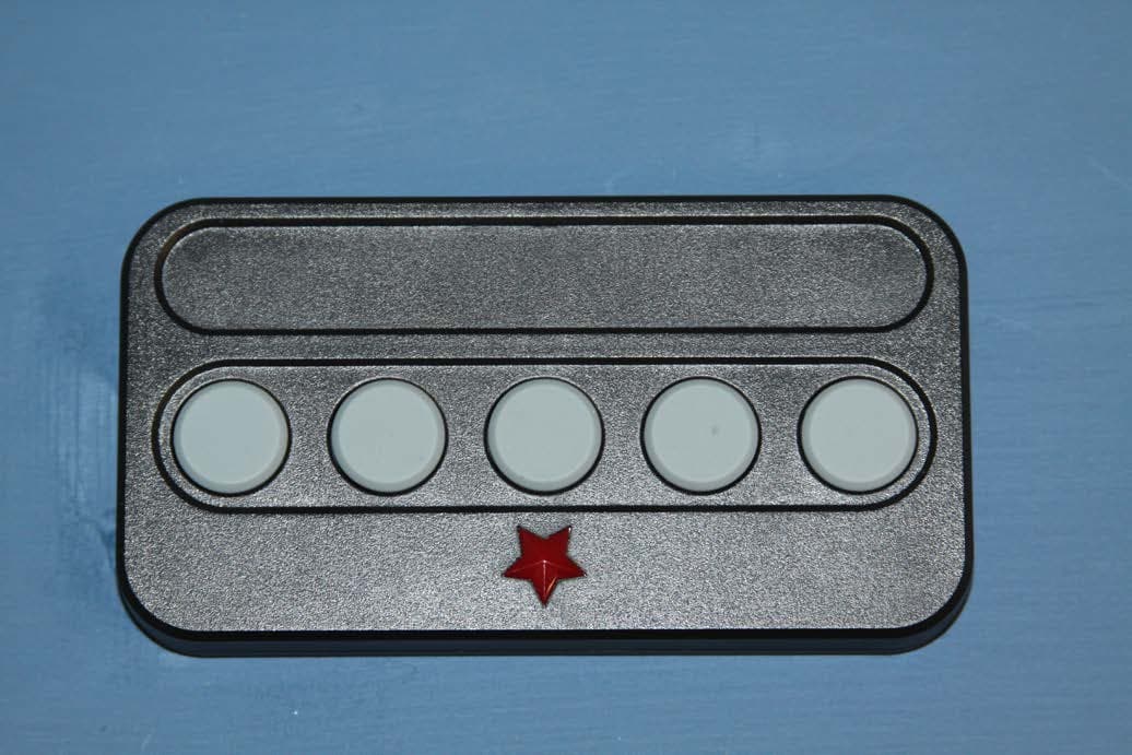
WH2-2610S
Aug 20, 20155 KEY BUTTON TRANSMITTER
Equipment Class
DSC - Part 15 Security/Remote Control Transmitter
WH2-2610D
Jun 07, 2015Remote Transmitter
Equipment Class
DSC - Part 15 Security/Remote Control Transmitter
WH2-2611CA
Dec 16, 2014Paging Transmitter
Equipment Class
TNB - Licensed Non-Broadcast Station Transmitter