WIOWS3006WHDI Wireless Video Transmitter
JUPITER TECHNOLOGY (WUXI) CO.,LTD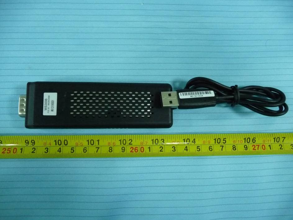
Click to zoom
Application Details
- Equipment Class
- NII - Unlicensed National Information Infrastructure TX
- Date of Grant
- Sep 02, 2013
- Application Purpose
- Original Equipment
- Date of Application
- Sep 02, 2013
- Equipment Note
- WHDI Wireless Video Transmitter
- Frequency Range
- 5755.00000000 - 5795.00000000
- Country
- China
Documents & Files
Document Text
Text extracted from the exhibit documents filed with the FCC. Open a document above to read the original.
Users Manual
WS3006 User manual JUPITER TECHNOLOGY(WUXI)CO.,LTD - 1 - User manual Step1: Install the Wireless HD receiver equipment a) Connect the receiving device to HD displayers (LCD, LED, etc.) using the VGA cable; b) Connect 5V DC power adapter to the receiving device, and turn on the power switch. Step2:Install the wireless HD transmitter equipment a)The transmitting device is connected directly to the HD signal source ( laptop computer, PS3 or others) by the VGA interface; b) Connect the USB connector of the transmitter to computer USB Interface, or a USB power adapter (Current > 0.7A). Step3:Connect the device transmitting the signal source a)The wireless connection will establish automatically, During this time the blue light of wireless HD transmitter will flash, After the wireless connection complete, the blue light keeps bright. The entire process of the connection takes about 15 seconds. Figure 1 Schematic diagram of the wireless HD video systems to connect Troubleshooting Step1: Wireless HD receiver device is connected to HD displays Step2: Wireless HD transmitter device is connected HD sources Step3: Wait for the wireless connection about 15 seconds Wireless HD receiver equipment Wireless HD transmission equipment Source: PC,PS3.... 5V 2A adapter VGA cable Monitor:LCD、LED...... USB power Note: See Troubleshooting (2,3 pages) - Transmitter must be connect to USB 3.0 - If the PC does not support automatic image output, you need to do it manual. - Connect the Transmitter to the video player or an external display device, if there is no USB power supply interface, you can use USB power adapter. - If the wireless connection can’t connect successfully, you can try using the remote control POWER button to restart the receiver. The receiver will reboot automatically and try to connect to the transmitter again. WS3006 User manual JUPITER TECHNOLOGY(WUXI)CO.,LTD - 2 - Before reading this chapter, please do the following confirmation: 1) Connect the source and displayers directly through the VGA cable and watch if it can transfer images, if you still can’t watch the transfer images and sound, you need to make sure the signal source or displayer problems. 2) To confirm the source of the VGA port is working properly, please check if the notebook graphics driver installation complete. 3) Make sure the display device's VGA port is working properly, and refer to operating manual for the settings are correct. 1 Can’t establish the wireless connection 1) Make sure the range of the transmitter and receiver is no more than 10 meters indoor. 2) Make sure between the transmitter and the receiver has no metal objects or wall which can block the signal. 3) When the receiver is connected, the displayer in the receiving end will show the operation menu. If the menu does not appear, please make sure the receiver's power adapter is connected, the switch is on; and the receiver connect to the monitor through the VGA cable. 4) Make sure the wireless HDTV transmitter is connected correctly, Try to re-plug the USB connector, change a USB interface, or use a USB power adapter; Also try to re-plug the VGA connector. 2 can’t see any picture on monitor 1) Check the display settings again, to confirm the signal input port on the monitor has been selected to the correct VGA input port 2) Verify the wireless has connected 3) If the wireless is connected, still no image on the monitor, the issue occurs as in Figure 2; please do the following: Check the signal source, such as PC’s confirmation of signal output. For Windows 7 operating system can use the WIN key + P-> select Copy For Windows XP operating system can output images right function menu For example, you can use ASUS laptop series can output FN + F8. 4) Check the list of devices, make sure the chosen equipment is the right one. 5) Change the resolution on source side WS3006 User manual JUPITER TECHNOLOGY(WUXI)CO.,LTD - 3 - Figure 2 3 Some noise in picture on monitor 1) Try to reduce the distance between the wireless transmitter and the receiver. 2) Try to change display resolution 3) Reset the connection of the transmitter and receiver. 4 No sound on the receiver side. 1) Confirm the source of the graphics driver is installed correctly. 2) Make sure the external display device is not set to mute mode. This device complies with part 15 of the FCC Rules. Operation is subject to the following two conditions: (1) This device may not cause harmful interference, and (2) this device must accept any interference received, including interference that may cause undesired operation. changes or modifications not expressly approved by the party responsible for compliance could void the user's authority to operate the equipment. IMPORTANT NOTE: FCC Radiation Exposure Statement: This equipment complies with FCC radiation exposure limits set forth for an uncontrolled environment . This transmitter must not be co-located or operating in conjunction with any other antenna or transmitter.
Cover Letter(s)
Jupiter Technology (Wuxi) Co.,Ltd. NO.13 Minjiang Road, Wuxi State High&New Technology Industry Development Zone, Jiangsu, P.R. China Tel:0510-85228800 Fax: 0510-88555980 FCC Authorization 2013-7-4 FEDERAL COMMUNICATIONS COMMISSIONS Authorization and Evaluation Division 7435 Oakland Mills Road Columbia, MD 21046 Subject: Agent Authorization To whom it may concern: We, Jupiter Technology (Wuxi) Co.,Ltd. ,the undersigned, hereby authorizes Bay Area Compliance Laboratories Corporation to act on its behalf in all matters relating to application for Equipment authorization, including the signing of all documents relating to these matters. All acts carried out by Bay Area Compliance Laboratories Corp. on our behalf shall have the same effect as our own action. We, Jupiter Technology (Wuxi) Co.,Ltd. ,the undersigned, hereby certify that we are not subject to a denial of federal benefits, that includes FCC benefits, pursuant to Section 5301 of the Anti-Drug Abuse Act of 1988, 21 U.S.C. 853(a). This authorization is valid until further written notice from the applicant. Sincerely Yours, Signature: Kunjing Wu QE
Cover Letter(s)
Jupiter Technology (Wuxi) Co.,Ltd. NO.13 Minjiang Road, Wuxi State High&New Technology Industry Development Zone, Jiangsu, P.R. China Tel:0510-85228800 Fax: 0510-88555980 FCC Confidential Authorization 2013-7-4 FEDERAL COMMUNICATIONS COMMISSIONS Authorization and Evaluation Division 7435 Oakland Mills Road Columbia, MD 21046 Confidentiality Request regarding application for certification of FCC ID: WIOWS3006 Pursuant to Sections 0.457 and 0.459 of the Commission’s Rules, we hereby request confidential treatment of information accompanying this application as outlined below: Block Diagram--- (Long term) Circuit Description--- (Long term) Detailed Circuit Schematics of EUT--- (Long term) The above materials contain trade secrets and proprietary information not customarily released to the public. The public disclosure of these materials may be harmful to the applicant and provide unjustified benefits to its competitors. The applicant understands that pursuant to Section 0.457 of the Rules, disclosure of this application and all accompanying documentation will not be made before the date of the grant for this application. Sincerely Yours, Signature: Kunjing Wu QE
External Photos
EXHIBIT B - EUT EXTERNAL PHOTOGRAPHS EUT – Front View EUT – Rear View EUT – Top View EUT – BottomView EUT – Left View EUT – Right View
ID Label/Location Info
EXHIBIT A - FCC ID LABELING AND LOCATION FCC ID Label FCC ID Label Location The label shown shall be permanently affixed at a conspicuous location on the device and be readily visible to the user at the time purchase (Labeling requirements per 2.925) Label here
Internal Photos
EXHIBIT C - EUT INTERNAL PHOTOGRAPHS EUT – Cover off View EUT – Main Board Top View Antenna 2 Antenna 1 EUT – Main Board Bottom View
RF Exposure Info
Bay Area Compliance Laboratories Corp. (Shenzhen) Report No.: RSZ130530003-00 FCC Part 15.407 Page 8 of 61 FCC §15.407 (f) & §2.1093 – RF EXPOSURE Applicable Standard According to FCC §2.1093 and §1.1307(b) (1), systems operating under the provisions of this section shall be operated in a manner that ensure that the public is not exposed to radio frequency energy level in excess of the Commission’s guideline. According to KDB 447498 D01 General RF Exposure Guidance v05 Result According to FCC KDB 447498 D01 General RF Exposure Guidance v05 generic portable criteria The distance between antenna and test point is 5 mm. The max conducted output power is 5.66 dBm (3.681 mW) for band: 5725-5825 MHz and 5.58 dBm (3.614 mW) for band: 5150-5250 MHz. The antenna gain is 0 dBi. So the max output power (EIRP) is 5.66 dBm (3.681 mW) for band: 5725-5825 MHz and 5.58 dBm (3.614 mW) for band: 5150-5250 MHz. According to the Appendix A of KDB 447498, the exclusion thresholds for 5200 MHz is 7 mW and for 5800 MHz is 6 mW. Conclusion: The time-averaged output power is 3.681mW<the exclusion thresholds 6 mW for band 5725-5825 MHz, and 3.614mW<the exclusion thresholds 7 mW for band 5150-5250 MHz, so stand-alone SAR evaluation is not required.
Test Report
Note: This test report is prepared for the customer shown above and for the equipment described herein. It may not be duplicated or used in part without prior written consent from Bay Area Compliance Laboratories Corp. FCC PART 15.407 TEST REPORT For Jupiter Technology (Wuxi) Co., Ltd. NO.13 Minjiang Road, Wuxi State High&New Technology Industry Development Zone, Jiangsu, P.R. China Report Type: Original Report Product Type: WHDI Wireless Video Transmitter Test Engineer: Simon Wang Report Number: RSZ130530003-00 Report Date: 2013-08-30 Reviewed By: Sula Huang RF Engineer Prepared By: Bay Area Compliance Laboratories Corp. (Shenzhen) 6/F, the 3rd Phase of WanLi Industrial Building ShiHua Road, FuTian Free Trade Zone Shenzhen, Guangdong, China Tel: +86-755-33320018 Fax: +86-755-33320008 www.baclcorp.com.cn FCC ID: WIOWS3006 Bay Area Compliance Laboratories Corp. (Shenzhen) Report No.: RSZ130530003-00 FCC Part 15.407 Page 2 of 61 TABLE OF CONTENTS GENERAL INFORMATION.......................................................................................................................................4 PRODUCT DESCRIPTION FOR EQUIPMENT UNDER TEST (EUT) .....................................................................................4 OBJECTIVE...................................................................................................................................................................4 RELATED SUBMITTAL(S)/GRANT(S).............................................................................................................................4 TEST METHODOLOGY..................................................................................................................................................4 TEST FACILITY.............................................................................................................................................................4 SYSTEM TEST CONFIGURATION ..........................................................................................................................5 DESCRIPTION OF TEST CONFIGURATION......................................................................................................................5 EUT EXERCISE SOFTWARE..........................................................................................................................................5 EQUIPMENT MODIFICATIONS.......................................................................................................................................5 LOCAL SUPPORT EQUIPMENT.......................................................................................................................................5 EXTERNAL CABLE........................................................................................................................................................5 BLOCK DIAGRAM OF TEST SETUP................................................................................................................................6 SUMMARY OF TEST RESULTS...............................................................................................................................7 FCC §15.407 (f) & §2.1093 – RF EXPOSURE ............................................................................................................8 APPLICABLE STANDARD..............................................................................................................................................8 RESULT........................................................................................................................................................................8 FCC §15.203 – ANTENNA REQUIREMENT ............................................................................................................9 APPLICABLE STANDARD..............................................................................................................................................9 ANTENNA CONNECTOR CONSTRUCTION......................................................................................................................9 FCC §15.407 (b) (6) §15.207 (a) – CONDUCTED EMISSIONS .............................................................................10 APPLICABLE STANDARD............................................................................................................................................10 MEASUREMENT UNCERTAINTY..................................................................................................................................10 EUT SETUP................................................................................................................................................................10 EMI TEST RECEIVER SETUP.......................................................................................................................................11 TEST EQUIPMENT LIST AND DETAILS.........................................................................................................................11 TEST PROCEDURE......................................................................................................................................................11 TEST RESULTS SUMMARY..........................................................................................................................................11 TEST DATA................................................................................................................................................................11 §15.205 & §15.209 & §15.407(B) (1),(6),(7) – UNDESIRABLE EMISSION & RESTRICTED BANDS.............14 APPLICABLE STANDARD............................................................................................................................................14 MEASUREMENT UNCERTAINTY..................................................................................................................................14 EUT SETUP.......…
Text truncated - open the document above for the full version.
Test Setup Photos
EXHIBIT C - TEST SETUP PHOTOGRAPHS Conducted Emissions- Front View Conducted Emissions- Side View Radiated Emissions - Front View (Below 1 GHz) Radiated Emissions - Rear View (Below 1 GHz) Radiated Emissions - Front View (Above 1 GHz) Radiated Emissions - Rear View (Above 1 GHz)
Contact Information
Applicant
Kunjing Wu
Test Firm
Bay Area Compliance Laboratory Corp. (Shenzhen)John Chan
Technical Specifications
| # | Rule Parts | Frequency Range | Power Output |
|---|---|---|---|
| 2 | 15E | 5.75 GHz - 5.79 GHz | 3.68 mW |
Other Applications from JUPITER TECHNOLOGY (WUXI) CO.,LTD
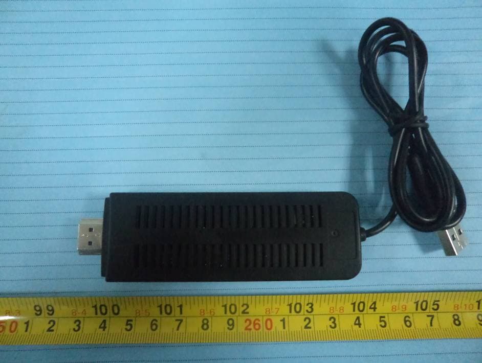
WIOWS3007
Sep 03, 2013WHDI Wireless Video Transmitter
Equipment Class
NII - Unlicensed National Information Infrastructure TX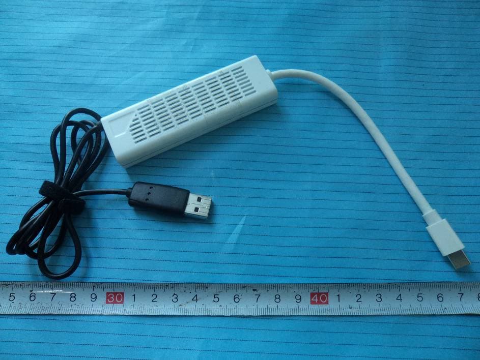
WIOWS3004
Nov 01, 2011WHDI 5.8 GHz Mini Displayport Kit
Equipment Class
DTS - Digital Transmission System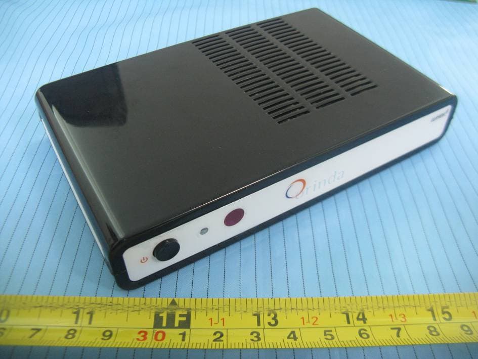
WIOWS3002
Sep 15, 2011WHDI 5.8GHz WIRELESS PROJECTOR
Equipment Class
DTS - Digital Transmission System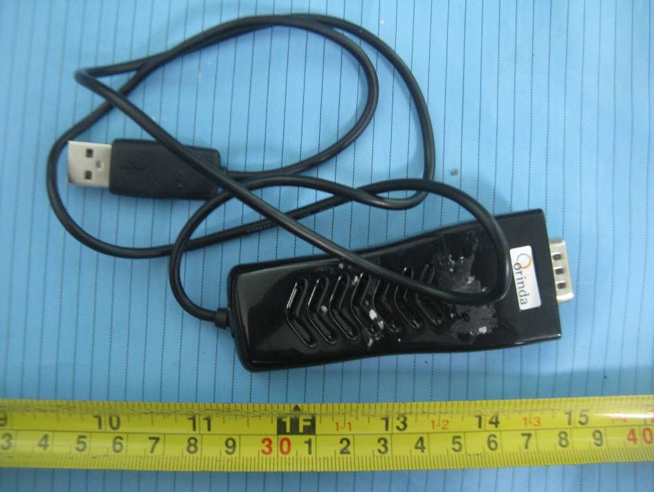
WIOWS3003
Sep 15, 2011WHDI 5.8GHz WIRELESS PROJECTOR
Equipment Class
DTS - Digital Transmission System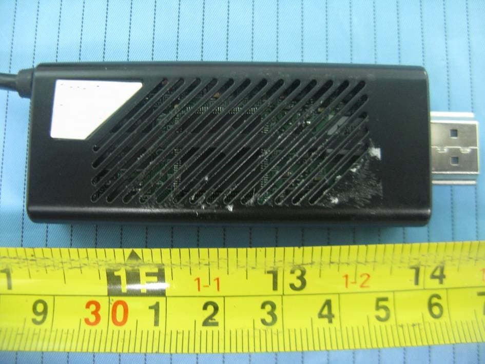
WIOWS3001
Sep 08, 2011WHDI 5.8 GHz WIRELESS TV
Equipment Class
NII - Unlicensed National Information Infrastructure TX