WJ9-ARU4ELCU6UHF RFID Reader
KATHREIN Sachsen GmbH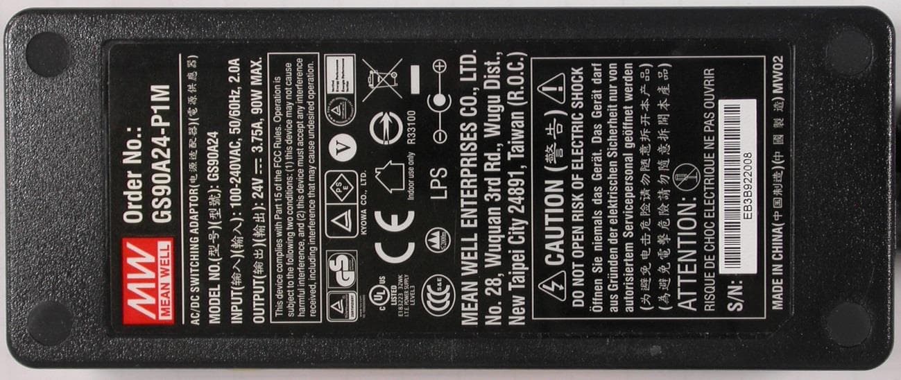
Click to zoom
Application Details
- Equipment Class
- DSS - Part 15 Spread Spectrum Transmitter
- Date of Grant
- Apr 23, 2015
- Application Purpose
- Original Equipment
- Date of Application
- Apr 22, 2015
- Equipment Note
- UHF RFID Reader
- Frequency Range
- 902.25000000 - 927.75000000
- Company
- KATHREIN Sachsen GmbH
- Country
- Germany
Documents & Files
Document Text
Text extracted from the exhibit documents filed with the FCC. Open a document above to read the original.
Users Manual
English Installation manual for Kathrein RFID UHF-Antennas Installation manual antennas Version 2.52 This document is valid for all Kathrein RFID antennas and describes the construction and the installation of the antennas. Low Range Antennas Mid Range Antennas SMSH Antennas / -modul SMSH © KRAI Antennas / -modul Wide Range Antennas Wide Range © KRAI Antennas date of creation: 01.06.2012 Document No. 936B059 Installation manual antennas 2 Modifications, misprints and errors excepted EnglishInstallation manual antennas RFID-UHF-Antennas Type:Order number: U-LoRa ETSI/FCC; Ultra Low Range antenna ETSI/FCC, 865-928 MHz52010092 LoRa ETSI; Low Range-antenna ETSI, 865-870 MHz52010084 LoRa FCC; Low Range-antenna FCC, 902-928 MHz52010085 Type:Order number: MiRa ETSI; Mid Range antenna ETSI, 865-870 MHz, 100° circular52010082 MiRa FCC; Mid Range antenna FCC, 902-928 MHz, 100° circular52010083 S-MiRa ETSI/FCC; Short-Mid Range antenna ETSI/FCC, 865-928 MHz, 100° circular 52010172 Type:Order number: SMSH-30-30-antenna modul without protective cover52010219 SMSH-30-30-KRAI-antenna with protective cover52010258 SMSH-HighGain-30-30-KRAI-EU-antenna with protective cover52010259 SMSH-HighGain-30-30-EU-antenna modul without protective cover52010260 Type:Order number: WiRa 70° ETSI; Wide Range antenna ETSI, 865-870 MHz, 70° circular52010078 WiRa 70° FCC; Wide Range antenna FCC, 902-928 MHz, 70° circular52010079 WiRa-70-KRAI-ETSI; Wide Range © KRAI antenna ETSI, 865-868 MHz52010193 WiRa-70-KRAI-FCC; Wide Range © KRAI antenna FCC, 902-928 MHz52010194 Type:Order number: WiRa-40-linear-ETSI; Wide Range antenna 40°/40°, linear, ETSI52010251 WiRa-40-linear-FCC; Wide Range antenna 40°/40°, linear, FCC52010252 Type:Order number: WiRa 30° ETSI; Wide Range-antenna ETSI, 865-870 MHz, 30° circular52010086 WiRa 30° FCC; Wide Range-antenna FCC, 902-928 MHz, 30° circular52010087 WiRa-30-CSB-KRAI-ETSI; Wide Range Switch Beam © KRAI antenna ETSI, 865-868 MHz, 30° circular 52010227 WiRa-30-CSB-KRAI-FCC Wide Range Switch Beam © KRAI antenna FCC, 902-928 MHz, 30° circular 52010228 WiRa-30-linear-ETSI; Wide Range antenna 30°/70°, linear, ETS52010248 WiRa-30-linear-FCC; Wide Range antenna 30°/70°, linear, FCC52010249 This manual applies to the following RFID UHF types: Installation manual antennas 3 Modifications, misprints and errors excepted English Foreword and general information The reproduction or distribution of this document or extracts from it in whatever form and by whatever means (electronic or mechanical) for whatever purpose is permitted only with the prior written permission of Kathrein. Kathrein accepts no liability for omissions or inaccuracies in this document or in relation to the provision or use of the information contained in this document. Kathrein reserves the right to change the products described in this document and does not accept any liability in relation to the application or usage of the products described in this manual. This document and the information contained in it are proprietary information of Kathrein and should be treated as confidential. Kathrein provides this document to its customers in connection with contacts of sale for the products described therein. If the person in possession of this document, being a legal or natural person, is not a contractual sales partner of Kathrein, or Kathrein has not intended him by other means as the recipient of the document and the information contained therein, the person in possession is hereby informed that the use of this document is unlawful and a violation of the rights of Kathrein. Copyright notice The information in this manual was correct at the time of editorial deadline. We reserve the right however to make changes at any time and without prior notice. This document was prepared for specialist personal who install, configure and place in operation the reader. Scope The information contained in this manual is intended for the support of the development process and as development guidance for the customer. In addition this manual offers supporting information about the standards to be applied at the place of installation and the relevant safety standards for installation and configuration of the Kathrein reader. General information This manual contains information on the installation, configuration, operation and maintenance of the reader. In addition it gives detailed technical data in order better to familiarise the user with the features of the reader. In order to ensure a long working life and fault-free operation, this manual should therefore be read carefully and all the instructions and information contained in it should be complied with. Warranty Switching on the AC or DC power supply prior to connecting the LAN cable is considered incorrect installation. Any functional defect arising as a result is excluded from the warranty/guarantee. Before installing or servicing the reader, the person concerned must have read the manual and understood its contents. Kathrein accepts no liability if the customer fails to implement the precautions listed here. In such cases, any claims under the warranty/guarantee are void. Disposal instruction Electronic equipment is not classed as household waste and must be disposed of properly in accordance with Directive 2002/96/EC OF THE EUROPEAN PARLIAMENT AND OF THE COUNCIL of 27 January 2003 on used electrical and electronic equipment. At the end of its service life, take this device for disposal at a designated public collection point. Used batteries are special waste! Do not put used batteries into your domestic waste; instead take them to a collection point for used batteries! Installation manual antennas 4 Modifications, misprints and errors excepted English List of contents Abbreviatiions used in Application note: CKConnecting Kit CSBCircular Switsch Beam DINDeutsches Institut für Normung (German Institut for Standardisation) EIFF Effective Isotropic Field Factor EIFF shows the field isoltaion from far…
Text truncated - open the document above for the full version.
Users Manual
Installation manual for Kathrein RFID UHF-Reader Installation manual Reader English This document is valid for all Kathrein RFID readers and describes the construction and commissioning of the readers. Version 1.03 date of creation: 01.06.2012 document no.: 936B057 RRU4 ARU4 M-ARU ERU RDR Installation manual Reader 2 Modifications, misprints and errors excepted. EnglishInstallation manual Reader This manual applies to the followings ARU4 types: Type:Order number: ARU4-RS4-E652010099 ARU4-ETG-E652010100 ARU4-ETL-E652010101 ARU4-RS4-U652010102 ARU4-ETG-U652010103 ARU4-ETL-U652010104 ARU4-ELK-E652010225 ARU4-ELK-U652010226 ARU4-ELC-U652010171 This manual applies to the followings M-ARU types: Type:Order number: M-ARU-RS232 ETSI52010135 M-ARU-RS232 FCC52010136 M-ARU-ETH-E652010198 M-ARU-ETH-U652010199 RFID-UHF-Reader This manual applies to the followings RRU4 types: Type:Order number: RRU4-RS4-E652010093 RRU4-ETG-E652010094 RRU4-ETL-E652010095 RRU4-RS4-U652010096 RRU4-ETG-U652010097 RRU4-ELC-E6 © KRAI52010180 RRU4-ELC-U6 © KRAI52010181 This manual applies to the followings ERU types: Type:Order number: ERU-ETG-E452010190 ERU4-ETG-U452010191 This manual applies to the followings RDR types: Type:Order number: RDR-ETH-E452010200 RDR-ETH-U452010201 Installation manual Reader 3 Modifications, misprints and errors excepted English Foreword and general information The reproduction or distribution of this document or extracts from it in whatever form and by whatever means (electronic or mechanical) for whatever purpose is permitted only with the prior written permission of Kathrein. Kathrein accepts no liability for omissions or inaccuracies in this document or in relation to the provision or use of the information contained in this document. Kathrein reserves the right to change the products described in this document and does not accept any liability in relation to the application or usage of the products described in this manual. This document and the information contained in it are proprietary information of Kathrein and should be treated as confidential. Kathrein provides this document to its customers in connection with contacts of sale for the products described therein. If the person in possession of this document, being a legal or natural person, is not a contractual sales partner of Kathrein, or Kathrein has not intended him by other means as the recipient of the document and the information contained therein, the person in possession is hereby informed that the use of this document is unlawful and a violation of the rights of Kathrein. Copyright notice The information in this manual was correct at the time of editorial deadline. We reserve the right however to make changes at any time and without prior notice. This document was prepared for specialist personal who install, configure and place in operation the reader. Scope The information contained in this manual is intended for the support of the development process and as development guidance for the customer. In addition this manual offers supporting information about the standards to be applied at the place of installation and the relevant safety standards for installation and configuration of the Kathrein reader. General information This manual contains information on the installation, configuration, operation and maintenance of the reader. In addition it gives detailed technical data in order better to familiarise the user with the features of the reader. In order to ensure a long working life and fault-free operation, this manual should therefore be read carefully and all the instructions and information contained in it should be complied with. Warranty Switching on the AC or DC power supply prior to connecting the LAN cable is considered incorrect installation. Any functional defect arising as a result is excluded from the warranty/guarantee. Before installing or servicing the reader, the person concerned must have read the manual and understood its contents. Kathrein accepts no liability if the customer fails to implement the precautions listed here. In such cases, any claims under the warranty/guarantee are void. Disposal instruction Electronic equipment is not classed as household waste and must be disposed of properly in accordance with Directive 2002/96/EC OF THE EUROPEAN PARLIAMENT AND OF THE COUNCIL of 27 January 2003 on used electrical and electronic equipment. At the end of its service life, take this device for disposal at a designated public collection point. Used batteries are special waste! Do not put used batteries into your domestic waste; instead take them to a collection point for used batteries! Further reading on this manual is as ((A)) in section 2.2. further reading or 7th list of references listed. Installation manual Reader 4 Modifications, misprints and errors excepted. English List of Contents Foreword and general information 3 List of Contents 4 1. Safety instructions/information 6 2. Introduction 9 2.1. The reader 9 2.2. RFID system 9 2.3. Kathrein RFID Antenna Interface (© KRAI) 11 2.4. Wide Range © KRAI antenna 12 2.5. SMSH © KRAI planar antenna module 12 2.6. Further reference material 13 2.7. Scope of supply 13 2.8. Accessories 14 3. Installation 15 3.1. Selecting the installation site 15 3.2. Installing the reader RRU / ARU 15 3.3. Installing the reader ERU 16 3.4. Installing the reader RDR 17 3.5. Installing the reader M-ARU 18 4. Connections and displays 19 4.1. Power supply 19 4.2. Ethernet connection 20 4.3. RS422-/485 connection 20 4.4. RS232 connection 20 4.5. ERU connection 21 4.6. RDR connection 21 4.7. M-ARU connection 22 4.8. UART transmission (RS232, RS422, RS485 or similar) 23 4.9. Ethernet transmission 25 4.10. Anschlüsse M-ARU, RS232, 25 4.11. Antenna Connection 29 Installation manual Reader 5 Modifications, misprints and errors excepted English List of Contents 4.12. LED 29 4.13. Buzzer 29 5. Software 30 5.1. System requirements 30 5.2. Installation 30 5.3. Operation 34 6. Operating t…
Text truncated - open the document above for the full version.
Users Manual
Installation manual Reader 41 Modifications, misprints and errors excepted English 6. Operating the reader 6.1. Communication 6.1.1. COM header Figure: Tab for the Communication by Ethernet I/O card The communication tab groups together all the functions for establishing connections and configuring the interface cards. The various communication connections are grouped under 3 headers, COM for serial connections via the COM port (RS232/485/422), USB for connections up to version USB 2.0 and Ethernet for connections via TCP/IP. When the connection is established, the program interrogates the information about the installed I/O cards. The information can be viewed and changed via the I/O card configuration. The serial interface is used for communication with the reader via RS232, RS485 and RS422. The RS485/RS422 interface card supports the standard data rates of the serial interface on a PC. A level converter is also required for communication to convert the RS232-compliant signal from the PC into a differential RS485/RS422 signal. A serial COM port on the PC can be opened in this group box. For this purpose the correct serial interface must be selected in the Port drop-down list box. Only the ports available on the PC are displayed in this list box. It is not checked whether this port is already in use by other applications. In the menu below the desired Baud rate must still be set, and if used, the flow control setting. The COM port is opened by clicking on the Connect button, which blocks it for other applications. If this port is already being used by another application, a corresponding error message is output. If the port is free, the reader can be operated using this port. Pressing the Disconnect button breaks the connection and releases the interface again. Installation manual Reader 42 Modifications, misprints and errors excepted. English6. Operating the reader 6.1.3. Ethernet header 6.1.2. USB header If a RRU4 is connected to the PC via USB, the unit is installed in the system as a USB HID-compliant device. Correct logging in can be seen in the program if a reader number appears in the drop-down menu. This number is unique for each reader. If several readers are connected to the PC, the related reader can be selected on this menu. Clicking on Open now establishes the connection between the reader and PC. The Ethernet connection can be achieved by linking the reader into an existing network, or by a direct connection between the reader and a control computer. For direct connection of the reader to the PC, a cross-link cable is required, unless the LAN interface on the PC supports “auto-mdi-x”. Alternatively two standard patch cables and a switch can be used. 6.1.4. Reader to factory default via TCP/IP- broadcast cmd To reset the reader to factory default, the ReaderStart SW will send out a TCP/IP- broadcast cmd. This is only possible 20 seconds after power rebooting. For this select at the folder “Communication”, press “Search for Reader”. All reader in the network will be listed. Select the correct reader and press right mouse button. The following question „Are you sure....“ will be answered with „YES“. Installation manual Reader 43 Modifications, misprints and errors excepted English 6. Operating the reader The user will be informed with the status messages about the progress of the reset process. The final message will be „Reader with IP Address 192.168.0.1 .... (???????????) . Note From reader firmware 2.04, the reader in the ex-works condition has the IP address 192.168.0.1 with the network mask 255.255.255.0. Reader versions earlier than this are configured for DHCP. Note The IP addresses of the control computer and the reader must be in the same IP range, but they must not be the same. The network mask on the other hand must be identical. To integrate the reader into a corporate network, please contact your administrator who will be able to allocate you a spare IP address and assign the correct network mask. Alternatively the reader can also be configured to obtain an IP address automatically. For this service, referred to as DHCP, an appropriate DHCP server must be operating in the network. You can obtain more details about this from your network administrator. In order to establish the connection to the reader, the program offers two options. On the one hand, it is possible to communicate directly with the reader by entering the IP address, on the other hand it is also possible to establish a connection using the reader's host name. For the connection using a host name, there must be a correspondingly configured DHCP server and a DNS in the network. After power up, the reader makes a DHCP request and logs on to the DHCP server. This assigns the reader an IP address and reports the network name and IP address to the DNS server. If now the connection has been established, the IP address of the reader is determined by an enquiry on the DNS server. The establishment of the connection is achieved if the establishment of the connection is selected under the Ethernet header, meaning the selection of the IP address or name. For this, the correct IP address or the host name of the reader must be entered in the corresponding field. Pressing the Connect button then opens the data channel to the reader. If you wish to establish a connection via an IP address, the IP address field must be highlighted and this address entered in it. The connection is established by clicking on the Connect button. Installation manual Reader 44 Modifications, misprints and errors excepted. English 6. Operating the reader 6.1.5.1. RS232 Figure: Configuration of the RS232 card 6.1.5. I/O card configuration The communication interface settings can be changed using the IO card configuration. All available I/O cards are displayed here in the form of tabs. Clicking on the respective tab opens the associated card and displays all respective configuration parameters, together with the card type that was detected…
Text truncated - open the document above for the full version.
Cover Letter(s)
Request for Confidentiality Date: 14.04.2015 Subject: Confidentiality Request for: FCC ID: WJ9-ARU4ELCU6 / IC: 5530C-ARU4ELCU6 Pursuant to FCC 47 CRF 0.457(d) and 0.459 and IC RSP-100, Section 6.4, the applicant requests that a part of the subject FCC application be held confidential. Type of Confidentiality Requested Exhibit Short Term Permanent Block Diagrams Short Term External Photos Short Term Permanent* 1 Internal Photos Short Term Permanent Operation Description/Theory of Operation Short Term Permanent Parts List & Placement/BOM Short Term Permanent Tune-Up Procedure Short Term Permanent Schematics Short Term Test Setup Photos Short Term Permanent* User’s Manual *Note: ______(Insert Explanation as Necessary)______ Kathrein Sachsen GmbH has spent substantial effort in developing this product and it is one of the first of its kind in industry. Having the subject information easily available to "competition" would negate the advantage they have achieved by developing this product. Not protecting the details of the design will result in financial hardship. Permanent Confidentiality: The applicant requests the exhibits listed above as permanently confidential be permanently withheld from public review due to materials that contain trade secrets and proprietary information not customarily released to the public. Short-Term Confidentiality: The applicant requests the exhibits selected above as short term confidential be withheld from public view for a period of (180) 2 ___ days from the date of the Grant of Equipment Authorization and prior to marketing. This is to avoid premature release of sensitive information prior to marketing or release of the product to the public. Applicant is also aware that they are responsible to notify ACB in the event information regarding the product or the product is made available to the public. ACB will then release the documents listed above for public disclosure pursuant to FCC Public Notice DA 04-1705. NOTE for Industry Canada Applications: The applicant understands that until such time that IC distinguishes between Short Term and Permanent Confidentiality, either type of marked exhibit above will simply be marked Confidential when submitted to IC. Sincerely, By: ______________ Thomas Ring, Manager Certification (Signature/Title 3 ) CSA Group Bayern GmbH, Ohmstr. 1-4, 94342 Strasskirchen, Germany Phone: +49 9424 9481-250, Email: [email protected] 1 - The asterisked items (*) require further justification before permanent confidentiality will be allowed. These also currently require review by the FCC under their Permit-But-Ask policy before the grant is issued and can delay completion of an application. Further justification should be added to the note above. One such example for a potted device would be: “The EUT is FULLY potted using a non-removable epoxy based material. Removal of potting material causes irreparable damage to internal circuitry. See photographs exhibits that outline the device before and after potting.” 2 - Please refer to http://acbcert.com/documents/misc-docs/Memo-Short-Term-Vs-Standard-Confidentiality.pdf for complete details. 3 - Must be signed by applicant contact given for applicant on the FCC site, or by the authorized agent if an appropriate authorized agent letter has been provided. Letters should be placed on appropriate letterhead.
External Photos
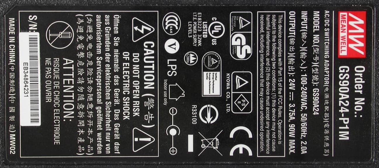
ATTACHMENT A to File No.: T39472-00 CSA Group Bayern GmbH Attachment A to File No. T39472-00HU, page 1 of 22 Ohmstrasse 2-4 94342 Strasskirchen Tel.:+49(0)9424-94810 Fax:+49(0)9424-9481440 Photo documentation of the EUT Model: ARU4-ELC-U6 and ARU4-RS2-U6 ARU4-ELC-U6 - External Views: ATTACHMENT A to File No.: T39472-00 CSA Group Bayern GmbH Attachment A to File No. T39472-00HU, page 2 of 22 Ohmstrasse 2-4 94342 Strasskirchen Tel.:+49(0)9424-94810 Fax:+49(0)9424-9481440 ATTACHMENT A to File No.: T39472-00 CSA Group Bayern GmbH Attachment A to File No. T39472-00HU, page 10 of 22 Ohmstrasse 2-4 94342 Strasskirchen Tel.:+49(0)9424-94810 Fax:+49(0)9424-9481440 ARU4-RS2-U6 - External Views: ATTACHMENT A to File No.: T39472-00 CSA Group Bayern GmbH Attachment A to File No. T39472-00HU, page 11 of 22 Ohmstrasse 2-4 94342 Strasskirchen Tel.:+49(0)9424-94810 Fax:+49(0)9424-9481440 ATTACHMENT A to File No.: T39472-00 CSA Group Bayern GmbH Attachment A to File No. T39472-00HU, page 16 of 22 Ohmstrasse 2-4 94342 Strasskirchen Tel.:+49(0)9424-94810 Fax:+49(0)9424-9481440 Antenna FCC – external - 52010252 Wi-Ra Antenna 40°/40°, linear: ATTACHMENT A to File No.: T39472-00 CSA Group Bayern GmbH Attachment A to File No. T39472-00HU, page 17 of 22 Ohmstrasse 2-4 94342 Strasskirchen Tel.:+49(0)9424-94810 Fax:+49(0)9424-9481440 ATTACHMENT A to File No.: T39472-00 CSA Group Bayern GmbH Attachment A to File No. T39472-00HU, page 18 of 22 Ohmstrasse 2-4 94342 Strasskirchen Tel.:+49(0)9424-94810 Fax:+49(0)9424-9481440 ATTACHMENT A to File No.: T39472-00 CSA Group Bayern GmbH Attachment A to File No. T39472-00HU, page 21 of 22 Ohmstrasse 2-4 94342 Strasskirchen Tel.:+49(0)9424-94810 Fax:+49(0)9424-9481440 Power supply unit: ATTACHMENT A to File No.: T39472-00 CSA Group Bayern GmbH Attachment A to File No. T39472-00HU, page 22 of 22 Ohmstrasse 2-4 94342 Strasskirchen Tel.:+49(0)9424-94810 Fax:+49(0)9424-9481440
ID Label/Location Info
Label Placement
Internal Photos
ATTACHMENT A to File No.: T39472-00 CSA Group Bayern GmbH Attachment A to File No. T39472-00HU, page 3 of 22 Ohmstrasse 2-4 94342 Strasskirchen Tel.:+49(0)9424-94810 Fax:+49(0)9424-9481440 Internal Views: ATTACHMENT A to File No.: T39472-00 CSA Group Bayern GmbH Attachment A to File No. T39472-00HU, page 4 of 22 Ohmstrasse 2-4 94342 Strasskirchen Tel.:+49(0)9424-94810 Fax:+49(0)9424-9481440 ATTACHMENT A to File No.: T39472-00 CSA Group Bayern GmbH Attachment A to File No. T39472-00HU, page 5 of 22 Ohmstrasse 2-4 94342 Strasskirchen Tel.:+49(0)9424-94810 Fax:+49(0)9424-9481440 ATTACHMENT A to File No.: T39472-00 CSA Group Bayern GmbH Attachment A to File No. T39472-00HU, page 6 of 22 Ohmstrasse 2-4 94342 Strasskirchen Tel.:+49(0)9424-94810 Fax:+49(0)9424-9481440 ATTACHMENT A to File No.: T39472-00 CSA Group Bayern GmbH Attachment A to File No. T39472-00HU, page 7 of 22 Ohmstrasse 2-4 94342 Strasskirchen Tel.:+49(0)9424-94810 Fax:+49(0)9424-9481440 ATTACHMENT A to File No.: T39472-00 CSA Group Bayern GmbH Attachment A to File No. T39472-00HU, page 8 of 22 Ohmstrasse 2-4 94342 Strasskirchen Tel.:+49(0)9424-94810 Fax:+49(0)9424-9481440 ATTACHMENT A to File No.: T39472-00 CSA Group Bayern GmbH Attachment A to File No. T39472-00HU, page 9 of 22 Ohmstrasse 2-4 94342 Strasskirchen Tel.:+49(0)9424-94810 Fax:+49(0)9424-9481440 ATTACHMENT A to File No.: T39472-00 CSA Group Bayern GmbH Attachment A to File No. T39472-00HU, page 12 of 22 Ohmstrasse 2-4 94342 Strasskirchen Tel.:+49(0)9424-94810 Fax:+49(0)9424-9481440 Internal Views: ATTACHMENT A to File No.: T39472-00 CSA Group Bayern GmbH Attachment A to File No. T39472-00HU, page 13 of 22 Ohmstrasse 2-4 94342 Strasskirchen Tel.:+49(0)9424-94810 Fax:+49(0)9424-9481440 ATTACHMENT A to File No.: T39472-00 CSA Group Bayern GmbH Attachment A to File No. T39472-00HU, page 14 of 22 Ohmstrasse 2-4 94342 Strasskirchen Tel.:+49(0)9424-94810 Fax:+49(0)9424-9481440 ATTACHMENT A to File No.: T39472-00 CSA Group Bayern GmbH Attachment A to File No. T39472-00HU, page 15 of 22 Ohmstrasse 2-4 94342 Strasskirchen Tel.:+49(0)9424-94810 Fax:+49(0)9424-9481440 ATTACHMENT A to File No.: T39472-00 CSA Group Bayern GmbH Attachment A to File No. T39472-00HU, page 19 of 22 Ohmstrasse 2-4 94342 Strasskirchen Tel.:+49(0)9424-94810 Fax:+49(0)9424-9481440 Antenna FCC – internal - ARU4-ELC-U6: ATTACHMENT A to File No.: T39472-00 CSA Group Bayern GmbH Attachment A to File No. T39472-00HU, page 20 of 22 Ohmstrasse 2-4 94342 Strasskirchen Tel.:+49(0)9424-94810 Fax:+49(0)9424-9481440 Antenna FCC – internal - ARU4-RS2-U6:
RF Exposure Info
ATTACHMENT B to File No.: T39472-00-00HU CSA Group Bayern GmbH Attachment B to File No. T39472-00-00HU, page 1 of 2 Ohmstrasse 2-4 94342 Strasskirchen Tel.:+49(0)9424-94810 Fax:+49(0)9424-9481440 Maximum permissible exposure (MPE) 1.1 For test instruments and accessories used see section 6 Part CPC 2. 1.1.1 Description of the test location Test location: Shielded room S4 1.1.2 Applicable standard According to FCC Part 15, Section 15.247(i): Systems operating under the provisions of this section shall be operated in a manner that the public is not exposed to radio frequency energy levels in excess of the Commission’s guidelines. The test methods used comply with ANSI/IEEE C95.1, “IEEE Standard for Safety Levels with respect to Human Exposure to Radio Frequency Electromagnetic Fields, 3 kHz to 300 GHz”. This test report shows the compliance with the limits for Maximum Permissible Exposure (MPE) specified in FCC Part 1, Section 1.1310 and the criteria to evaluate the environmental impact of human exposure to radio- frequency (RF) radiation as specified in FCC Part 1, Section 1.1307(b). 1.1.3 Description of Measurement The maximum total power input to the antenna has been measured conducted as described in clause 5.3 of this document. Through the Friis transmission formula, the known maximum gain of the antenna and the maximum power, the MPE can be calculated in a defined distance away from the product. Friis transmission formula: P d = 2 **4 * r GP out where P d =power density (mW/cm 2 ) P out = output power to antenna (mW) G = gain of antenna (linear scale) r = distance between antenna and observation point (cm) ATTACHMENT B to File No.: T39472-00-00HU CSA Group Bayern GmbH Attachment B to File No. T39472-00-00HU, page 2 of 2 Ohmstrasse 2-4 94342 Strasskirchen Tel.:+49(0)9424-94810 Fax:+49(0)9424-9481440 1.1.4 Test result a.) Power setting 30.0 dBm = Antenna gain: < 6.0 dBi Channel No. Frequency Max power output to antenna Antenna gain Power density Limit of power density (MHz) (dBm) (mW) (dBi) (mW/cm 2 ) (mW/cm 2 ) 1 902.25 28.58 721.107 6.0 0.5711 0.602 25 914.75 28.32 679.204 6.0 0.5379 0.610 52 927.75 28.03 635.331 6.0 0.5032 0.619 b.) Power setting 23.0 dBm = Antenna gain: 13.0 dBi Channel No. Frequency Max power output to antenna Antenna gain Power density Limit of power density (MHz) (dBm) (mW) (dBi) (mW/cm 2 ) (mW/cm 2 ) 1 902.25 21.68 147.231 13.0 0.5844 0.602 25 914.75 21.54 142.561 13.0 0.5659 0.610 52 927.75 20.31 107.399 13.0 0.4263 0.619 According to FCC Rules 47CFR 2.1093(b) the EUT is not a portable device. The EUT is designed to be used that radiating structures are more than 20 cm outside of the body of the user. (r = 20 cm). Limits for maximum permissible exposure (MPE): Frequency Range (MHz) Electric Field Strength (V/m) Magnetic Field Strength (A/m) Power Density (mW/cm 2 ) Averaging Time (minutes) (B) Limits for General Population / Uncontrolled Exposure 0.3 – 3.0 614 1.63 100 30 3.0 – 30 824/f 2.19/f 180/ f 2 30 30 - 300 27.5 0.073 0.2 30 300-1500 --- --- f/1500 30 1500-100000 --- --- 1.0 30 f = Frequency (MHz) Note: The manufacturer shall state in the manual the minimum cable length for each antenna. Aditionally this shall be stated on the label of the EuT. The requirements are FULFILLED. Remarks:
Test Report
FCC ID: WJ9-ARU4ELCU6 CSA Group Bayern GmbH File No. T39472-00-00HU, page 1 of 62 Ohmstrasse 2-4 94342 Strasskirchen Tel.:+49(0)9424-94810 Fax:+49(0)9424-9481440 Rev. No. 4.0, 2015-04-17 EMI − T E S T R E P O R T - FCC 15.247 - Type / Model Name : ARU4-ELC-U6 and ARU4-RS2-U6 Product Description : UHF RFID Reader Applicant : KATHREIN Sachsen GmbH Address : Lindenstrasse 6 D – 09241 Mühlau Manufacturer : KATHREIN Sachsen GmbH Address : Lindenstrasse 6 D – 09241 Mühlau Licence holder : KATHREIN Sachsen GmbH Address : Lindenstrasse 6 D – 09241 Mühlau Test Result according to the standards listed in clause 1 test standards: POSITIVE Test Report No. : T39472-00-00HU 21. April 2015 _____________________________________________________________________…
Text truncated - open the document above for the full version.
Contact Information
Applicant
Joerg Spranger(Engineer)
Technical Contact
CSA Group Bayern GmbHMarkus Huber
[email protected]49 9424 9481
Ohmstrasse 1-4 · Strasskirchen · Germany
Test Firm
CSA Group Bayern GmbHThomas Weise
Technical Specifications
| # | Rule Parts | Frequency Range | Power Output |
|---|---|---|---|
| 1 | 15C | 902.25 MHz - 927.75 MHz | 721.00 mW |
Other Applications from KATHREIN Sachsen GmbH
WJ9-RRU4ELCU6
Sep 11, 2014RRU4ELCU6
Equipment Class
DSS - Part 15 Spread Spectrum Transmitter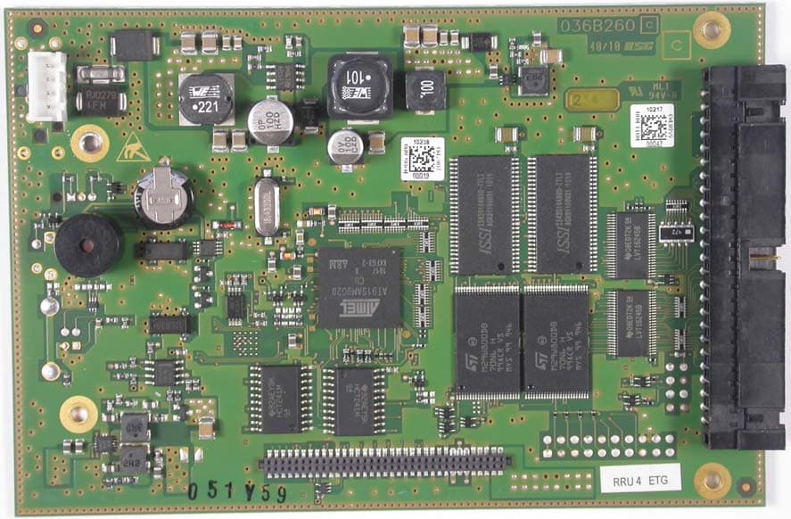
WJ9-RRU4ETGU6
Aug 30, 2011UHF RFID Reader
Equipment Class
JBP - Part 15 Class B Computing Device Peripheral