WJHRP11Wireless Repeater
Centrica Hive Limited
Click to zoom
Application Details
- Equipment Class
- DTS - Digital Transmission System
- Date of Grant
- Jun 03, 2012
- Application Purpose
- Original Equipment
- Date of Application
- Jun 02, 2012
- Equipment Note
- Wireless Repeater
- Frequency Range
- 2405.00000000 - 2475.00000000
- Company
- Centrica Hive Limited
- Country
- United Kingdom
Documents & Files
Document Text
Text extracted from the exhibit documents filed with the FCC. Open a document above to read the original.
Users Manual
2. GE Outdoor Module Press the button on the front of the module to add it to your system. Plug the Outdoor module into an outlet that is no more than 10 foot from your Smart Hub. Remove Device Are you sure that you want to remove your [device name] [device type]? Remove deviceCancel Remove Device To remove your [device name] [device type] then [device instructions]. Cancel Remove Device To remove your [device name] [device type] then [device instructions]. Waiting for device to confrm its removal. The device to be removed should be within 10 feet of the smart hub. Please make sure that you do not use other Iris devices at this time since they may also be removed. Cancel Device Removed The device [device name] [device type] was removed from the your system. To re-add this device return to the device list and select ‘add device’. Okay Repair Network Sometimes when a device is moved to a new place in the home it can loose its connection to the network. This repair network tool searches for missing devices and reconnects them. Please make sure that all your devices are powered before you begin this process. Click okay to begin the process. It can take around 10 minutes to complete. OkayCancel Repairing Network Searching for missing devices. This can take around 10 minutes to complete. Searching... [x] devices found Cancel Repairing Network Search complete - [x] missing devices found. If your device is still missing then follow the guidance on the support site for connecting missing devices. okay
Users Manual
2. • • • •
Users Manual
Iris Smart Button Squeeze sides together then hinge open. Insert battery checking correct orientation. Replace cover. The button will flash until it has been added to your system. Repeat this for all buttons then click ‘ok’ Iris Motion Sensor Squeeze sides together then hinge open. Insert battery checking correct orientation. Replace cover. The sensor will flash until it has been added to your system. Repeat this for all motions sensors then click ‘ok’ Need to use v2 sensor images Iris Wireless Video Camera Plug the camera into a power socket using the supplied cable and adapter and turn on. Connect the camera to a network port on your router using the supplied cable. 1. 2. Repeat this for all cameras then click ‘ok’. Need to use new camera image network Power Blue Line Optical Electricity Meter Reader PROCESS TBD Down load the driver Connect the gateway Start the install Add the reader Pair reader and gateway Pair gateway and hub Iris Door/Window/Cabinet Sensor Squeeze sides together then hinge open. Insert battery checking correct orientation. Replace cover. The sensor will flash until it has been added to your system. Iris Smart Key Fob Lever open the key fob using the supplied tool. Insert battery checking correct orientation. Slide the thin end together then squeeze closed. Key fob will flash until it has been added to your system. Repeat this for all key fobs then click ‘ok’ 2. Iris Smart Plug The light on the front of the Smart Plug will flash until it has been added to your system. Plug the Smart Plug into an outlet that is no more than 10 foot from your smart hub. Repeat this for all smart plugs then click ‘ok’ Use the US smart plug here And a US socket Iris Smart Keypad Remove the back of the keypad as shown Insert the batteries checking correct orientation. The ‘off’ light will flash until it has been added to your system. Repeat this for all keypads then click ‘ok’ RTOA Smart Thermostat Install the thermostat as instructed in the printed manual. TBD [...] will flash until it has been added to your system. 2. GE On/Off Light Switch To include your light switch press the top of the rocker switch. The smart hub will beep when it has been found. Install the switch as instructed in the printed manual. 2. GE Dimmer Light Switch To include your dimmer switch press the top of the rocker switch. The smart hub will beep when it has been found. Install the switch as instructed in the printed manual. 2. GE Outdoor Module To include your outdoor module press the button on the front of the module. The smart hub will beep when it has been found. Plug the Outdoor module into an outlet that is no more than 10 foot from your Smart Hub. Show plugged into a power outlet Show plugged into a power outlet 2. GE Duplex Receptacle To include your duplex receptacle press the button on the front of the receptacle. The smart hub will beep when it has been found. Install the outlet as instructed in the printed manual. 2. GE 3 Way Switch To include your 3 way switch press the top of the rocker switch. The smart hub will beep when it has been found. Install the switch as instructed in the printed manual. Schlage Deadbolt Doorlock - Nickel Follow the printed instructions to install your Smart Deadbolt into your door. Note the 6 digit program code from the sticker on the lock. Enter the six digit program code. Wait for the Schlage button to flash and beep three times. Press the Schlage button and then the number 0. The hub will beep once it has found the lock. Schlage Level Doorlock - Nickel Follow the printed instructions to install your Smart Deadbolt into your door. Note the 6 digit program code from the sticker on the lock. Enter the six digit program code. Wait for the Schlage button to flash and beep three times. Press the Schlage button and then the number 0. The hub will beep once it has found the lock. 2. Iris Range Extender The light on the range extender will flash for a while until it is added to your system. This should take no more than 5 minutes. Plug the range extender into an outlet that is no more than 10 foot from your smart hub.
Users Manual
Account + Account details Enter the account holder name here, as well as the prefered contact email address of the main account holder. This will be the default email address for this account. You can also change your password here - you will need to enter the previous password in order to do this. If you have forgotten your password, go to www.jupitersmarthome.com where you will see a ‘forgotten password’ link - follow this for further instructions. Contact details In this section the default contact telephone and SMS numbers can be entered. These are the contact numbers that will be used for your alerts to yourself from the system. Your address can also be added in here. This includes your zip code which is used by the system to report local weather forecasts in the temperature widget. If this is left blank, your system will not report any external weather or temperature. Settings Set your system time zone here. The system will use this for all timings on the system, meaning you can accurately see what is happening both in real time, and historically. amount that you pay for your electricity. This can be found on your paper or online bill, or by contacting your supplier. The PIN will be required to control your system via SMS and email, so should be a number that is easily remembered and known only to you. It is not a good idea to use the same PIN as your bank card. System Alerts The system alerts can be used to keep you informed of the health of your system. For example; if a battery runs out the relevant device will go missing and will no longer be active on your system. If selected, you will be sent an alert when this is running low, meaning you can change the battery before it dies. You can set up alerts for the following: - Warnings (warnings include: device battery low) Account overview out upon installation. Account + Where can I change my password? Head to ‘account’ and then ‘account details’. You will need to enter the previous password in order to do this. If you have forgotten your password please refer to the ‘forgotten password’ question below. I have forgotten my password, what do I do? If you have forgotten your password, log out or go to www.jupitersmarthome.com where you will see a ‘forgotten password’ link - follow this for further instructions. How do I edit my contact details? Head to ‘account’ where you can then edit these in the following ways: Account details - in this section you can enter the prefered contact email address of the main account holder. This will be the default email address for this account. Contact details - in this section the default contact telephone and SMS numbers can be entered. These are the contact numbers that will be used for alerts to yourself from the system. This can be found on your paper or online bill, or by contacting your supplier. How do I change my PIN? Please head to your ‘account’ and then ‘settings’. Here you can edit your PIN. This will be required to control your system via SMS and email, so should be a number that is easily remembered and known only to you. It is not a good idea to use the same PIN as your bank card. How do I edit my zip code? Head to ‘account’ and then ‘contact details’. Your zip code can be added or edited in here - this is used by the system to gather local weather forecasts and temperature in the temperature widget. If this is left blank, your system will not report any external weather forecast or temperature readings. What are the system alerts and how do I edit them? Head to ‘account’ and then ‘system alerts’. Here you can select which of the below alerts are active on your system. - Warnings (warnings include: device battery low) Intruder Alarm The alarm can be controlled on your website by dragging the slider to the required mode. Please note that it is not possible to to away mode, or vice versa, you must first go into mode. The alarm can be set using a SmartKeyfob . Press the away button (the button with the stickman outside the house) once to set the alarm to away mode. Hold down the away button for three seconds to set the alarm to night mode. Press the home button (stickman inside the house) once to set the alarm to home mode or cancel an activated alarm. You can also control your alarm using SMS or email. Send an SMS to +44 78-6001-5215 or 010-4478-6001-5215 and type your command followed by your PIN, or email [email protected] with the command and your PIN in the subject line. For a list of commands you can use, please check the remote control help guide. Should you attempt to arm the system while a SmartContact sensor is open, the system will display a warning. You may still arm the system - however the indicated sensor will need to close and then open before it will trigger the alarm. go directly from night When the intruder alarm is activated, the alarm widget which sensor triggered the alarm and at what time this happened. The hub will now be playing an alarm, warning any intruder that the alarm has been activated and the + Alarm overview Clicking the intruder alarm widget navigates to an overview of the alarm system.This view shows the current alarm mode as well as which sensors on your system are in use and currently active with the intruder, panic and emergency alarms. You will also be able to see whether any SmartContact sensors are currently opened or closed. Changing the alarm mode Devices This section allows you to decide which devices are to be active for away and night mode on your intruder alarm system, emergency alarm and also your panic button. Simply tick and untick the devices where required. Ensure you select ‘submit’ when you are happy with any changes you make - alternatively select ‘reset’ to return these settings to default set up. Settings You can decide on timings on your alarm, so for example allowing yourself more time to leave the house after arming, or reducing the time between sensors being triggered and the alarm sounding. You can also decide on h…
Text truncated - open the document above for the full version.
Users Manual
comfort & control kit quick start guide Kit contains: Batteries, Ethernet cable, power cord and mounting tape included. • smart thermostat • smart hub • smart plug Congratulations on your purchase of an Iris ™ comfort & control kit. It’s easy to install your system. Let’s get started. Follow these easy steps to install your comfort & control kit. ©2012 Lowe's Companies, Inc. All rights reserved. Lowe's, the gable design and Never Stop Improving are trademarks of LF, LLC. • Visit lowes.com/iris • Click on Register and we’ll walk you through the steps. • For additional help please visit lowes.com/iris/support. For more information please call 1-866-555-IRIS. ready to install? Before you get started, please check that you have the following: • An hour to spare. Be prepared to complete the installation of all kit components at the same time. • Home router with an open Ethernet port • Open power outlet near your router • Broadband always-on internet service Register There are four stages to complete the Iris ™ set-up. Once you register, we’ll walk you through each: 1. Hub Set-up 2. Account Details 3. Service Options 4. Powering and Pairing Devices 8.6 6.5
Cover Letter(s)
Page 1 of 1 American TCB 6731 Whittier Avenue, Suite C110 McLean, VA. 22101 FCC Application for Alertme.com Ltd, FCC ID: WJHRP11 To whom it may concern: The enclosed documents constitute a formal submittal and application for Equipment Authorization for a combination 2.4GHz DTS transceiver and 902.4MHz transceiver pursuant to the following rules: Subpart C of Part 15 of FCC Rules (CFR 47), Intentional Radiators Elliott Laboratories/NTS, as duly authorized agent prepared this submittal. A copy of the letter of our appointment as agent is included with the application. If there are any questions or if further information is needed, please contact Elliott Laboratories for assistance. Sincerely, David W. Bare Chief Engineer
ID Label/Location Info
13.0 27.0 R0.5 0.1 NOTES: MATERIAL: WHITE MYLAR (POLYESTER FILM)1. PRINT: BLACK (FILLED TEXT)2. ADHESIVE: PERMANENT ADHESIVE BACKED3. REVISIONS REV.DESCRIPTIONDATEDRAWNAPPROVED AFirst Issue05-03-12RGFDPG BCurrent rating specified instead of power rating08-05-12RGFML CFCC Logo Removed11-05-12MT DO NOT SCALE DRAWING DIMENSIONS ARE IN MM TOLERANCES: ANGULAR: 0.5 0 DECIMAL PLACES 0.5mm 1 DECIMAL PLACES 0.2mm 2 DECIMAL PLACES 0.1mm THE INFORMATION CONTAINED IN THIS DRAWING IS THE SOLE PROPERTY OF ALERTME.COM LTD. ANY REPRODUCTION IN PART OR AS A WHOLE WITHOUT THE WRITTEN PERMISSION OF ALERTME.COM LTD IS PROHIBITED. PROPRIETARY AND CONFIDENTIAL 1234 A B C D E F MATERIAL FINISH DATE ALERTME.COM COMPASS HOUSE 80 NEWMARKET ROAD CAMBRIDGE +44 (0)1223 222150 ART0135 RevC-0 Lowes Range Extender ID Label DRAWN BY ANY QUESTIONS? PLEASE ASK! Sheet 1 of 1 SCALE 2:1 05/03/2012R FARN SEE NOTES SEE NOTES 0.1 NOTES: MATERIAL: WHITE MYLAR (POLYESTER FILM)1. PRINT: BLACK (FILLED TEXT)2. ADHESIVE: PERMANENT ADHESIVE BACKED3. REVISIONS REV.DESCRIPTIONDATEDRAWNAPPROVED AFirst Issue05-03-12RGFDPG BCurrent rating specified instead of power rating08-05-12RGFML CFCC Logo Removed11-05-12MT DO NOT SCALE DRAWING DIMENSIONS ARE IN MM TOLERANCES: ANGULAR: 0.5 0 DECIMAL PLACES 0.5mm 1 DECIMAL PLACES 0.2mm 2 DECIMAL PLACES 0.1mm THE INFORMATION CONTAINED IN THIS DRAWING IS THE SOLE PROPERTY OF ALERTME.COM LTD. ANY REPRODUCTION IN PART OR AS A WHOLE WITHOUT THE WRITTEN PERMISSION OF ALERTME.COM LTD IS PROHIBITED. PROPRIETARY AND CONFIDENTIAL 1234 A B C D E F MATERIAL FINISH DATE ALERTME.COM COMPASS HOUSE 80 NEWMARKET ROAD CAMBRIDGE +44 (0)1223 222150 ART0134 RevC-0 US Repeater Plug Label DRAWN BY ANY QUESTIONS? PLEASE ASK! Sheet 1 of 1 SCALE 2:1 05/03/2012R FARN SEE NOTES SEE NOTES
Test Report
|---------- ( Cambridge Ltd. ) ----------| Testing EMCEMC Consultancy EMC Training or : 01223 241140 (accounts) 23, Headington Drive, Cambridge. CB1 9HE Tel : 01954 251974 (test site) Fax : 01954 251907 email: [email protected] web : www.dbtechnology.co.uk REPORT ON ELECTROMAGNETIC COMPATIBILITY TESTS Performed at: TWENTY PENCE TEST SITE Twenty Pence Road, Cottenham, Cambridge U.K. CB24 8PS on AlertMe.com Ltd REP800/REP130 (FCC Part 15.247 measurements only) dated 19th May 2012 Document History DBPBAC Power conducted emissions 9kHz RBW clarified. 1 and 1631/05/122 Initial release19/05/121 Approved by Revised by Description of modifications Affected page(s) DateIssue Based on report template: v090319 1 of 56 Page: Test Report T4335 Test No: FCC ID: WJHRP11 R3094A 2 Report No: Issue No: This report shall not be reproduced except in full, without the written approval of: dB Technology (Cambridge) Ltd. Equipment Under Test (EUT):REP800/REP130 Test Commissioned by:AlertMe.com Ltd Compass House 80 Newmarket Road Cambridge CB5 8DZ Representative:Bruce Benson Test Started:28th April 2012 Test Completed:17th May 2012 Test Engineer:Dave Smith Date of Report:19th May 2012 Written by:Dave SmithChecked by:Derek Barlow Signature:Signature: Date:19th May 2012Date:21st May 2012 dB Technology can only report on the specific unit(s) tested at its site. The responsibility for extrapolating this data to a product line lies solely with the manufacturer. Test Standards Applied CFR 47Code of Federal Regulations: Pt 15 Subpart C - Radio Frequency Devices - Intentional Radiators In particular, the rules of part 15.247 were applied. 2 of 56 Page: Test Report T4335 Test No: FCC ID: WJHRP11 R3094A 2 Report No: Issue No: This report shall not be reproduced except in full, without the written approval of: dB Technology (Cambridge) Ltd. Device operating in the 2400-2483.5 MHz band (part 15.247) FCC Part Parameter 15.207Conducted EmissionsPASS 15.209Radiated EmissionsPASS (for frequencies in the Restricted Bands list of 15.205 only - all other parts of 15.209 are not applicable - 15.247 takes precedence.) 15.247(a)(2)Minumum 6dB bandwidthPASS (must be >500kHz) 15.247(b)(3)Peak power PASS (must be <1W) 15.247(b)(4)Antenna gain Manufacturer data states a gain of 1dBi. (must be <6dBi)Only integral antenna. 15.247(b)(5)Exposure to RFSee separate declaration based on calculation. 15.247(d)Conducted Antenna SpuriousPASS (Must be at least 20dB below carrier in - 100kHz bw) 15.247(e)Spectral DensityPASS (must not exceed 8dBm in any 3kHz band) 3 of 56 Page: Test Report T4335 Test No: FCC ID: WJHRP11 R3094A 2 Report No: Issue No: This report shall not be reproduced except in full, without the written approval of: dB Technology (Cambridge) Ltd. Contents 50 PLOT 26 Radiated Emissions - Zigbee Tx - 9GHz to 13GHz . . . . . . . . . . . . . . . . . . . . . . . . . . . . . . . . .. . . 49 PLOT 25 Radiated Emissions - Zigbee Tx - 6GHz to 10GHz . . . . . . . . . . . . . . . . . . . . . . . . . . . . . . . . . . . . 48 PLOT 24 Radiated Emissions - Zigbee Tx - 2.75GHz to 6.75GHz . . . . . . . . . . . . . . . . . . . . . . . . . . . . . . . . 47 PLOT 23 Radiated Emissions - Zigbee Tx - 2GHz to 3GHz - 10kHz VBW . . . . . . . . . . . . . . . . . . . . . . . . . . 46 PLOT 22 Radiated Emissions - Zigbee Tx - 2GHz to 3GHz . . . . . . . . . . . . . . . . . . . . . . . . . . . . . . . . . . . . . 45 PLOT 21 Radiated Emissions - Zigbee Tx - 1GHz to 2GHz . . . . . . . . . . . . . . . . . . . . . . . . . . . . . . . . . . . . . 44 PLOT 20 Radiated Emissions - Zigbee Tx - 250MHz to 1GHz . . . . . . . . . . . . . . . . . . . . . . . . . . . . . . . . . . . 43 PLOT 19 Radiated Emissions - Zigbee Tx - 25MHz to 275MHz . . . . . . . . . . . . . . . . . . . . . . . . . . . . . . . . . . 42 PLOT 18 Radiated Emissions - Zigbee Tx - Ch 25 - Band Edge - Horizontal . . . . . . . . . . . . . . . . . . . . . . . 41 PLOT 17 Radiated Emissions - Zigbee Tx - Ch 25 - Band Edge -Vertical . . . . . . . . . . . . . . . . . . . . . . . . . . 40 PLOT 16 Radiated Emissions - Zigbee Tx - Ch 11 - Band Edge - Horizontal . . . . . . . . . . . . . . . . . . . . . . . 39 PLOT 15 Radiated Emissions - Zigbee Tx - Ch 11 - Band Edge - Vertical . . . . . . . . . . . . . . . . . . . . . . . . . 38 PLOT 14 Antenna Conducted Spurious - 15GHz to 25GHz . . . . . . . . . . . . . . . . . . . . . . . . . . . . . . . . . . . . . 37 PLOT 13 Antenna Conducted Spurious - 5GHz to 15GHz . . . . . . . . . . . . . . . . . . . . . . . . . . . . . . . . . . . . . . 36 PLOT 12 Antenna Conducted Spurious - 1GHz to 5GHz . . . . . . . . . . . . . . . . . . . . . . . . . . . . . . . . . . . . . . . 35 PLOT 11 Antenna Conducted Spurious - near band edges . . . . . . . . . . . . . . . . . . . . . . . . . . . . . . . . . . . . . 34 PLOT 10 Antenna Conducted Spurious - 9kHz to 1GHz . . . . . . . . . . . . . . . . . . . . . . . . . . . . . . . . . . . . . . . 33 PLOT 9 Spectral Density - Channel 25 . . . . . . . . . . . . . . . . . . . . . . . . . . . . . . . . . . . . . . . . . . . . . . . . . . .. . 32 PLOT 8 Spectral Density - Channel 18 . . . . . . . . . . . . . . . . . . . . . . . . . . . . . . . . . . . . . . . . . . . . . . . . . . .. . 31 PLOT 7 Spectral Density - Channel 11 . . . . . . . . . . . . . . . . . . . . . . . . . . . . . . . . . . . . . . . . . . . . . . . . . . .. . 30 PLOT 6 6dB Bandwidth - Channel 25 . . . . . . . . . . . . . . . . . . . . . . . . . . . . . . . . . . . . . . . . . . . . . . . . . . .. . . 29 PLOT 5 6dB Bandwidth - Channel 18 . . . . . . . . . . . . . . . . . . . . . . . . . . . . . . . . . . . . . . . . . . . . . . . . . . .. . . 28 PLOT 4 6dB Bandwidth - Channel 11 . . . . . . . . . . . . . . . . . . . . . . . . . . . . . . . . . . . . . . . . . . . . . . . . . . .. . . 27 PLOT 3 Peak Power - Channel 25 . . . . . . . . . . . . . . . . . . . . . . . . . . . . . . . . . . . . . . . . . . . . . . . . . . .. . . . . . 26 PLOT 2 Peak Power - Channel 18 . . . . . . . . . .…
Text truncated - open the document above for the full version.
Test Setup Photos
|---------- ( Cambridge Ltd. ) ----------| Testing EMCEMC Consultancy EMC Training or : 01223 241140 (accounts) 23, Headington Drive, Cambridge. CB1 9HE Tel : 01954 251974 (test site) Fax : 01954 251907 email: [email protected] web : www.dbtechnology.co.uk REPORT ON ELECTROMAGNETIC COMPATIBILITY TESTS Performed at: TWENTY PENCE TEST SITE Twenty Pence Road, Cottenham, Cambridge U.K. CB24 8PS on AlertMe.com Ltd REP800/REP130 dated 19th May 2012 1 of 4 Page: Test Photos T4335 Test No: FCC ID: WJHRP11 R3094A 1 Report No: Issue No: This report shall not be reproduced except in full, without the written approval of: dB Technology (Cambridge) Ltd. Photograph 1 Conducted Emissions - Front Photograph 2 Conducted Emissions - Back 2 of 4 Page: Test Photos T4335 Test No: FCC ID: WJHRP11 R3094A 1 Report No: Issue No: This report shall not be reproduced except in full, without the written approval of: dB Technology (Cambridge) Ltd. Photograph 3 Radiated Emissions - Upright - Front Photograph 4 Radiated Emissions - Flat - Back 3 of 4 Page: Test Photos T4335 Test No: FCC ID: WJHRP11 R3094A 1 Report No: Issue No: This report shall not be reproduced except in full, without the written approval of: dB Technology (Cambridge) Ltd. Photograph 5 Conducted Antenna 4 of 4 Page: Test Photos T4335 Test No: FCC ID: WJHRP11 R3094A 1 Report No: Issue No: This report shall not be reproduced except in full, without the written approval of: dB Technology (Cambridge) Ltd.
Contact Information
Applicant
Darrell Harris(Mr)
Technical Contact
Elliott Laboratories LLC - an NTS CompanyDavid Bare
[email protected]510-578-3500
41039 Boyce Road · Fremont · United States
Test Firm
DB TechnologyDave Smith
Technical Specifications
| # | Rule Parts | Frequency Range | Power Output |
|---|---|---|---|
| 1 | 15C | 2.40 GHz - 2.48 GHz | 151.30 mW |
Other Applications from Centrica Hive Limited

WJHSP11
Jun 06, 2012Wireless Smartplug
Equipment Class
DTS - Digital Transmission System
WJHMH11
Jun 03, 2012Mini Hub V2
Equipment Class
DXT - Part 15 Low Power Transceiver, Rx Verified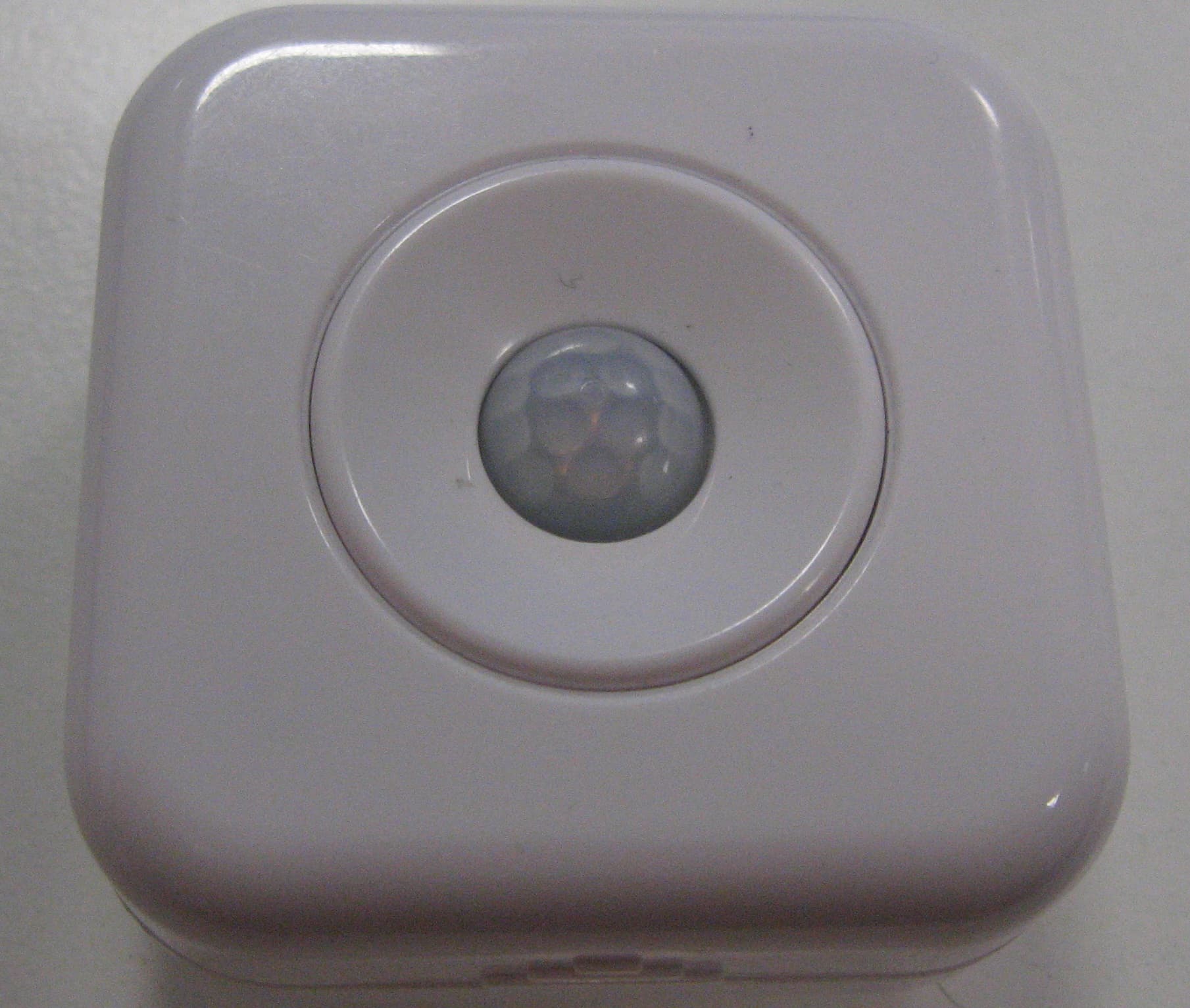
WJHMD12
May 30, 2012Wireless Motion Detector
Equipment Class
DTS - Digital Transmission System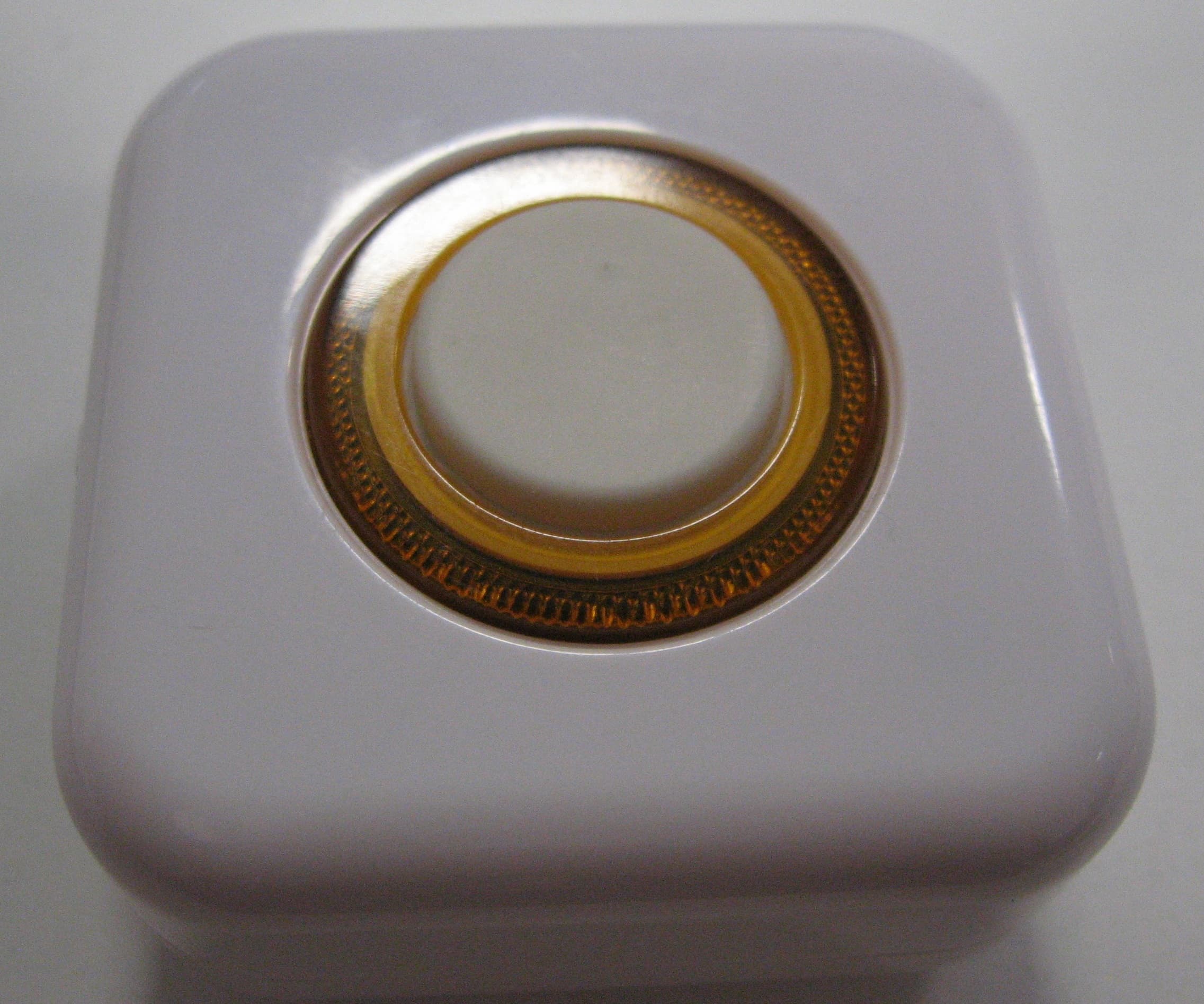
WJHB12
May 29, 2012Wireless Button
Equipment Class
DTS - Digital Transmission System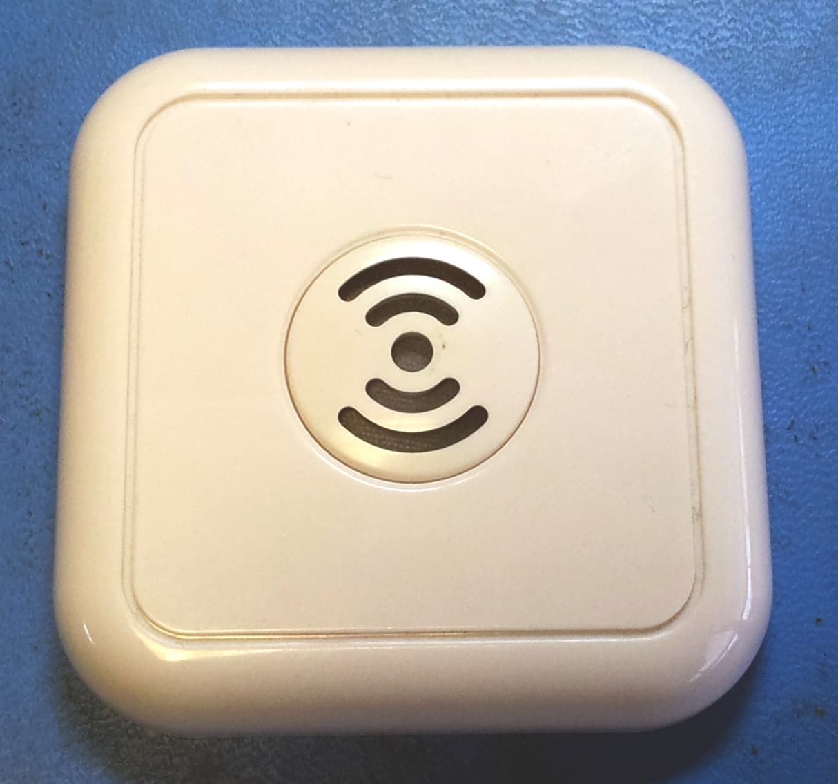
WJHNH11
Jul 28, 2011HUB310
Equipment Class
DTS - Digital Transmission System