WJLHT-4Handsfree Car Kit
Molex CVS Bochum GmbH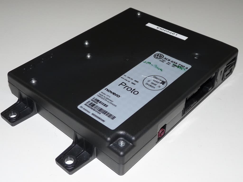
Click to zoom
Application Details
- Equipment Class
- PCB - PCS Licensed Transmitter
- Date of Grant
- Apr 11, 2010
- Application Purpose
- Original Equipment
- Date of Application
- Apr 08, 2010
- Equipment Note
- Handsfree Car Kit
- Frequency Range
- 1850.20000000 - 1909.80000000
- Company
- Molex CVS Bochum GmbH
- Country
- Germany
Documents & Files
Document Text
Text extracted from the exhibit documents filed with the FCC. Open a document above to read the original.
Users Manual
Operating manual Mobile telephone provision ENTWURF Description of symbols Refers you to a section within a chapter which contains important information and safety notes that should always be observed. Indicates that the section will continue on the next page. Indicates the end of a section. Indicates situations when the vehicle must be stopped as quickly as possible. ® Indicates a registered trademark. However, the absence of this symbol does not constitute a waiver of the rights concerning any term. Symbols like this refer you to warnings within the same section or on a given page. They draw your attention to possible risks of accident or injury and let you know how these can be avoided. Cross-reference to information about possible damage to your vehicle within the same section or on a given page. Da nger Texts with this symbol indicate dangerous situations which lead to fatal or severe injuries if you do not observe the warning. Wa rning Texts with this symbol indicate dangerous situations which could lead to fatal or severe injuries if you do not observe the warning. Ca ution Texts with this symbol indicate dangerous situations which could lead to slight or severe injuries if you do not observe the warning. No tice Texts with this symbol indicate situations which could cause vehicle damage if you do not observe the warning. Texts with this symbol contain additional information on the protection of the environment. ENTWURF Texts with this symbol contain additional information. ENTWURF Volkswagen AG works continuously to develop and further improve all models. Please appreciate that we must therefore reserve the right to alter any part of the vehicle and its equipment or technical specifica- tions at any time. The data provided concerning scope of delivery, appearance, performance, dimensions, weights, fuel consumption, standards and vehicle functions are all correct at the time of going to print. Some of the equipment described might not yet be available in vehicles (information can be provided by your local Volkswagen dealership), and some equipment may not be available in certain countries. No legal commitment can be derived from the information, illustrations or descriptions in this manual. No part of this manual may be reprinted, reproduced or translated without the written permission of Volkswagen AG. All rights under the laws of copyright are expressly reserved by Volkswagen AG. Subject to alteration and amendment. Printed in Germany. © 2010 Volkswagen AG This paper was bleached without the use of chlorine. ENTWURF Operating manual: Mobile telephone provision Print status: 14.01.2010 English: 01.2010 Art.-Nr.: 102.5R8.MTV.20 ENTWURF ENTWURF Operating manual Contents 7 Contents Thank you for choosing Volkswagen..............................................9 About this manual...........................................................................11 Introduction......................................................................................13 The different mobile telephone provisions................................................................. 13 Safety notes .............................................................................................................. 14 General information................................................................................................... 15 Basic information on use................................................................18 Controls.....................................................................................................................18 Important steps for the use of the mobile telephone provision .................................. 23 Operating the mobile telephone provision................................................................. 24 PREMIUM mobile telephone provision..........................................27 Getting started .......................................................................................................... 27 Using the telephone .................................................................................................. 31 Voice control ............................................................................................................. 34 Telephone menu....................................................................................................... 37 Abbreviations used.........................................................................47 Index.................................................................................................49 ENTWURF ENTWURF Operating manual Thank you for choosing Volkswagen 9 Thank you for choosing Volkswagen The mobile telephone provision supplied with your vehicle allows convenient telephone use in the vehicle and offers a wide range of features that will certainly be useful to you during everyday driving. Before using your mobile telephone provision for the first time, please read and observe the information in this operating manual. It will quickly help you to become familiar with your mo- bile telephone provision and all of its functions as well as making you aware of dangers to yourself and others and of how these dangers can be avoided. If you have any further questions about your vehicle, or you think that the vehicle wallet has not cov- ered everything, please get in touch with your Volkswagen dealership. They will always be happy to deal with your questions, suggestions or problems. We hope you get great driving pleasure from your vehicle. Happy motoring. Volkswagen AG ENTWURF ENTWURF Operating manual About this manual 11 About this manual An alphabetical index is included at the end of this manual. A list of abbreviations with explanations of abbreviations and terms is given at the end of this manual. Directions and positions (e.g. right, left, front, rear) are normally relative to the vehicle's direction of travel. Illustrations help with orientation and should be regar…
Text truncated - open the document above for the full version.
Cover Letter(s)
Request for confidentiality CONFIDENTIALITY REQUEST for FCC-ID: WJLHT-4 To Whom It May Concern: In accordance with provisions of Section 0.457(d) of the Commission’s Rules and Section 552(b)(4) of the Freedom of Information Act, we request permanent confidentiality for transmitter’s exhibits, which contain: Operation Description Block Diagram Schematic Diagram Tune up procedure These exhibits contain proprietary, confidential and trade secrets material, which would not be routinely made available for public inspection. Also, in accordance with FCC Public DA 04-1705, we request short-term confidentiality for exhibits, which contain: Internal Photographs User Manual These exhibits contain pre-market information, which could give our competitors unfair advantage should this information be released before this product is actually introduced into the common marketplace Do not hesitate to contact me if you have any additional questions. Company : 7 layers AG Borsigstarsse 11 40880 Ratingen, Germany Point of contact : Mr. Holger Leutfeld Signed, 7 layers AG, (authorized Agent)
Cover Letter(s)
Copyright 2009 novero. All rights reserved. novero GmbH Rensingstrasse 15, 44807 Bochum Germany Tel.: +49 234 51668 0 Fax: +49 234 51668 4880 January, 20 th , 2010 Federal Communications Commission Authorization & Evaluation Division, 7435 Oakland Mills Road, Columbia, MD. 21046 LETTER OF AGENCY AUTHORISATION We, the undersigned, hereby authorize the company 7 layers AG, 40880 Ratingen, Germany, contact person Holger Leutfeld to act on our behalf in all matters relating to application for equipment authorization (FCC ID: WJLHT-4), including the signing of all documents relating to these matters. We also hereby certify that no party to the application authorized hereunder is subject to the denial of benefits, including FCC benefits, pursuant to Section 5301 of the Anti-Drug Abuse of 1988, 21 U.S.C.853(a). This agreement expires one year from the current date. novero GmbH, Bochum, Germany Robert Müller Product Certification Manager
ID Label/Location Info
HT-4 Type Label and Type Label Location
RF Exposure Info
7 layers AG Aufsichtsratsvorsitzenderh Registergerichth registered in: Borsigstrasse 11 Chairman of the Supervisory Board: Düsseldorf, HRB 44096 40880 Ratingen, Germany Markus Becker USt-IdNr h VAT No.: Phone: +49 (0) 2102 749 0 Vorstandh Board: DE 203159652 Fax: +49 (0) 2102 749 350 Dr. Hermann Buitkamp TAX No. 147/5869/0385 www.7Layers.com Wilfried Klassmann Holger Leutfeld 12.04.2010 Phone +49 (0) 2102 749 317 Fax +49 (0) 2102 749 350 Maximum Permissible Exposure for product: Novero HT-4, FCC ID: WJLHT-4 Dear Ms. Baufeld, please find our Maximum Permissible Exposure calculations for the Novero HT-4 Best Regards Holger Leutfeld (Project manager) Novero GmbH Ms. Ines Baufeld Rensingstr. 15 44807 Bochum MDE_NOVER_0902 - 2 - Maximum Permissible Exposure (as specified in Table 1B of 47 CFR 1.1310 – Limits for Maximum Permissible Exposure (MPE), Limits for General Population/Uncontrolled Exposure) Frequency range (MHz) Power density (mW/cm²) 300 – 1,500 f/1500 1,500 – 100,000 1.0 Calculations 850 MHz band Maximum output power at antenna input terminal: 31.65 dBm Maximum output power at antenna input terminal under consideration of the duty cycle effect: 29.61 dBm. Prediction distance R: 20 cm Prediction frequency: 824,20 MHz MPE limit S: 0.5495 mW/cm² Equation OET bulletin 65, page 18, edition 97-01: S = P*G / (4πR²) S = power density P = power input to the antenna G = power gain of the antenna in the direction of interest relative to an isotropic radiator R = distance to the centre of radiation of the antenna Maximum permissible antenna gain: 4.80 dBi Prediction The maximum allowed MPE value of 0.5495 mW/cm²will be reached in a distance of 20 cm in case that an antenna with an antenna gain of 4.80 dBi would be used. This means that the power density levels in a distance of 20 cm are in accordance with the FCC regulations as long as the used antenna has a gain below 4.80 dBi. The average values in the FCC test report were determined over the transmit period only. For MS class 32 a duty cycle of -2.04dBm has to be considered in the calculation. - 3 - Calculations 1900 MHz band Maximum output power at antenna input terminal: 29.19 dBm Maximum output power at antenna input terminal under consideration of the duty cycle effect: 27.15 dBm. Prediction distance R: 20 cm Prediction frequency: 1850,20 MHz MPE limit S: 1 mW/cm² Equation OET bulletin 65, page 18, edition 97-01: S = P*G / (4πR²) S = power density P = power input to the antenna G = power gain of the antenna in the direction of interest relative to an isotropic radiator R = distance to the centre of radiation of the antenna Maximum permissible antenna gain: 9.86 dBi Maximum permissible antenna gain for mobile / portable stations 3.43 dBi Prediction The maximum allowed MPE value of 1 mW/cm² will be reached in a distance of 20 cm in case that an antenna with an antenna gain of 9.86 dBi would be used. This means that the power density levels in a distance of 20 cm are in accordance with the FCC regulations as long as the used antenna has a gain below 9.86 dBi. Considering the max output power of 2 Watts EIRP (FCC §24.235) for mobile / portable stations the maximum antenna gain is 3.43 dBi, which is below 9.86 dBi and in accordance to the FCC regulations. The average values in the FCC test report were determined over the transmit period only. For MS class 32 a duty cycle of -2.04dBm has to be considered in the calculation.
Test Report
Final Report on HT-4 MDE_NOVER_0902_FCCaReport Reference: November 20, 2009Date: Test Laboratory: 7 layer s AG Borsigstr. 11 DAT-P-192/99-01 40880 R atingen Germany Note: The following test results relate only to the devices specified in this document. This report shall not be reproduced in parts with out th e written approval of the t est l aboratory. 7 layers AG Au fsic hts rat svorsi tze nder h Registergerichth registered in: Bo rs igst ra sse 1 1 Chair man o f t he S up ervis or y B o ard : Düsseldorf, HRB 44096 408 80 Rat ing en, G erma ny Marku s B ecker US t-Id Nr h VAT No.: Phone: +49 (0) 2102 749 0 Vo rst andh Board: DE 203 159 652 Fa x: +4 9 (0) 21 02 7 49 350 Dr. Hermann Bu it ka mp TAX N o. 14 7/58 69/0 385 www.7La yers.com Wilfried Klassmann Reference: MDE_NOVER_0902_FCCa 2.2Detailed Description of OUT Samples Sample : e01 OUT IdentifierHT-4 Sample DescriptionGSM / UMTS HW StatusX07 SW StatusX060 Date of Receipt2009/09/01 Low VoltageLow Temp.9.5 V-30 °C High Temp.High Voltage16 V70 °C Normal Temp.Nominal Voltage13.2 V20 °C Sample : g01 OUT IdentifierHT-4 Sample DescriptionGSM / UMTS HW StatusX07 SW StatusX060 Date of Receipt2009/09/01 Low VoltageLow Temp.9.5 V-30 °C High Temp.High Voltage16 V70 °C Normal Temp.Nominal Voltage13.2 V20 °C 2.3OUT Features Features for OUT: HT-4 Allowed ValuesDesignationDescriptionSupported Value(s) Features for scope: FCC_v2 BTEUT supports Bluetooth data rate of 1 Mbps with GFSK modulation in the band 2400 MHz - 2483.5 MHz EDGE850EUT supports EDGE in the band 824 MHz - 849 MHz EDGE1900EUT supports EDGE in the band 1850 MHz - 1910 MHz EDR2EUT supports Bluetooth using data rate of 2 Mbps with PI/4 DQPSK modulation in the band 2400 MHz - 2483.5 MHz EDR3EUT supports Bluetooth using data rate of 3 Mbps with 8DPSK modulation in the band 2400 MHz - 2483.5 MHz FDD5EUT supports UMTS FDD5 in the band 824 MHz - 849 MHz GSM850EUT supports GSM850 band 824MHz - 849MHz PantCpermanent fixed antenna connector, which may be built-in, designed as an indispensable part of the equipment PCS1900EUT supports PCS1900 band 1850MHz - 1910MHz Page 4 of 95 Reference: MDE_NOVER_0902_FCCa 2.4Setups used for Testing For each setup a relation is given to determine if and which samples and auxiliary equipment is used. The left side list all OUT samples and the right side lists all auxiliary equipment for the given setup. Sample No.Sample DescriptionAE No.AE Description Setup No.List of OUT samplesList of auxiliary equipment E01 e01GSM / UMTSSample: G01 AE 01external Antennag01GSM / UMTSSample: 3Results 3.1General Available at the test laboratory. The results of the inspection are described on the following pages, where 'Conformity' or 'Passed' means that the certification criteria were verified and that the tested device is conform to the applied standard. In cases where 'Declaration' is printed, the required documents are available in the manufacturers product documentation. In cases where 'not applicable' is printed, the test case requirements are not relevant to the specific equipment implementation. Documentation of tested devices: Interpretation of the test results: 3.2List of the Applicable Body (Body for Scope: FCC_v2) DesignationDescription Part 22, Subpart H - Cellular Radiotelephone ServiceFCC47CFRChIPART22PUBLIC MOBILE SERVICES 3.3List of Test Specification Test Specification:FCC part 2 and 22 Date / Version2009/03/26 Version: 10-1-08 Edition Title:PART 2 - GENERAL RULES AND REGULATIONS PART 22 - PUBLIC MOBILE SERVICES Page 5 of 95 Reference: MDE_NOVER_0902_FCCa 3.4Summary Test Case Identifier / Name SetupDate of TestResultCatTest (condition)Ref. Lab 22.1 RF Power Output §2.1046, §22.913 22.1; Frequency Band = 850, Mode = EDGE, Channel = 128, Frequency = 824.2MHz, Method = conducted -2009/11/03G01Lab 2Passed 22.1; Frequency Band = 850, Mode = EDGE, Channel = 128, Frequency = 824.2MHz, Method = radiated -2009/10/30G01Lab 1Passed 22.1; Frequency Band = 850, Mode = EDGE, Channel = 190, Frequency = 836.6MHz, Method = conducted -2009/11/03G01Lab 2Passed 22.1; Frequency Band = 850, Mode = EDGE, Channel = 190, Frequency = 836.6MHz, Method = radiated -2009/10/30G01Lab 1Passed 22.1; Frequency Band = 850, Mode = EDGE, Channel = 251, Frequency = 848.8MHz, Method = conducted -2009/11/03G01Lab 2Passed 22.1; Frequency Band = 850, Mode = EDGE, Channel = 251, Frequency = 848.8MHz, Method = radiated -2009/10/30G01Lab 1Passed 22.1; Frequency Band = 850, Mode = GSM, Channel = 128, Frequency = 824.2MHz, Method = conducted -2009/11/03G01Lab 2Passed 22.1; Frequency Band = 850, Mode = GSM, Channel = 128, Frequency = 824.2MHz, Method = radiated -2009/10/30G01Lab 1Passed 22.1; Frequency Band = 850, Mode = GSM, Channel = 190, Frequency = 836.6MHz, Method = conducted -2009/11/03G01Lab 2Passed 22.1; Frequency Band = 850, Mode = GSM, Channel = 190, Frequency = 836.6MHz, Method = radiated -2009/10/30G01Lab 1Passed 22.1; Frequency Band = 850, Mode = GSM, Channel = 251, Frequency = 848.8MHz, Method = conducted -2009/11/03G01Lab 2Passed 22.1; Frequency Band = 850, Mode = GSM, Channel = 251, Frequency = 848.8MHz, Method = radiated -2009/10/30G01Lab 1Passed 22.1; Frequency Band = FDD5, Mode = W- CDMA, Channel = 4132, Frequency = 826.4MHz, Method = conducted -2009/11/03G01Lab 2Passed 22.1; Frequency Band = FDD5, Mode = W- CDMA, Channel = 4132, Frequency = 826.4MHz, Method = radiated -2009/10/30G01Lab 1Passed 22.1; Frequency Band = FDD5, Mode = W- CDMA, Channel = 4183, Frequency = 836.6MHz, Method = conducted -2009/11/03G01Lab 2Passed 22.1; Frequency Band = FDD5, Mode = W- CDMA, Channel = 4183, Frequency = 836.6MHz, Method = radiated -2009/10/30G01Lab 1Passed 22.1; Frequency Band = FDD5, Mode = W- CDMA, Channel = 4233, Frequency = 846.6MHz, Method = conducted -2009/11/03G01Lab 2Passed 22.1; Frequency Band = FDD5, Mode = W- CDMA, Channel = 4233, Frequency = 846.6MHz, Method = radiated -2009/10/30G01Lab 1Passed Page 6 of 95 Reference: MDE_NOVER_0902_FCCa Test Case Identifier / Name SetupDate of TestResult…
Text truncated - open the document above for the full version.
Test Report
Final Report on HT-4 MDE_NOVER_0902_FCCbReport Reference: November 19, 2009Date: Test Laboratory: 7 layer s AG Borsigstr. 11 DAT-P-192/99-01 40880 R atingen Germany Note: The following test results relate only to the devices specified in this document. This report shall not be reproduced in parts with out th e written approval of the t est l aboratory. 7 layers AG Au fsic hts rat svorsi tze nder h Registergerichth registered in: Bo rs igst ra sse 1 1 Chair man o f t he S up ervis or y B o ard : Düsseldorf, HRB 44096 408 80 Rat ing en, G erma ny Marku s B ecker US t-Id Nr h VAT No.: Phone: +49 (0) 2102 749 0 Vo rst andh Board: DE 203 159 652 Fa x: +4 9 (0) 21 02 7 49 350 Dr. Hermann Bu it ka mp TAX N o. 14 7/58 69/0 385 www.7La yers.com Wilfried Klassmann Reference: MDE_NOVER_0902_FCCb 2.2Detailed Description of OUT Samples Sample : e01 OUT IdentifierHT-4 Sample DescriptionGSM / UMTS HW StatusX07 SW StatusX060 Date of Receipt2009/09/01 Low VoltageLow Temp.9.5 V-30 °C High Temp.High Voltage16 V70 °C Normal Temp.Nominal Voltage13.2 V20 °C Sample : g01 OUT IdentifierHT-4 Sample DescriptionGSM / UMTS HW StatusX07 SW StatusX060 Date of Receipt2009/09/01 Low VoltageLow Temp.9.5 V-30 °C High Temp.High Voltage16 V70 °C Normal Temp.Nominal Voltage13.2 V20 °C 2.3OUT Features Features for OUT: HT-4 Allowed ValuesDesignationDescriptionSupported Value(s) Features for scope: FCC_v2 BTEUT supports Bluetooth data rate of 1 Mbps with GFSK modulation in the band 2400 MHz - 2483.5 MHz EDGE850EUT supports EDGE in the band 824 MHz - 849 MHz EDGE1900EUT supports EDGE in the band 1850 MHz - 1910 MHz EDR2EUT supports Bluetooth using data rate of 2 Mbps with PI/4 DQPSK modulation in the band 2400 MHz - 2483.5 MHz EDR3EUT supports Bluetooth using data rate of 3 Mbps with 8DPSK modulation in the band 2400 MHz - 2483.5 MHz FDD5EUT supports UMTS FDD5 in the band 824 MHz - 849 MHz GSM850EUT supports GSM850 band 824MHz - 849MHz PantCpermanent fixed antenna connector, which may be built-in, designed as an indispensable part of the equipment PCS1900EUT supports PCS1900 band 1850MHz - 1910MHz Page 4 of 74 Reference: MDE_NOVER_0902_FCCb 2.4Setups used for Testing For each setup a relation is given to determine if and which samples and auxiliary equipment is used. The left side list all OUT samples and the right side lists all auxiliary equipment for the given setup. Sample No.Sample DescriptionAE No.AE Description Setup No.List of OUT samplesList of auxiliary equipment E01 e01GSM / UMTSSample: G01 AE 01external Antennag01GSM / UMTSSample: 3Results 3.1General Available at the test laboratory. The results of the inspection are described on the following pages, where 'Conformity' or 'Passed' means that the certification criteria were verified and that the tested device is conform to the applied standard. In cases where 'Declaration' is printed, the required documents are available in the manufacturers product documentation. In cases where 'not applicable' is printed, the test case requirements are not relevant to the specific equipment implementation. Documentation of tested devices: Interpretation of the test results: 3.2List of the Applicable Body (Body for Scope: FCC_v2) DesignationDescription Part 24, Subpart E - Broadband PCSFCC47CFRChIPART24PERSONAL COMMUNICATIONS SERVICES 3.3List of Test Specification Test Specification:FCC part 2 and 24 Date / Version2009/03/26 Version: 10-1-08 Edition Title:PART 2 - GENERAL RULES AND REGULATIONS PART 24 - PERSONAL COMMUNICATIONS SERVICES Page 5 of 74 Reference: MDE_NOVER_0902_FCCb 3.4Summary Test Case Identifier / Name SetupDate of TestResultCatTest (condition)Ref. Lab 24.1 RF Power Output §2.1046, §24.232 24.1; Frequency Band = 1900, Mode = EDGE, Channel = 512, Frequency = 1850.2MHz, Method = conducted -2009/11/03G01Lab 2Passed 24.1; Frequency Band = 1900, Mode = EDGE, Channel = 512, Frequency = 1850.2MHz, Method = radiated -2009/10/30G01Lab 1Passed 24.1; Frequency Band = 1900, Mode = EDGE, Channel = 661, Frequency = 1880.0MHz, Method = conducted -2009/11/03G01Lab 2Passed 24.1; Frequency Band = 1900, Mode = EDGE, Channel = 661, Frequency = 1880.0MHz, Method = radiated -2009/10/30G01Lab 1Passed 24.1; Frequency Band = 1900, Mode = EDGE, Channel = 810, Frequency = 1909.8MHz, Method = conducted -2009/11/03G01Lab 2Passed 24.1; Frequency Band = 1900, Mode = EDGE, Channel = 810, Frequency = 1909.8MHz, Method = radiated -2009/10/30G01Lab 1Passed 24.1; Frequency Band = 1900, Mode = GSM, Channel = 512, Frequency = 1850.2MHz, Method = conducted -2009/11/03G01Lab 2Passed 24.1; Frequency Band = 1900, Mode = GSM, Channel = 512, Frequency = 1850.2MHz, Method = radiated -2009/10/30G01Lab 1Passed 24.1; Frequency Band = 1900, Mode = GSM, Channel = 661, Frequency = 1880.0MHz, Method = conducted -2009/11/03G01Lab 2Passed 24.1; Frequency Band = 1900, Mode = GSM, Channel = 661, Frequency = 1880.0MHz, Method = radiated -2009/10/30G01Lab 1Passed 24.1; Frequency Band = 1900, Mode = GSM, Channel = 810, Frequency = 1909.8MHz, Method = conducted -2009/11/03G01Lab 2Passed 24.1; Frequency Band = 1900, Mode = GSM, Channel = 810, Frequency = 1909.8MHz, Method = radiated -2009/10/30G01Lab 1Passed 24.2 Frequency stability §2.1055, §24.235 24.2; Frequency Band = 1900, Mode = EDGE, Channel = 661, Frequency = 1880.0MHz -2009/11/04E01Lab 2Passed 24.2; Frequency Band = 1900, Mode = GSM, Channel = 661, Frequency = 1880.0MHz -2009/10/26E01Lab 2Passed 24.3 Spurious emissions at antenna terminals §2.1051, §24.238 24.3; Frequency Band = 1900, Mode = EDGE, Channel = 512, Frequency = 1850.2MHz -2009/11/03E01Lab 2Passed 24.3; Frequency Band = 1900, Mode = EDGE, Channel = 661, Frequency = 1880.0MHz -2009/11/03E01 Lab 2Passed 24.3; Frequency Band = 1900, Mode = EDGE, Channel = 810, Frequency = 1909.8MHz -2009/11/03E01Lab 2Passed 24.3; Frequency Band = 1900, Mode = GSM, Channel = 512, Frequency = 1850.2MHz -2009/10/23E01Lab 2Passed 24.3; Frequency Band = 1900, Mode = GSM, Channel = 661, Frequency = 1880.0MHz -2009/10/23E01Lab 2Pass…
Text truncated - open the document above for the full version.
Test Setup Photos
0 Photo Report Detailed photos of the OUT are declared as confidential. Photo 1: Test setup for radiated measurements (Enclosure, below 30 MHz) Photo 2: Test setup for radiated measurements (Enclosure, 30 MHz to 1 GHz) Photo 3: Setup of the OUT the measurements (Enclosure, 30 MHz to 1 GHz) Photo 4: Test setup for radiated measurements (Enclosure, above 1 GHz)
Contact Information
Applicant
Robert Mueller(Product Certification Manager)
Test Firm
7layers AGRobert Machulec
Technical Specifications
| # | Rule Parts | Frequency Range | Power Output | Emission | Tolerance |
|---|---|---|---|---|---|
| 5 | 24E | 1.85 GHz - 1.91 GHz | 724.00 mW | 300KG7W | 2.5 ppm |
Other Applications from Molex CVS Bochum GmbH
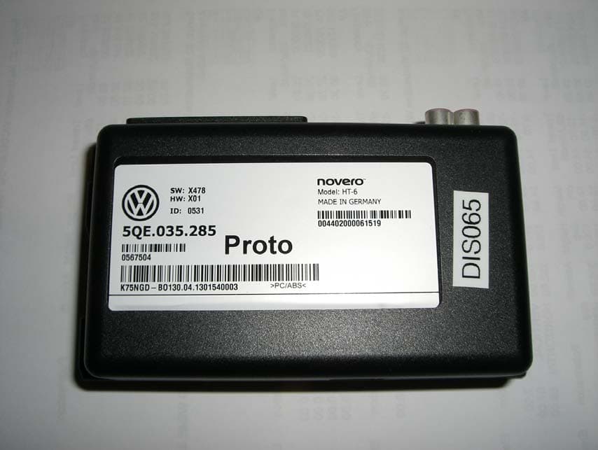
WJLHT-6G
Jul 14, 2013On Board Vehicle Connectivity Unit
Equipment Class
PCB - PCS Licensed Transmitter
WJLHT-6C
Nov 18, 2012On Board Vehicle Connectivity Unit
Equipment Class
PCB - PCS Licensed Transmitter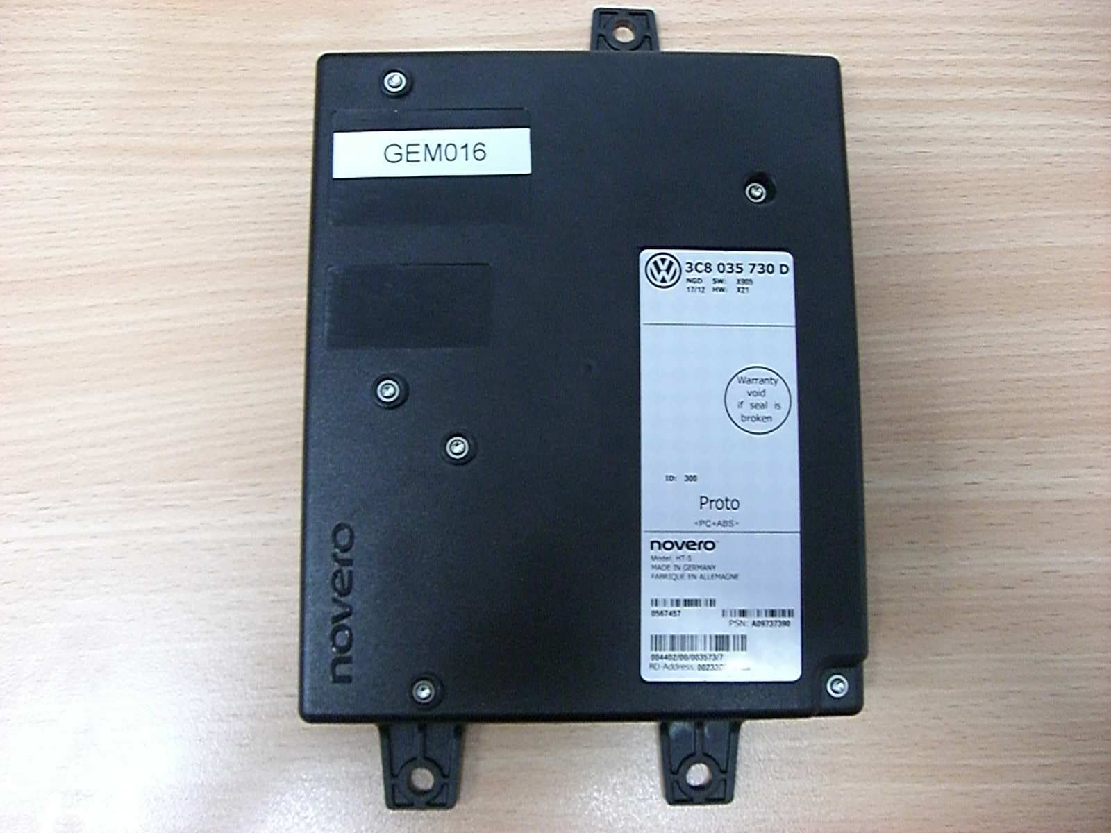
WJLHT-5
Aug 28, 2012Hands-Free Unit with Bluetooth, WLAN and GSM/WCDMA, HT-5
Equipment Class
DSS - Part 15 Spread Spectrum Transmitter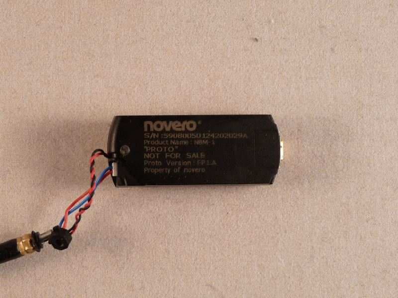
WJLNBM-1
Aug 11, 2010Bluetooth� V2.1 Module for Headset Applications
Equipment Class
DSS - Part 15 Spread Spectrum Transmitter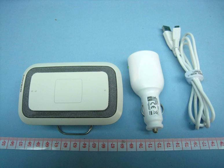
WJLNHFP-1
Dec 21, 2009TheTalkyOne
Equipment Class
DSS - Part 15 Spread Spectrum Transmitter