WL9ETC62D2.4GHz Radio Control system
ShenZhen ART-TECH R/C Hobby Co., Ltd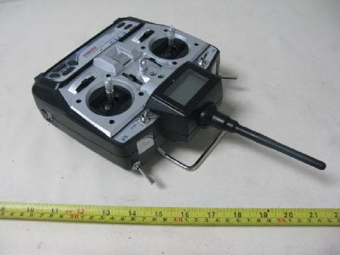
Click to zoom
Application Details
- Equipment Class
- DTS - Digital Transmission System
- Date of Grant
- Jan 04, 2010
- Application Purpose
- Original Equipment
- Date of Application
- Jan 04, 2010
- Equipment Note
- 2.4GHz Radio Control system
- Frequency Range
- 2402.00000000 - 2474.00000000
- Country
- China
Documents & Files
Document Text
Text extracted from the exhibit documents filed with the FCC. Open a document above to read the original.
Users Manual
Operating Manual LCD DIGITAL PROPORTIONAL RADIO CONTROL SYSTEM ETC62D-2.4GHz Catalog Notification before Using 05 Notice for use 04 Contents 04 Specifications 04 Transmitter particular introductine 06 Menu introduction 07 Other function of the transmitter 11 Receiver 12 Electronic speed controler 10 Operation for transmitter and servo 13 Flow list 17 Function of Transmitter 0 3 Charge method of battery 16 www.art-tech.com 02 The process of frequency bind for 2.4GHz R/C system 15 Adjust order 14 Function of Transmitter ETC62D-2.4GHz is a newly developed 6 channel proportional transmitter. The latest developed product of ART-TECH RC Hobby Corporation. The 2.4GHz RC system uses digital frequency-hopping technology; it has enormous advantage compared with traditional system: no crystal, no frequency interference, short antenna length and low power consumption. 1. Flying time display: less than 1 minute seconds showed, more than 1 minute minutes showed. 2. Supply voltage display and low voltage alarm function: When the battery voltage is lower than 8.5V, the red LED flashes, and alarm. 3. Channel output reverse set. 4.5 kinds of aircraft modes to choose, 12 independent aircraft data storage and call. 5.Mode I and mode II exchange. 6. Throttle protection: in order to avoid danger of starting the motor of a sudden, when throttle hold switch is turned on, throttle output value is the minimum. When boot, for various reasons (location of the assembly, curve setup), throttle output value is not the minimum, the red LED flashes and alarm, as shown in the figure. The throttle lose automatically locked out for a minimum value, when the transmitter adjustment is appropriate (that is, the throttle output is the smallest), the transmitter is unlocked. 7.Ch1 ch2 ch4 DR (Dual Rate) setting. 8.Ch1 ch2 ch4 EXP(exponential curve) setting. 9.All channel EPA (end of the process) setting. 10. Ch5 two-state setting (gyroscope sensitivity setting for helicopters, landing gear set up for fixed- wing planes). 11. Ch3 ch6 general and 3D mode curve set for general helicopters and CCPM helicopters 12. 4 groups channel mixing control 13. All channel output dynamic display 14. All channel mid-point regulation 15. Restore the factory settings 16. Ch1 ~ Ch6 auxiliary fine-tuning settings www.art-tech.com 03 Thanks for purchasing ETC62D-2.4GHz radio control set. For safe use, please read this manual before using carefully. Any damage or loss to radio control set and model due to inproper use will not be shouldered by Art-Tech. www.art-tech.com 04 Servo: AS-100(9 g) 3pcs Speed controller: ESC-30A 1pcs Bettery packs: 9.6V/Ni-MH 1pcs Charger: 1pcs Specifications Number of channels: 6 Charging jack: yes 3D switch: yes Power supply: 12 V (1.5V * 8AA batteries) We do not offer servo, speed controller, battery or changer with the radio control system . Users can buy as spare parts. Transmitter: ETC62D-2.4GHz 1pcs Receiver:ER62-2.4GHz 1p c s Simulator cable:1pcs Belt:1pcs Manual:1pcs CD:1pcs Contents: Voltage Display: LCD Color: Black Antenna length: 15 cm Using occasions: aircraft, helicopters Certification: FCC, CE, RoHS Notice for use Please do not fly in the rain or strong wind. The water can sink into the transmitter which can cause out of control,leading to crash. Pleas note before using, test the radio set first and any change to the radio set or model can cause crash. Please do not fly near housing, road,airport or power line The transmitter can not work properly if the frequency bind button is pressed down neglectfully. In this case, The transmitter and the receiver must be bind again. More details , Please refer to the process of frequency bind for 2.4 GHz R/C system. Please do not turn on several RC devices and bind them at the same time, bind only one set of RC device at one time. The RC device should not be stay in bind state for a long time. Storage note Show Logo Meanings WARNING CAUTION Indications of Special signs Attention Notification before Using Please pay more attention to signs in this manual and safety while using ▲Please do not place the radio control set in the below situation: hot or cold(60°Cabove or -10°Cbelow) under the sunshine long time moist condition dusty place vibration condition ▲long time without using, please pick up batteries from the bay and store in the dry condition. ▲It is forbidden to clean the radio control set with chemical solvent such as acetone ▲The over used dry batteries can not be dispatched anywhere. That should be stored in a non-metal tool and dispatched by environment-protection department. ▲ It is strongly recommended to use chargeable battery for the transmitter with the hope of environment-protection and cost-reducing. While opening the transmitter,the joystick for throttle shoule be on idle;only opening the transmiiter can connect the power to model. In order to close the transmitter, the joystick for throttle should be o nidle . Disconnect t h e power of model,and close the transmitter. The propeller may c ause d amageif im proper operation. Stop the motor while transmitter adjustment. Please pay attention to the motor during adjustment.It is better to use transmitter ,receiver etc,together from ART-TECH. Please do not do any change to transmitter, otherwise it can affect transmitter`s function. I improper operation may cause injury or hurt I improper operation may cause injury or hurt www.art-tech.com 05 www.art-tech.com 06 Transmitter particular introduce A:Antenna B:LCD(Liquid Crystal Display) 1)display battery voltage of transmitter 2)display whether the channels are reversed 3)display flying time 4)display menus 5) Display lock or unlock state Display area 1)function display area 2)channels direction display area 3)data display area 4)option number display area C:Throttle hold switch D:Ch5 switch This switch is for Ch5 that can be used for aerial camera, collapsible landing gear and shift between gyro mode and gyro gain, etc. E:3D switch F:D/R switch G:Indicator LED…
Text truncated - open the document above for the full version.
External Photos
Neutron Engineering Inc. Project No.: 0908C110 Page 2 of 8 0908C110 0908C110 Neutron Engineering Inc. Project No.: 0908C110 Page 2 of 8 0908C110 0908C110
ID Label/Location Info
1622 FCC ID: WL9ETC62D 名称:ETC62D-2.4G发射机背部通用贴纸 尺寸:39.5x46.9mm 材质:拉丝铝,灰色为铝底,跟普通C型材质,刀模一样 ShenZhen ART-TECH R/C Hobby Co., Ltd. Model No: ETC62D-2.4GHz 2.4GHz Radio Control system Input:12V 200mA Output: 10mW 1622 FCC ID: WL9ETC62D ShenZhen ART-TECH R/C Hobby Co., Ltd. Model No: ETC62D-2.4GHz 2.4GHz Radio Control system Input:12V 200mA Output: 10mW 8 4 m m 59.5mm
Internal Photos
Neutron Engineering Inc. Project No.: 0908C110 Page 3 of 8 0908C110 0908C110 Neutron Engineering Inc. Project No.: 0908C110 Page 3 of 8 0908C110 0908C110 Neutron Engineering Inc. Project No.: 0908C110 Page 4 of 8 0908C110 0908C110 Neutron Engineering Inc. Project No.: 0908C110 Page 4 of 8 0908C110 0908C110 Neutron Engineering Inc. Project No.: 0908C110 Page 5 of 8 0908C110 0908C110 Neutron Engineering Inc. Project No.: 0908C110 Page 5 of 8 0908C110 0908C110 Neutron Engineering Inc. Project No.: 0908C110 Page 6 of 8 0908C110 Neutron Engineering Inc. Project No.: 0908C110 Page 7 of 8 0908C110 0908C110 Neutron Engineering Inc. Project No.: 0908C110 Page 7 of 8 0908C110 0908C110 Neutron Engineering Inc. Project No.: 0908C110 Page 8 of 8 0908C110 0908C110 Neutron Engineering Inc. Project No.: 0908C110 Page 8 of 8 0908C110 0908C110
Test Report
Neutron Engineering Inc. Report No.: NEI-FCCP-1-0908C110 Page 2 of 53 Declaration Neutron represents to the client that testing is done in accordance with standard procedures as applicable and that test instruments used has been calibrated with the standards traceable to National Measurement Laboratory (NML) of R.O.C., or National Institute of Standards and Technology (NIST) of U.S.A. Neutron's reports apply only to the specific samples tested under conditions. It is manufacture’s responsibility to ensure that additional production units of this model are manufactured with the identical electrical and mechanical components. Neutron shall have no liability for any declarations, inferences o r generalizations drawn by the client or others from Neutron issued reports. Neutron’s reports must not be used by the client to claim product endorsement by the authorities or any agency of the Government. This report is the confidential property of the client. As a mutual protection to the clients, the public and Neutron-self, extracts from the test report shall not be reproduced except in full with Neutron’s authorized written approval. Neutron’s laboratory quality assurance procedures are in compliance with the ISO Guide 17025 requirements, and accredited by the conformity assessment authorities listed in this test report. Limitation For the use of the authority's logo is limited unless the Test Standard(s)/Scope(s)/Item(s) mentioned in this test report is (are) included in the conformity assessment authorities acceptance respective. Neutron Engineering Inc. Report No.: NEI-FCCP-1-0908C110 Page 3 of 53 Table of Contents Page 1 . CERTIFICATION 5 2 . SUMMARY OF TEST RESULTS 6 2.1 TEST FACILITY 7 2.2 MEASUREMENT UNCERTAINTY 7 3 . GENERAL INFORMATION 8 3.1 GENERAL DESCRIPTION OF EUT 8 3.2 DESCRIPTION OF TEST MODES 10 3.3 TABLE OF PARAMETERS OF TEXT SOFTWARE SETTING 11 3.4 BLOCK DIGRAM SHOWING THE CONFIGURATION OF SYSTEM TESTED 11 3.5 DESCRIPTION OF SUPPORT UNITS 12 4 . EMC EMISSION TEST 13 4.1 CONDUCTED EMISSION MEASUREMENT 13 4.1.1 POWER LINE CONDUCTED EMISSION LIMITS 13 4.1.2 MEASUREMENT INSTRUMENTS LIST AND SETTING 13 4.1.3 TEST PROCEDURE 14 4.1.4 DEVIATION FROM TEST STANDARD 14 4.1.5 TEST SETUP 14 4.1.6 EUT OPERATING CONDITIONS 14 4.1.7 TEST RESULTS 15 4.2 RADIATED EMISSION MEASUREMENT 16 4.2.1 RADIATED EMISSION LIMITS 16 4.2.2 MEASUREMENT INSTRUMENTS LIST ANS SETTING 17 4.2.3 TEST PROCEDURE 18 4.2.4 DEVIATION FROM TEST STANDARD 18 4.2.5 TEST SETUP 19 4.2.6 EUT OPERATING CONDITIONS 19 4.2.7 TEST RESULTS (BETWEEN30 – 1000 MHZ) 20 4.2.8 TEST RESULTS (ABOVE 1000 MHZ) 22 4.2.9 TEST RESULTS (RESTRICTED BANDS REQUIREMENTS) 34 5 . BANDWIDTH TEST 38 5.1 APPLIED PROCEDURES / LIMIT 38 5.1.1 MEASUREMENT INSTRUMENTS LIST 38 5.1.2 TEST PROCEDURE 38 5.1.3 DEVIATION FROM STANDARD 38 5.1.4 TEST SETUP 39 5.1.5 EUT OPERATION CONDITIONS 39 Neutron Engineering Inc. Report No.: NEI-FCCP-1-0908C110 Page 4 of 53 Table of Contents Page 5.1.6 TEST RESULTS 40 6 . PEAK OUTPUT POWER TEST 42 6.1 APPLIED PROCEDURES / LIMIT 42 6.1.1 MEASUREMENT INSTRUMENTS LIST 42 6.1.2 TEST PROCEDURE 42 6.1.3 DEVIATION FROM STANDARD 42 6.1.4 TEST SETUP 42 6.1.5 EUT OPERATION CONDITIONS 42 6.1.6 TEST RESULTS 43 7 . ANTENNA CONDUCTED SPURIOUS EMISSION 44 7.1 APPLIED PROCEDURES / LIMIT 44 7.1.1 MEASUREMENT INSTRUMENTS LIST 44 7.1.2 TEST PROCEDURE 44 7.1.3 DEVIATION FROM STANDARD 44 7.1.4 TEST SETUP 44 7.1.5 EUT OPERATION CONDITIONS 45 7.1.6 TEST RESULTS 46 8 . POWER SPECTRAL DENSITY TEST 48 8.1 APPLIED PROCEDURES / LIMIT 48 8.1.1 MEASUREMENT INSTRUMENTS LIST 48 8.1.2 TEST PROCEDURE 48 8.1.3 DEVIATION FROM STANDARD 48 8.1.4 TEST SETUP 48 8.1.5 EUT OPERATION CONDITIONS 48 8.1.6 TEST RESULTS 49 9 . RF EXPOSURE TEST 51 9.1 APPLIED PROCEDURES / LIMIT 51 9.1.1 MPE CALCULATION METHOD 51 9.1.2 DEVIATION FROM STANDARD 51 9.1.3 EUT OPERATION CONDITIONS 51 9.1.4 TEST RESULTS 52 10 . EUT TEST PHOTO 53 Neutron Engineering Inc. Report No.: NEI-FCCP-1-0908C110 Page 5 of 53 1. CERTIFICATION E q u i p m e n t : 2.4GHz Radio Control system Brand Name : ART-TECH; E-FLY Model Name : ETC62D-2.4GHz A p p l i c a n t : ShenZhen ART-TECH R/C Hobby Co., Ltd. F a c t o r y : ShenZhen ART-TECH R/C Hobby Co., Ltd. A d d r e s s : 3/F,No.1 Wanyelong Industrial Park,Liyuan Industrial Area, Tangtou Village, Shiyan Town, Baoan District, Shenzhen City, China Date of Test : Aug. 20, 2009 ~ Sep. 23, 2009 T e s t I t e m : ENGINEERING SAMPLE Standards : FCC Part15, Subpart C(15.247) / ANCI C63.4 : 2003 The above equipment has been tested and found compliance with the requirement of the relative standards by Neutron Engineering Inc. EMC Laboratory. The test data, data evaluation, and equipment configuration contained in our test report (Ref No. NEI-FCCP-1-0908C110) were obtained utilizing the test procedures, test instruments, test sites that has been accredited by the Authority of NVLAP and TAF according to the ISO-17025 quality assessment standard and technical standard(s). Neutron Engineering Inc. Report No.: NEI-FCCP-1-0908C110 Page 6 of 53 2. SUMMARY OF TEST RESULTS Test procedures according to the technical standards: FCC Part15 (15.247) , Subpart C Standard Section Test Item Judgment Remark 15.207 Conducted Emission - Note(2) 15.247 (c) Antenna conducted Spurious EmissionPASS 15.247 (a)(2) 6dB Bandwidth PASS 15.247 (b) Peak Output Power PASS 15.247 (c) Radiated Spurious Emission PASS 15.247 (d) Power Spectral Density PASS 15.203 Antenna Requirement PASS 1.1307 1.1310 2.1091 2.1093 RF Exposure Compliance PASS NOTE: (1)” N/A” denotes test is not applicable in this Test Report (2) The EUT use new battery Neutron Engineering Inc. Report No.: NEI-FCCP-1-0908C110 Page 7 of 53 2.1 TEST FACILITY The test facilities used to collect the test data in this report is C01/OS02 at the location of No.132-1, Lane 329, Sec. 2, Palian Road, Shijr City, Taipei, Taiwan. Neutron's test firm number is 95335 2.2 MEASUREMENT UNCERTAINTY The reported uncertainty of measurement y ± U,where expended unce…
Text truncated - open the document above for the full version.
Test Setup Photos
Neutron Engineering Inc. Report No.: NEI-FCCP-1-0908C110 Page 53 of 53 10. EUT TEST PHOTO Radiated Measurement Photos Neutron Engineering Inc. Report No.: NEI-FCCP-1-0908C110 Page 53 of 53 10. EUT TEST PHOTO Radiated Measurement Photos
Contact Information
Applicant
Jie Huang
Technical Contact
Neutron Engineering Inc.Cathy Wang
[email protected]+886-769-83183000
No.3,JinShaGang 1st Road,ShiXia,DaLang Town · Dongguan · China
Non-Technical Contact
Neutron Engineering Inc.Cathy Wang
[email protected]+886-769-83183000
Test Firm
NEUTRON ENGINEERING INC.Elaine Wang
Technical Specifications
| # | Rule Parts | Frequency Range | Power Output |
|---|---|---|---|
| 1 | 15C | 2.40 GHz - 2.47 GHz | 17.00 mW |
Other Applications from ShenZhen ART-TECH R/C Hobby Co., Ltd
WL9KT21
Jan 05, 20102.4GHz Radio Control system
Equipment Class
DTS - Digital Transmission System
WL9ETB4SP
Dec 07, 20092.4GHz Radio Control system
Equipment Class
DTS - Digital Transmission System