Text extracted from the exhibit documents filed with the FCC. Open a document above to read the original.
DSC Manual Content Operating controls and componentsP 2 How to use your MINOX DSCP 2 Charging the batteriesP 3 Increasing the camera memory capacity with a Micro-SD cardP 3 Switching on the MINOX DSCP 3 Shooting photosP 4 Taking videosP 4 Playback modeP 5 Deleting imagesP 6 Transferring images to your computerP 7 Fastening the safety chainP 7 Adjusting your camera settingsP 8-9 Camera maintenanceP 10 Technical dataP 11 P 1 Operating controls and components On the DSC (camera) - On/Off button - Mode dial - Up/Down buttons - Shutter release - Multicolor LED display The multicolor LED display indicates the following: Blue:you are in Photo or Video mode Green:you are in Playback mode Off:during the photo shoot Red:during the video shoot Red flashing:memory is full Blue flashing:battery is low Violet(red and blue):integrated flash activated - Red LED display inside the viewfinder The Red LED display indicates the following: Flashing:memory is full or battery is low On:during the photo shoot - Safety eye (for attaching the safety chain) How to use your MINOX DSC Before using the DSC for the first time you have to remove the insulation tape and fully charge the integrated batteries. To remove the insulation tape, open the battery compartment cover of the DSC and the flash module. Pull the insulation tape out completely. Close the battery compartment cover. Note: there is no power if the insulation tape is not removed. Note: When charging for the first time the batteries must be fully charged to ensure maximum performance. Do not interrupt the charging process before the green light goes out, indicating that the charging process has finished. P 2 Charging the batteries Charging the battery in the camera (DSC) Use the provided power supply cable (mini USB to USB) to connect the DSC to the USB port of your switched-on computer. Charging starts automatically. To charge the battery of the DSC without the computer you can use an optionally available AC Adapter. A green LED lights up while the battery is charging. Charging is complete when the green light goes out. Increasing the camera memory capacity with a Micro-SD card The MINOX DSC is equipped ex-works with a 128 MB internal memory, capable of storing approx. 111 images. An additional Micro-SD card substantially increases the memory capacity of your DSC. The MINOX DSC supports Micro-SD cards with a capacity of up to 16 GB. Micro-SD cards are available from photo dealers and electronics stores. Inserting a Micro-SD card Open the battery compartment cover of the DSC and insert the Micro-SD card the right way up (with the gold contacts facing upward) into the Micro-SD card slot. The SD symbol appears on the monitor. Important: Inserting the Micro-SD card blocks the internal memory. All new photo and video shootings will now be stored on the Micro-SD card. The internal memory is only available until you remove the Micro-SD card. You should do formatting after inserting a new Micro-SD card. Please refer to “Format the internal camera memory or Micro-SD card” Switching on the MINOX DSC To switch the DSC on press the On/Off button and hold it down until the LED lights up blue (in the Photo/Video mode) or green (in the Playback mode). The switching on of the DSC takes effect with a delay of a few seconds to avoid any unintentional switching on of the MINOX DSC. To switch the DSC off press the On/Off button and hold it down until the LED goes off. P 3 Shooting photos Framing the subject and shooting the picture Set the mode dial to the desired Photo mode. With connected and switched on flash module the -symbol appears on the monitor. Frame the subject you want to shoot through the viewfinder or in the monitor of the connected flash module. Adjust the distance ring to a suitable range of your object accordingly. Press the shutter release to capture and save the picture. The LED display extinguishes during the shot and the respective saving process. The LED display then lights up blue again to signal that the DSC is ready to take the next shot. Using the flash(Up button) Press the Up button to activate the flash function in Photo mode only. The LED display now lights up violet (red and blue) to indicate the flash is enabled. When switched on the flash is controlled automatically and only operates when there is insufficient light. If the flash module is not connected the LED flash in the camera is used. It is immediately ready for use. When the flash module is connected, this flash is used instead of the internal LED flash. After enabling the flash, the green lamp(LED) on the flash module lights on to indicate the flash is ready for operation. The time it takes to signal that the flash is ready can vary, depending on the charge status of the battery. Press the Up button again to deactivate the flash function, the LED display lights up blue again. Adjusting the EV(Down button) This operation can be done only if the DSC is connected to a switched-on flash module. Press the Down button to adjust the EV from “-1.8 to +1.8” (default 0 EV) with a step of 0.3, in Photo mode only. The EV value (except 0 EV) will show on the monitor in Photo and Video mode, and the value also apply to Video. Note: The value will be reset to “0 EV” if the switched-on DSC is disconnected from the flash module. Taking videos Framing the subject and shooting the video Set the mode dial to the desired Video mode. With connected and switched-on flash module the -signal appears on the monitor. Frame the scene you want to shoot through the viewfinder of the DSC or in the monitor of the connected and switched-on flash module. Adjust the distance ring to a suitable range of your object accordingly. Press the shutter release to start shooting the video. The LED display lights up red during the shooting. To stop shooting press the shutter release again. Note: Shooting video is prohibited when the battery is low of the DSC. Please fully re- charge the DSC before use. P 4 Playback mode Viewing ima…
Text truncated - open the document above for the full version.
FCC ID: WMD60651
FCC ID: WMD60651 FCC ID: WMD60651 FCC ID: WMD60651 FCC ID: WMD60651 FCC ID: WMD60651
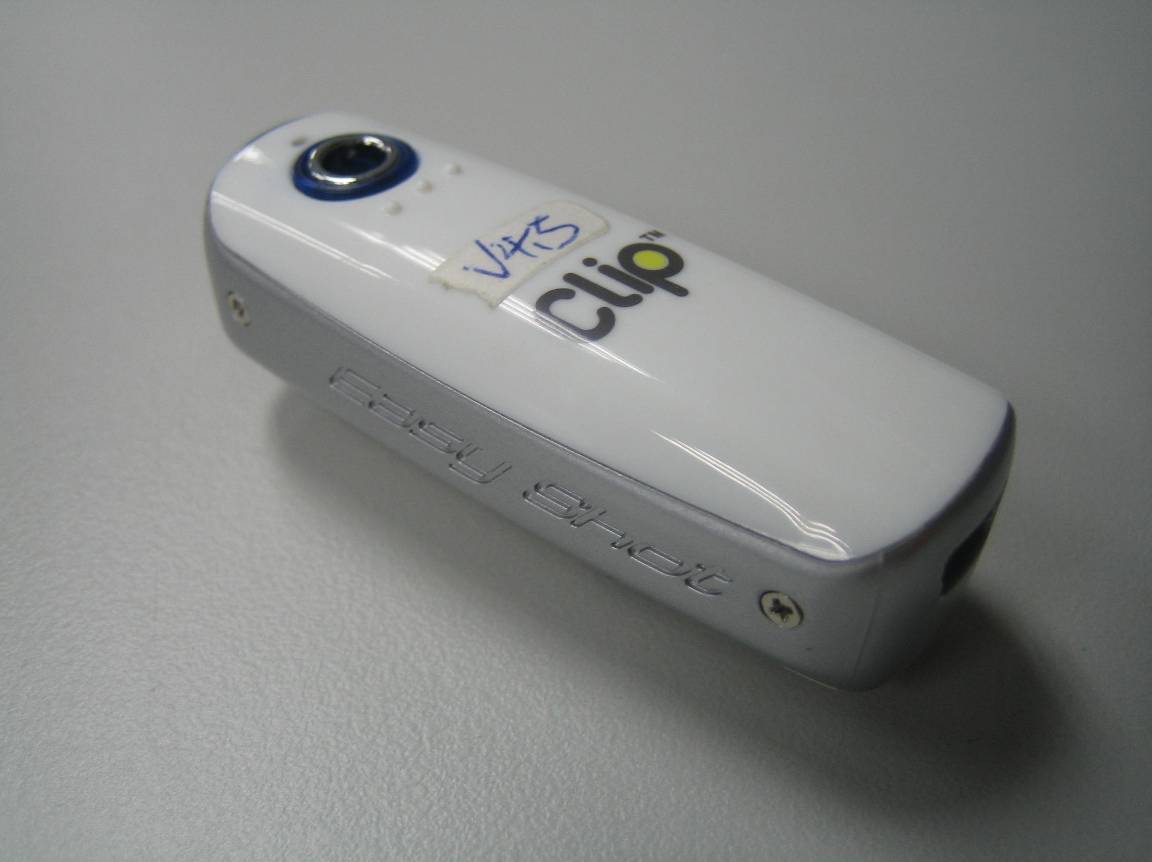
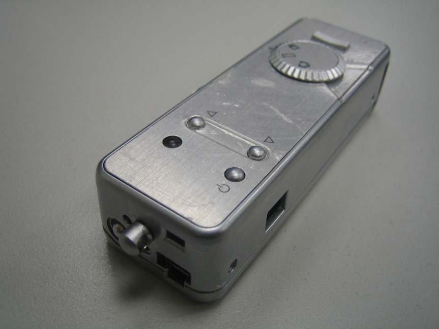
FCC Test Report E4128102401KYS1 Type / Model Name: 60651 Product Description: DIGITAL SPY CAMERA Applicant: GRANDTECH INDUSTRIAL LTD. FCC ID: WMD60651 FCC ID:WMD60651 File No. E4128102401KYS1, page 2 of 17 emitel (Shenzhen) Limited, Building 2, 171 Meihua Road, Futian District, Shenzhen, P.R.China 518049 F10_25_Rev5_0 Freigabe: 15.03.2006 FCC -- T E S T R E P O R T Test Report No. : E4128102401KYS1 May 14, 2010 ______________________________________________________________________________________________ Date of issue This report supercedes our previous report, E4128102401KY, dated April 22, 2010 Type / Model Name : 60651 Product Description : DIGITAL SPY CAMERA Applicant GRANDTECH INDUSTRIAL LTD. Address FLAT A1-2, 11/F., BLK. A, YEE LIM INDUSTRIAL CENTRE, 2-28 KWAI LOK STREET, KWAI CHUNG, N.T., HONG KONG Buyer :MINOX GmbH Address : Walter-Zapp-Strabe 4, D-35578 Wetzlar, GERMANY Test Result according to the standards listed in clause 1 test standards: PASS The test report merely corresponds to the test sample. It is not permitted to copy extracts of these test results without the written permission of the test laboratory. FCC ID:WMD60651 File No. E4128102401KYS1, page 3 of 17 emitel (Shenzhen) Limited, Building 2, 171 Meihua Road, Futian District, Shenzhen, P.R.China 518049 F10_25_Rev5_0 Freigabe: 15.03.2006 Contents 1 TEST STANDARDS 4 2 SUMMARY 5 3 EQUIPMENT UNDER TEST 6 3.1 PHOTO DOCUMENTATION OF THE EUT 6 3.2 POWER SUPPLY SYSTEM UTILISED 7 3.3 SHORT DESCRIPTION OF THE EQUIPMENT UNDER TEST (EUT) 7 4 TEST ENVIRONMENT 8 4.1 ADDRESS OF THE TEST LABORATORY 8 4.2 ENVIRONMENTAL CONDITIONS 8 4.3 STATEMENT OF THE MEASUREMENT UNCERTAINTY 8 5 TEST CONDITIONS AND RESULTS 9 5.1 CONDUCTED DISTURBANCE 9 5.2 RADIATED DISTURBANCE (ELECTRIC FIELD) 13 6 USED TEST EQUIPMENT AND ACCESSORIES 17 FCC ID:WMD60651 File No. E4128102401KYS1, page 4 of 17 emitel (Shenzhen) Limited, Building 2, 171 Meihua Road, Futian District, Shenzhen, P.R.China 518049 F10_25_Rev5_0 Freigabe: 15.03.2006 1 TEST STANDARDS The tests were performed according to following standards: FCC Part 15 Subpart B:2007-9-20 Radio frequency devices-Unintentional Radiators ANSI C63.4:2003 Method of Measurement of Radio-Noise Emissions from Low- Voltage Electrical and Electronic Equipment in the Range of 9 kHz to 40 GHz FCC ID:WMD60651 File No. E4128102401KYS1, page 5 of 17 emitel (Shenzhen) Limited, Building 2, 171 Meihua Road, Futian District, Shenzhen, P.R.China 518049 F10_25_Rev5_0 Freigabe: 15.03.2006 2 SUMMARY GENERAL REMARKS: None FINAL ASSESSMENT: The equipment under fulfils the FCC requirements cited in test standard listed in section 1. Date of receipt of test sample : October 29, 2009 Testing commenced on : October 29, 2009 Testing concluded on : April 29, 2010 Reviewed by: Prepared by: Wilson Loke Senior Manager Kidd Yang Engineer FCC ID:WMD60651 File No. E4128102401KYS1, page 6 of 17 emitel (Shenzhen) Limited, Building 2, 171 Meihua Road, Futian District, Shenzhen, P.R.China 518049 F10_25_Rev5_0 Freigabe: 15.03.2006 3 EQUIPMENT UNDER TEST 3.1 Photo documentation of the EuT Front View Back View FCC ID:WMD60651 File No. E4128102401KYS1, page 7 of 17 emitel (Shenzhen) Limited, Building 2, 171 Meihua Road, Futian District, Shenzhen, P.R.China 518049 F10_25_Rev5_0 Freigabe: 15.03.2006 3.2 Power supply system utilised Power supply voltage: DC 3.7V(250mAh lithium polymer battery pack) 3.3 Short description of the Equipment under Test (EuT) The EuT is a digital camera powered by a DC 3.7V 250mAh lithium polymer battery and recharged thru the USB port. It is used for digital photo taking and can download the photo to the PC thru the USB port. Number of tested samples: One Serial number: Not Labelled Dimensions: L: 9.0cm W: 3.0cm H: 2.5cm EuT operation mode: The equipment under test was operated during the measurement under the following conditions: - Operation mode 1: Download mode - Operation mode 2: Photo mode - EuT configuration: The following interface cables and peripheral devices were connected during the measurements: Interface cables: Interface cable Length Type Line Line termination [m] shielded unshielde d Serial Cable connect to PC 3.0 Serial port Cable Switch Simulator Power Cable of PC 2.0 3 wires LISN Parallel Cable connect to PC 3.0 Parallel port cable Switch Simulator USB Cable connect to EuT and PC 0.6 USB cable PC Peripheral devices: Kind of equipment Model and/or Manufacturer PC DELL Switch Simulator Schaffner FCC ID:WMD60651 File No. E4128102401KYS1, page 8 of 17 emitel (Shenzhen) Limited, Building 2, 171 Meihua Road, Futian District, Shenzhen, P.R.China 518049 F10_25_Rev5_0 Freigabe: 15.03.2006 4 TEST ENVIRONMENT 4.1 Address of the test laboratory emitel (Shenzhen) Limited Building 2, 171 Meihua Road, Futian District, Shenzhen, 518049 China FCC Registration No.: 746887 4.2 Environmental conditions During the measurement the environmental conditions were within the listed ranges: Temperature: 15-35 ° C Humidity: 30-60 % Atmospheric pressure: 86-106 kPa 4.3 Statement of the measurement uncertainty The data and results referenced in this document are true and accurate. The reader is cautioned that there may be errors within the calibration limits of the equipment and facilities. The measurement uncertainty was calculated for all measurements listed in this test report acc. to CISPR 16-4-2 /11.2003 „Uncertainties, statistics and limit modelling – Uncertainty in EMC measurements“ and is documented in the quality system acc. to ISO 17025. Furthermore, component and process variability of devices similar to that tested may result in additional deviation. The manufacturer has the sole responsibility of continued compliance of the device. FCC ID:WMD60651 File No. E4128102401KYS1, page 9 of 17 emitel (Shenzhen) Limited, Building 2, 171 Meihua Road, Futian District, Shenzhen, P.R.China 518049 F10_25_Rev5_0 Freigabe: 15.03.2006 5 TEST CONDITIONS AND RESULTS 5.1 Conducted disturbance For test instruments and accessories used see sect…
Text truncated - open the document above for the full version.
FCC ID: WMD60651 FCC ID: WMD60651
Building 2, 171 Meihua Road Futian District · Shenzhen · China
| # | Rule Parts | Frequency Range | Power Output |
|---|---|---|---|
| 1 | 15B | - | - |

Digital Video Camera
Equipment Class
JBP - Part 15 Class B Computing Device Peripheral