WPEPSASII-01Wireless reader(
Emerson Digital Cold Chain, Inc.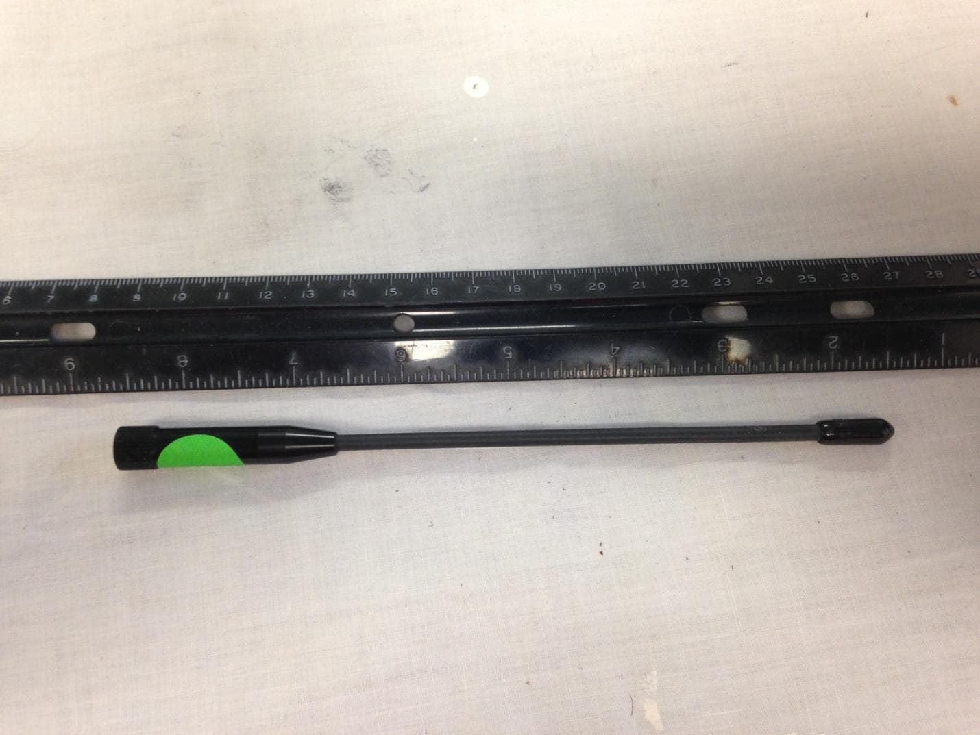
Click to zoom
Application Details
- Equipment Class
- DTS - Digital Transmission System
- Date of Grant
- Sep 30, 2014
- Application Purpose
- Original Equipment
- Date of Application
- Sep 30, 2014
- Equipment Note
- Wireless reader(
- Frequency Range
- 902.75000000 - 927.50000000
- Country
- United States
Documents & Files
Document Text
Text extracted from the exhibit documents filed with the FCC. Open a document above to read the original.
Users Manual
AutoSense II Quick Start Guide Configuration of Hardware 1. All hardware configurations will be accomplished for both Node and Gateway Units only by PakSense. CGTX boards will be installed only by qualified PakSense technicians. Installation and Operation of Hardware 1. Node and Gateway Units are to be installed in final use location by qualified technicians. 2. To begin operation of the installed unit, insert power cord into the hardware. 3. Plug in power supply into power outlet. Contact PakSense Customer Service: Email: [email protected] Toll free: (877) 832-0720 Video and Additional Resources:www.paksense.com Regulatory Information FCCpprovals Note: This equipment has been tested and found to comply with the limits for a Class B digital device, pursuant to part 15 of the FCC Rules. These limits are designed to provide reasonable protection against harmful interference in a residential installation. This equipment generates, uses and can radiate radio frequency energy and, if not installed and used in accordance with the instructions, may cause harmful interference to radio communications. However, there is no guarantee that interference will not occur in a particular installation. If this equipment does cause harmful interference to radio or television reception, which can be determined by turning the equipment off and on, the user is encouraged to try to correct the interference by one or more of the following measures: —Reorient or relocate the receiving antenna. —Increase the separation between the equipment and receiver. —Connect the equipment into an outlet on a circuit different from that to which the receiver is connected. —Consult the dealer or an experienced radio/TV technician for help. This device complies with Part 15 of the FCC Rules. Operation is subject to the following two conditions: (1) This device may not cause harmful interference, and (2) this device must accept any interference received, including interference that may cause undesired operation. This radio transmitter has been approved to operate with the antenna types listed below with the maximum permissible gain and required antenna impedance for each antenna type indicated. Antenna types not included in this list, having a gain greater than the maximum gain indicated for that type, are strictly prohibited for use with this device. Omni Directional Dipole, gain of 2.0 dB or Less Lithium Warning: Changes not expressly authorized by the manufacturer could void the user’s authority to operate this equipment. Industry Canada This device complies with Industry Canada licence-exempt RSS standard(s). Operation is subject to the following two conditions: (1) this device may not cause interference, and (2) this device must accept any interference, including interference that may cause undesired operation of the device. Le présent appareil est conforme aux CNR d'Industrie Canada applicables aux appareils radio exempts de licence. L'exploitation est autorisée aux deux conditions suivantes : (1) l'appareil ne doit pas produire de brouillage, et (2) l'utilisateur de l'appareil doit accepter tout brouillage radioélectrique subi, même si le brouillage est susceptible d'en compromettre le fonctionnement Under Industry Canada regulations, this radio transmitter may only operate using an antenna of a type and maximum (or lesser) gain approved for the transmitter by Industry Canada. To reduce potential radio interference to other users, the antenna type and its gain should be so chosen that the equivalent isotropically radiated power (e.i.r.p.) is not more than that necessary for successful communication. Conformément à la réglementation d'Industrie Canada, le présent émetteur radio peut fonctionner avec une antenne d'un type et d'un gain maximal (ou inférieur) approuvé pour l'émetteur par Industrie Canada. Dans le but de réduire les risques de brouillage radioélectrique à l'intention des autres utilisateurs, il faut choisir le type d'antenne et son gain de sorte que la puissance isotrope rayonnée équivalente (p.i.r.e.) ne dépasse pas l'intensité nécessaire à l'établissement d'une communication satisfaisante. This radio transmitter has been approved by Industry Canada to operate with the antenna types listed below with the maximum permissible gain and required antenna impedance for each antenna type indicated. Antenna types not included in this list, having a gain greater than the maximum gain indicated for that type, are strictly prohibited for use with this device. Omni Directional Dipole Gain of 2.0 dB or Less Le présent émetteur radio (identify the device by certification number, or model number if Category II) a été approuvé par Industrie Canada pour fonctionner avec les types d'antenne énumérés ci-dessous et ayant un gain admissible maximal et l'impédance requise pour chaque type d'antenne. Les types d'antenne non inclus dans cette liste, ou dont le gain est supérieur au gain maximal indiqué, sont strictement interdits pour l'exploitation de l'émetteur.
Cover Letter(s)
Request for Confidentiality Date: ___September 8, 2014 _____ Subject: Confidentiality Request for: ___FCC ID: WPEPSASII-01 IC: 8031A-PSASII01_ Pursuant to FCC 47 CRF 0.457(d) and 0.459 and IC RSP-100, Section 10, the applicant requests that a part of the subject FCC application be held confidential. Type of Confidentiality Requested Exhibit Short Term Permanent Block Diagrams Short Term External Photos Short Term Permanent Internal Photos Short Term Permanent Operation Description/Theory of Operation Short Term Permanent Parts List & Placement/BOM Short Term Permanent Tune-Up Procedure Short Term Permanent Schematics Short Term Test Setup Photos Short Term Permanent* User’s Manual Paksense has spent substantial effort in developing this product and it is one of the first of its kind in industry. Having the subject information easily available to "competition" would negate the advantage they have achieved by developing this product. Not protecting the details of the design will result in financial hardship. Permanent Confidentiality: The applicant requests the exhibits listed above as permanently confidential be permanently withheld from public review due to materials that contain trade secrets and proprietary information not customarily released to the public. NOTE for Industry Canada Applications: The applicant understands that until such time that IC distinguishes between Short Term and Permanent Confidentiality, either type of marked exhibit above will simply be marked Confidential when submitted to IC. Sincerely, By: __________________________ ___Sandi McEnery__- Agent (Signature/Title 1 ) (Print name)
External Photos
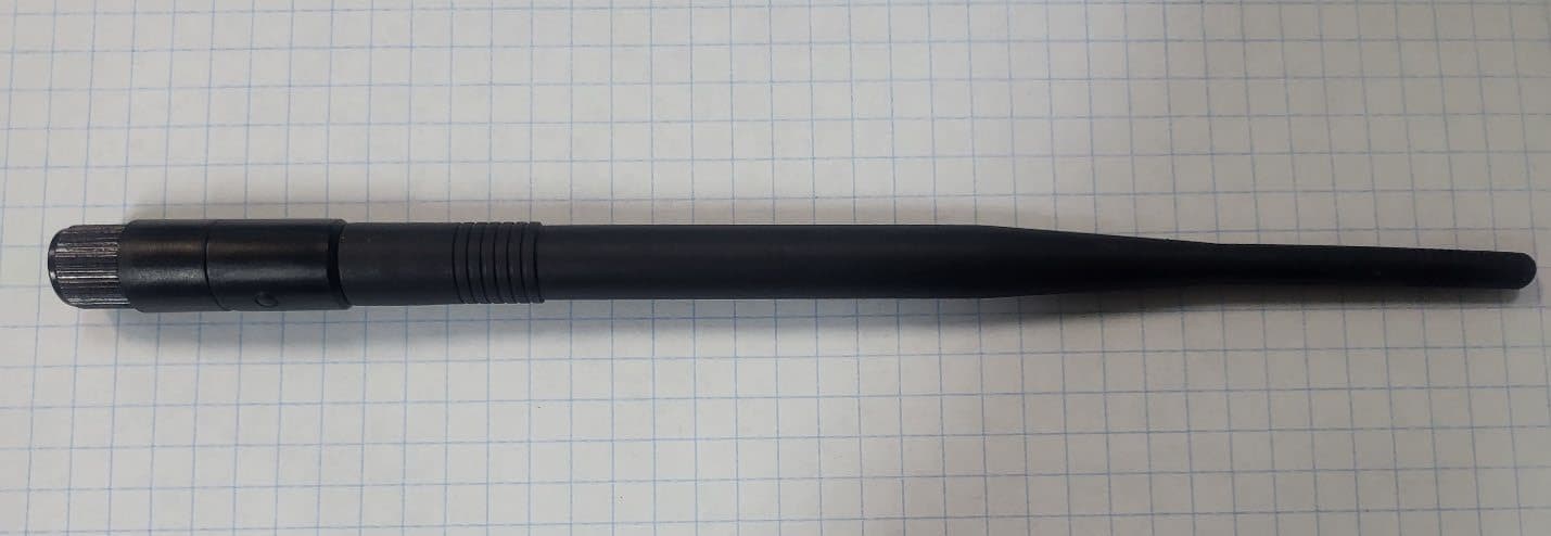
US Tech FCC Part 15.247/ RSS 210 Test Report: 14-0123 Date: September 8, 2014 Model(s): PSASII-01 FCC ID: WPEPSASII-01 IC: 8031A-PSASII01 Customer: Paksense ANTENNA PHOTOGRAPHS Figure 1. Antenna for Paksense Radio MFG: Nearson Type: Omni Directional Dipole antenna Gain: 2.0 dBi Connector: Reverse sex SMA connector US Tech FCC Part 15.247/ RSS 210 Test Report: 14-0123 Date: September 8, 2014 Model(s): PSASII-01 FCC ID: WPEPSASII-01 IC: 8031A-PSASII01 Customer: Paksense Figure 2. Antenna on EUT
External Photos
US Tech FCC Part 15.247/ RSS 210 Test Report: 14-0123 Date: September 8, 2014 Model(s): PSASII-01 FCC ID WPEPSASII-01 IC: 8031A-PSASII01 Customer: Paksense EXTERNAL PHOTOGRAPHS Photo 1 – Top of EUT US Tech FCC Part 15.247/ RSS 210 Test Report: 14-0123 Date: September 8, 2014 Model(s): PSASII-01 FCC ID WPEPSASII-01 IC: 8031A-PSASII01 Customer: Paksense Photo 2 – Back of EUT US Tech FCC Part 15.247/ RSS 210 Test Report: 14-0123 Date: September 8, 2014 Model(s): PSASII-01 FCC ID WPEPSASII-01 IC: 8031A-PSASII01 Customer: Paksense Photo 3 – Back of EUT, Close Up US Tech FCC Part 15.247/ RSS 210 Test Report: 14-0123 Date: September 8, 2014 Model(s): PSASII-01 FCC ID WPEPSASII-01 IC: 8031A-PSASII01 Customer: Paksense Photo 4 – Left Side of EUT US Tech FCC Part 15.247/ RSS 210 Test Report: 14-0123 Date: September 8, 2014 Model(s): PSASII-01 FCC ID WPEPSASII-01 IC: 8031A-PSASII01 Customer: Paksense Photo 5 – Top of EUT US Tech FCC Part 15.247/ RSS 210 Test Report: 14-0123 Date: September 8, 2014 Model(s): PSASII-01 FCC ID WPEPSASII-01 IC: 8031A-PSASII01 Customer: Paksense Photo 6 – Top of EUT, Close Up US Tech FCC Part 15.247/ RSS 210 Test Report: 14-0123 Date: September 8, 2014 Model(s): PSASII-01 FCC ID WPEPSASII-01 IC: 8031A-PSASII01 Customer: Paksense Photo 7 – Right Side of EUT US Tech FCC Part 15.247/ RSS 210 Test Report: 14-0123 Date: September 8, 2014 Model(s): PSASII-01 FCC ID WPEPSASII-01 IC: 8031A-PSASII01 Customer: Paksense Photo 8 – Bottom of EUT US Tech FCC Part 15.247/ RSS 210 Test Report: 14-0123 Date: September 8, 2014 Model(s): PSASII-01 FCC ID WPEPSASII-01 IC: 8031A-PSASII01 Customer: Paksense Photo 9 – Bottom of EUT, Close Up
ID Label/Location Info
US Tech FCC Part 15.247/ RSS 210 Test Report: 14-0123 Date: September 8, 2014 Model(s): PSASII-01 FCC ID WPEPSASII-01 IC: 8031A-PSASII01 Customer: Paksense SAMPLE LABEL (location is shown on following page) Label will go on Back of product as shown. Actual size is is 7/8 inches by 1 3/8 inches.
Internal Photos
US Tech FCC Part 15.247/ RSS 210 Test Report: 14-0123 Date: September 8, 2014 Model(s): PSASII-01 FCC ID: WPEPSASII-01 IC: 8031A-PSASII01 Customer: Paksense INTERNAL PHOTOGRAPHS Photo 1 – Top of EUT with External B Plates removed US Tech FCC Part 15.247/ RSS 210 Test Report: 14-0123 Date: September 8, 2014 Model(s): PSASII-01 FCC ID: WPEPSASII-01 IC: 8031A-PSASII01 Customer: Paksense Photo 2 – Bottom of EUT with External Plates Removed US Tech FCC Part 15.247/ RSS 210 Test Report: 14-0123 Date: September 8, 2014 Model(s): PSASII-01 FCC ID: WPEPSASII-01 IC: 8031A-PSASII01 Customer: Paksense Photo 3 – Inside of External Case US Tech FCC Part 15.247/ RSS 210 Test Report: 14-0123 Date: September 8, 2014 Model(s): PSASII-01 FCC ID: WPEPSASII-01 IC: 8031A-PSASII01 Customer: Paksense Photo 4 – Top of Circuit Board # 1 with Circuit Board #2 Attached US Tech FCC Part 15.247/ RSS 210 Test Report: 14-0123 Date: September 8, 2014 Model(s): PSASII-01 FCC ID: WPEPSASII-01 IC: 8031A-PSASII01 Customer: Paksense Photo 5 – Top of Circuit Board #1 with Circuit Board #2 Removed US Tech FCC Part 15.247/ RSS 210 Test Report: 14-0123 Date: September 8, 2014 Model(s): PSASII-01 FCC ID: WPEPSASII-01 IC: 8031A-PSASII01 Customer: Paksense Photo 6 – Bottom of Circuit Board #1 with Circuit Board #3 and #4 Attached Note: Paksense radio circled above US Tech FCC Part 15.247/ RSS 210 Test Report: 14-0123 Date: September 8, 2014 Model(s): PSASII-01 FCC ID: WPEPSASII-01 IC: 8031A-PSASII01 Customer: Paksense Photo 7 – Bottom of Circuit Board #1, no other Circuit Boards Attached US Tech FCC Part 15.247/ RSS 210 Test Report: 14-0123 Date: September 8, 2014 Model(s): PSASII-01 FCC ID: WPEPSASII-01 IC: 8031A-PSASII01 Customer: Paksense Photo 8 – Bottom of Circuit Board #2 (cellular module) US Tech FCC Part 15.247/ RSS 210 Test Report: 14-0123 Date: September 8, 2014 Model(s): PSASII-01 FCC ID: WPEPSASII-01 IC: 8031A-PSASII01 Customer: Paksense Photo 9 – Top of Circuit Board # 2 US Tech FCC Part 15.247/ RSS 210 Test Report: 14-0123 Date: September 8, 2014 Model(s): PSASII-01 FCC ID: WPEPSASII-01 IC: 8031A-PSASII01 Customer: Paksense Photo 10 – Top of Circuit Board #3 (WiFi module) US Tech FCC Part 15.247/ RSS 210 Test Report: 14-0123 Date: September 8, 2014 Model(s): PSASII-01 FCC ID: WPEPSASII-01 IC: 8031A-PSASII01 Customer: Paksense Photo 11 – Bottom of Circuit Board #3 US Tech FCC Part 15.247/ RSS 210 Test Report: 14-0123 Date: September 8, 2014 Model(s): PSASII-01 FCC ID: WPEPSASII-01 IC: 8031A-PSASII01 Customer: Paksense Photo 12 – Top of Circuit Board #4, (Paksense Radio) US Tech FCC Part 15.247/ RSS 210 Test Report: 14-0123 Date: September 8, 2014 Model(s): PSASII-01 FCC ID: WPEPSASII-01 IC: 8031A-PSASII01 Customer: Paksense Photo 13 –Top of Circuit Board #4, Close up of Radio US Tech FCC Part 15.247/ RSS 210 Test Report: 14-0123 Date: September 8, 2014 Model(s): PSASII-01 FCC ID: WPEPSASII-01 IC: 8031A-PSASII01 Customer: Paksense Photo 14 – Bottom of Circuit Board #4
RF Exposure Info
US Tech Test Report: FCC Part 15.247/ RSS 210 Report Number: 14-0123 Customer: Paksense FCC ID: WPEPSASII-01 IC: 8031A-PSASII01 Issue Date: September 8, 2014 Model: PSASII-01 Page 1 of 1 Maximum Public Exposure to RF (MPE) The maximum exposure level to the public from the RF power of the EUT shall not exceed a power density, S, of 1 mW/cm 2 at a distance, d, of 20 cm from the EUT. Therefore, for: Measured maximum output power: + 3.5 dBm Highest Gain Antenna (Dipole antenna) = 2.0 dBi Peak Power (Watts) = 0.002 (Manufacture’s claimed highest output power) Gain of Transmit Antenna = 2.0 dB i = 1.585, numeric (from Table 4 of Test Report) d = Distance = 20 cm = 0.2 m S = (PG/ 4d 2 ) = EIRP/4A = (0.002*1.585)/4*π*0.2*0.2 = 0.00317/0.5027 = 6.3065 W/m 2 = (W/m 2 ) (1m 2 /W) (0.1 mW/cm 2 ) = 0.63065 mW/cm 2 which is < less than 1.0 mW/cm 2
Test Report
CROSS REFERENCE FCC/IC RSS-210 FOR Paksense, Inc. FCC ID: WPEPSASII-01 IC: 8031A-PSAS1101 TEST IC RSS-210 ISSUE 8 IC RSS Gen ISSUE 3 FCC Transmit Antenna Requirement A8.4(1) 15.203 Fundamental Peak Power A8.1(a-e) A8.4(1) 15.247 Antenna Conducted Spurious Emissions RSS Gen 6.2 N/A Field Strength of Spurious Emissions Average Radiated Peak Radiated A2.9 RSS Gen Section 6.0 15.247 & 15.209 Frequency Tolerance N/A N/A 20 dB Bandwidth A8.1 15.247 Conducted ICES-003 15.207(a) & 15.107(a) Digital Device Radiated ICES-003 15.109(a) Modular Approval RSS-Gen 3.2 15.212 Antenna Requirement RSS-Gen 7.1.2 15.203 Frequency Range of Radiated measurement RSS-Gen 4.10 15.33
Test Report
Page 1 of 56 Application For Part 2, Subpart J, Paragraph 2.907 Equipment Authorization of Certification for an Intentional Radiator per Part 15, Subpart C, paragraphs 15.207, 15.209 and 15.247 And Part 2, Subpart J, Section 2.902, Verification Per Part 15, Subpart B, for Unintentional Radiators, section 15.101, 15.107 and 15.109 For the PakSense Model: PSASII-01 FCC ID: WPEPSASII-01 IC ID:8031A-PSASII01 UST Project: 14-0123 Issue Date: September 10, 2014 Total Pages in This Report: 56 3505 Francis Circle Alpharetta, GA 30004 PH: 770-740-0717 Fax: 770-740-1508 www.ustech-lab.com Page 2 of 56 I certify that I am authorized to sign for the Test Agency and that all of the statements in this report and in the Exhibits attached hereto are true and correct to the best of my knowledge and belief: US TECH (Agent Responsible For Test): By: Alan Ghasiani Name: Title: Compliance Engineer – President Date September 10, 2014 This report shall not be reproduced except in full. This report may be copied in part only with the prior written approval of US Tech. The results contained in this report are subject to the adequacy and representative character of the sample provided. This report must not be used to claim product certification, approval, or endorsement by NVLAP, NIST or any agency of the Federal Government. 3505 Francis Circle Alpharetta, GA 30004 PH: 770-740-0717 Fax: 770-740-1508 www.ustech-lab.com US Tech Test Report: FCC Part 15 Certification/ RSS 210 FCC ID: WPEPSASII-01 IC ID: 8031A-PSASII01 Test Report Number: 14-0123 Issue Date: September 10, 2014 Customer: Paksense Model: PSASII-01 Page 3 of 56 MEASUREMENT TECHNICAL REPORT COMPANY NAME: PakSense MODEL: PSASII-01 FCC ID: WPEPSASII-01 IC ID: 8031A-PSASII01 DATE: September 10, 2014 This report concerns (check one): Original grant X Class II change Equipment type: 902-928 MHz Transmitter Module Deferred grant requested per 47 CFR 0.457(d)(1)(ii)? yes_____ No X If yes, defer until: ______N/A___________ date agrees to notify the Commission by N/A date of the intended date of announcement of the product so that the grant can be issued on that date. Report prepared by: US Tech 3505 Francis Circle Alpharetta, GA 30004 Phone Number: (770) 740-0717 Fax Number: (770) 740-1508 US Tech Test Report: FCC Part 15 Certification/ RSS 210 FCC ID: WPEPSASII-01 IC ID: 8031A-PSASII01 Test Report Number: 14-0123 Issue Date: September 10, 2014 Customer: Paksense Model: PSASII-01 Page 4 of 56 Table of Contents Paragraph Title Page 1 General Information .......................................................................................... 7 1.1 Purpose of this Report .................................................................................. 7 1.2 Characterization of Test Sample .................................................................. 7 1.3 Product Description ...................................................................................... 7 1.4 Configuration of Tested System .................................................................... 8 1.5 Test Facility ................................................................................................... 8 2 Tests and Measurements ............................................................................... 10 2.1 Test Equipment ........................................................................................... 10 2.2 Modifications to EUT Hardware .................................................................. 11 2.3 Number of Measurements for Intentional Radiators (15.31(m)) .................. 11 2.4 Frequency Range of Radiated Measurements (Part 15.33) ...................... 11 2.4.1 Intentional Radiator .................................................................................. 11 2.4.2 Unintentional Radiator ............................................................................. 12 2.5 Measurement Detector Function and Bandwidth (CFR 15.35) ................... 12 2.5.1 Detector Function and Associated Bandwidth ......................................... 12 2.5.2 Corresponding Peak and Average Requirements .................................... 12 2.5.3 Pulsed Transmitter Averaging .................................................................. 12 2.6 EUT Antenna Requirements (CFR 15.203) ................................................ 13 2.7 Restricted Bands of Operation (Part 15.205) .............................................. 14 2.8 Transmitter Duty Cycle (CFR 35 (c)) .......................................................... 14 2.9 Intentional Radiator, Power Lines Conducted Emissions (CFR 15.207) ..... 17 2.10 Intentional Radiator, Radiated Emissions (CFR 15.209, 15.247(d)) (IC RSS 210, A2.9 (a)) ....................................................................................................... 17 2.11 Intentional Radiator, Radiated Emissions (CFR 15.209, 15.247(d)) (IC RSS 210, A2.9 (a)) ............................................................................................... 27 2.12 Band Edge Measurements – (CFR 15.247 (d)) ....................................... 30 2.13 Six (6) dB Bandwidth per CFR 15.247(a)(2), ........................................... 35 2.14 99% Occupied Bandwidth (IC RSS 210, A8.1) ........................................ 39 2.15 Maximum Peak Conducted Output Power (CFR 15.247 (b) (3)) ............. 43 2.16 Power Spectral Density (CFR 15.247(e)) (IC RSS 210 A8.5) ................. 47 2.17 Unintentional Radiator, Powerline Emissions (CFR 15.107) ....................... 51 2.18 Unintentional Radiator, Radiated Emissions (CFR 15.109) ......................... 53 2.19 Measurement Uncertainty ............................................................................ 56 2.19.1 Conducted Emissions Measurement Uncertainty .................................. 56 2.19.2 Radiated Emissions Measurement Uncertainty ..................................... 56 US Tech Test Report: FCC Part 15 Certification/ RSS 210 FCC ID: W…
Text truncated - open the document above for the full version.
Test Setup Photos
US Tech FCC Part 15.247/ RSS 210 Test Report: 14-0123 Date: September 8, 2014 Model(s): PSASII-01 FCC ID: WPEPSASII-01 IC: 8031A-PSASII01 Customer: Paksense TEST CONFIGURATION PHOTOGRAPHS Photo 1- Radiated Emissions Test Setup, Front, with RF Label US Tech FCC Part 15.247/ RSS 210 Test Report: 14-0123 Date: September 8, 2014 Model(s): PSASII-01 FCC ID: WPEPSASII-01 IC: 8031A-PSASII01 Customer: Paksense Photo 2- Radiated Emissions Test Setup, Front, without RF Label US Tech FCC Part 15.247/ RSS 210 Test Report: 14-0123 Date: September 8, 2014 Model(s): PSASII-01 FCC ID: WPEPSASII-01 IC: 8031A-PSASII01 Customer: Paksense Photo 3- Radiated Emissions Test Setup, .15 MHz to 300 MHz, with RF Label, Back US Tech FCC Part 15.247/ RSS 210 Test Report: 14-0123 Date: September 8, 2014 Model(s): PSASII-01 FCC ID: WPEPSASII-01 IC: 8031A-PSASII01 Customer: Paksense Photo 4- Radiated Emissions Test Setup, 30 MHz to 200 MHz, Back US Tech FCC Part 15.247/ RSS 210 Test Report: 14-0123 Date: September 8, 2014 Model(s): PSASII-01 FCC ID: WPEPSASII-01 IC: 8031A-PSASII01 Customer: Paksense Photo 5- Radiated Emissions Test Setup, 200 MHz to 1GHz, with RF Label, Back US Tech FCC Part 15.247/ RSS 210 Test Report: 14-0123 Date: September 8, 2014 Model(s): PSASII-01 FCC ID: WPEPSASII-01 IC: 8031A-PSASII01 Customer: Paksense Photo 6- Fundamental Emissions Test Setup, without RF Label, Back US Tech FCC Part 15.247/ RSS 210 Test Report: 14-0123 Date: September 8, 2014 Model(s): PSASII-01 FCC ID: WPEPSASII-01 IC: 8031A-PSASII01 Customer: Paksense Photo 7- Radiated Emission Test Setup, above 1 GHz, with RF Label, Back US Tech FCC Part 15.247/ RSS 210 Test Report: 14-0123 Date: September 8, 2014 Model(s): PSASII-01 FCC ID: WPEPSASII-01 IC: 8031A-PSASII01 Customer: Paksense Photo- 8 Harmonics Measurement, without RF Label, Back US Tech FCC Part 15.247/ RSS 210 Test Report: 14-0123 Date: September 8, 2014 Model(s): PSASII-01 FCC ID: WPEPSASII-01 IC: 8031A-PSASII01 Customer: Paksense Photo 9- Conducted Emissions Test Setup, with RF Label
Contact Information
Applicant
Amy Childress(VP General Manager)
Test Firm
US TechGeorge Yang
Technical Specifications
| # | Rule Parts | Frequency Range | Power Output |
|---|---|---|---|
| 1 | 15C | 902.75 MHz - 927.5 MHz | 2.24 mW |
Other Applications from Emerson Digital Cold Chain, Inc.
WPEPSASII-04
Aug 01, 2024900 MHz ISM transceiver module
Equipment Class
DTS - Digital Transmission System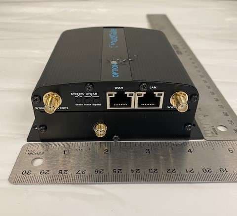
WPEPSASII-03
Mar 03, 2020Transceiver base station device
Equipment Class
DTS - Digital Transmission System