WQE5237001Subscriber unit transceiver
Siemens Canada Limited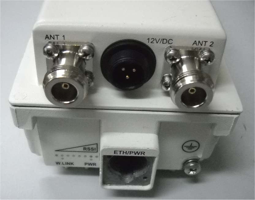
Click to zoom
Application Details
- Equipment Class
- TNB - Licensed Non-Broadcast Station Transmitter
- Date of Grant
- Aug 03, 2011
- Application Purpose
- Original Equipment
- Date of Application
- Jun 22, 2011
- Equipment Note
- Subscriber unit transceiver
- Frequency Range
- 3655.00000000 - 3695.00000000
- Company
- Siemens Canada Limited
- Country
- Canada
Documents & Files
Document Text
Text extracted from the exhibit documents filed with the FCC. Open a document above to read the original.
Users Manual
User’s Manual & Installation Guide for: WiN52XX/WiN51XX Series Outdoor CPE ALL RIGHTS RESERVED Dissemination or reproduction of this document, or evaluation and communication of its contents, is not authorized except where expressly permitted. Violations are liable for damages. All rights reserved, particularly for the purposes of patent application or trademark registration. This document contains proprietary information, which is protected by copyright. All rights are reserved. No part of this document may be photocopied, reproduced or translated to another language without prior written consent of RuggedCom Inc. Disclaimer Of Liability We have checked the contents of this manual against the hardware and software described. However, deviations from the description cannot be completely ruled out. RuggedCom shall not be liable for any errors or omissions contained herein or for consequential damages in connection with the furnishing, performance, or use of this material. The information given in this document is reviewed regularly and any necessary corrections will be included in subsequent editions. We appreciate any suggested improvements. We reserve the right to make technical improvements without notice. Registered Trademarks RuggedMAX-BST™, RuggedServer™, RuggedWireless™, RuggedCom Discovery Protocol™ (RCDP™), RuggedExplorer™, Enhanced Rapid Scanning Tree Protocol™ (eRSTP™), are trademarks of RuggedCom Inc. Rugged Operating System® (ROS®) and RuggedSwitch® are registered trademarks of RuggedCom Inc. Other designations in this manual might be trademarks whose use by third parties for their own purposes would infringe the rights of the owner. Warranty Five (5) years from date of purchase, return to factory. For warranty details, visit www.ruggedcom.com or contact your customer service representative. Contacting RuggedCom Corporate Headquarters US Headquarters Europe Headquarters RuggedCom Inc 30 Whitmore Road Woodbridge, Ontario Canada, L4L 7Z4 Tel: (905) 856-5288 Fax: (905) 856-1995 Toll-free: 1 (888) 264-0006 RuggedCom 1930 Harrison St., Suite 209 Hollywood, Florida USA, 33020 Tel: (954) 922-7938x103 Fax: (954) 922-7984 Toll-free: 1 (888) 264-0006 RuggedCom Unit 41, Aztec Centre, Aztec West, Almondsbury, Bristol United Kingdom BS32 4TD Tel: +44 1454 203 404 Fax: +44 1454 203 404 Toll-free: 1 (888) 264-0006 Email: [email protected] WiN5200 Table of Contents | 3 Table of Contents Introduction......................................................................................................... 6 1.1 About this Manual ................................................................................................................7 1.2 General Description ............................................................................................................7 1.2.1 Features .....................................................................................................................8 1.3 Package Components and Unpacking .............................................................................8 1.4 Safety Information ...............................................................................................................8 Product Description......................................................................................... 11 2.1 Introduction .........................................................................................................................12 2.2 IEEE 802.16e Mobile WiMAX Compliance ....................................................................13 2.3 Block Diagram ....................................................................................................................14 2.4 Features ..............................................................................................................................15 2.4.1 Mobile WiMAX Wave 2 MIMO Features .............................................................15 2.4.2 Security ....................................................................................................................17 2.4.3 Time Division Duplexing (TDD) ............................................................................20 2.4.4 Coding Rate ............................................................................................................20 2.4.5 Modulation ...............................................................................................................20 2.4.6 Convolution Coding Error Correction ..................................................................21 2.5 Deployment Models ..........................................................................................................21 2.5.1 PTP Deployment ....................................................................................................21 2.5.2 PMP Deployment ...................................................................................................21 2.5.3 Non Line-of-Sight ...................................................................................................21 2.5.4 Channelization ........................................................................................................21 2.6 Service Flows .....................................................................................................................22 2.6.1 Service Flow Classification ...................................................................................22 2.6.2 Dynamic Service Addition .....................................................................................22 2.6.3 Default Service Flows ............................................................................................23 WiN5200 Table of Contents | 4 2.6.4 Scheduling ...............................................................................................................23 2.7 Physical Description ........................................................................................................…
Text truncated - open the document above for the full version.
Cover Letter(s)
Page 1 of 1 June 23, 2011 Federal Communication Commission Office of Engineering and Technology USA Subject: Application for certification of the subscriber unit transceiver, FCC ID:WQE5237001 Dear Gentlemen, Please find attached our application for certification of the subscriber unit transceiver, FCC ID: WQE5237001, model names WiN5137-AC, WiN5237-DC, WiN5237 prepared in accordance with FCC Rules, parts 2 and 90, operating frequencies 3652.5-3697.5 MHz. The product testing and this application for certification were performed by Hermon Laboratories, which is listed by FCC (Registration Numbers 90623, 90624). The FCC Designation Number is US1003. Hermon Labs responsible person is Mr. Michael Nikishin, EMC and Radio group manager, tel: 011 972 4626 8440, fax:011 972 4628 8277, e-mail:[email protected]. We hope this application satisfies your requirements. Sincerely, Dudi Magen HW&RF Group Manager
Cover Letter(s)
Page 1 of 1 June 23, 2011 Federal Communication Commission Office of Engineering and Technology USA Subject: Request for confidentiality, FCC ID: WQE5237001 Dear Gentlemen, Pursuant to section 47 CFR 0.459 we hereby request non-disclosure and Long-Term Confidential treatment of the following materials submitted in support of FCC ID: WQE5237001 application for certification: 1) Schematic diagram 2) Parts list 3) Tune-up procedure. These exhibits contain trade secrets, proprietary and technical information which would customarily be guarded from competitors under 47 CFR section 0.457(d)(2). Disclosure or publication of any portion of this company confidential material could cause substantial competitive harm and provide unjustified benefits for competitors. Sincerely, Dudi Magen HW&RF Group Manager
External Photos
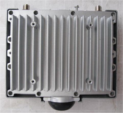
Ruggedcom Ltd. FCC ID:WQE5237001 External_photos_21650.doc Page 1 of 5 EXTERNAL PHOTOGRAPHS This document contains 4 photographs Ruggedcom Ltd. FCC ID:WQE5237001 External_photos_21650.doc Page 2 of 5 Photograph No.1 Subscriber unit WiN5137 front view Ruggedcom Ltd. FCC ID:WQE5237001 External_photos_21650.doc Page 3 of 5 Photograph No.2 Subscriber unit WiN5137 rear side view Ruggedcom Ltd. FCC ID:WQE5237001 External_photos_21650.doc Page 4 of 5 Photograph No.3 Subscriber unit WiN5137-AC side view Ruggedcom Ltd. FCC ID:WQE5237001 External_photos_21650.doc Page 5 of 5 Photograph No.4 Subscriber unit WiN5137-DC side view
ID Label/Location Info
FCC ID:WQE5237001 Ruggedcom Ltd. Page 1 of 1 Label location A subscriber unit shall bear the label with FCC ID:WQE5237001 on a front panel as shown in the photo below: Label with FCC ID:WQE5237001 will be placed here. Label
Internal Photos
Ruggedcom Ltd. FCC ID:WQE5237001 Page 1 of 10 INTERNAL PHOTOGRAPHS This document contains 9 photographs Ruggedcom Ltd. FCC ID:WQE5237001 Page 2 of 10 Photograph No.1 Subscriber unit WiN5137 internal view Ruggedcom Ltd. FCC ID:WQE5237001 Page 3 of 10 Photograph No.2 Subscriber unit power amplifier PCB front view Ruggedcom Ltd. FCC ID:WQE5237001 Page 4 of 10 Photograph No.3 Subscriber unit power amplifier PCB second side view Ruggedcom Ltd. FCC ID:WQE5237001 Page 5 of 10 Photograph No.4 Subscriber unit internal view with PA PCB removed Ruggedcom Ltd. FCC ID:WQE5237001 Page 6 of 10 Photograph No.5 Subscriber unit RF card front view Ruggedcom Ltd. FCC ID:WQE5237001 Page 7 of 10 Photograph No.6 Subscriber unit RF card second side view Ruggedcom Ltd. FCC ID:WQE5237001 Page 8 of 10 Photograph No.7 RF card front view with shield removed Ruggedcom Ltd. FCC ID:WQE5237001 Page 9 of 10 Photograph No.8 Subscriber unit main PCB front view Ruggedcom Ltd. FCC ID:WQE5237001 Page 10 of 10 Photograph No.9 Subscriber unit main PCB second side view
Operational Description
FCC ID:WQE5237001 Operational description The WiN51XX/WiN52XX ODU CPE is an IEEE 802.16‐2005 compliant wireless device for deployment of point‐to‐multipoint (PMP) and point‐to‐point (PTP) network architectures. The WiN51XX/WiN52XX ODU CPE is an outdoor device. The WiN51XX/WiN52XX ODU CPE is WiMAX Forum 802.16e Wave 2 (MIMO) certified subscribers. Each subscriber registers and establishes a bi‐directional data link with the base station sector controller. The base station is connected to the head‐end over IP Backhaul or via wireless channels. The outdoor CPEs are connected to the base station over wireless channels. The outdoor CPE is connected to the indoor residential gateway over Ethernet or coaxial networks. Frequency range: WiN5237, WiN5137‐AC, WiN5137‐DC: 3650 – 3700 MHz The CPE consists of the following modules: Base‐Band board – including the WiMAX 16e MIMO Base‐Band SoC (running the 16e MAC + PHY) plus the User Interface plus the analog front end that interface the RF module. Power Supply board– DC/DC power supply. Converts the 48VDC to the various voltages that are feeding the Digital and the RF modules RF board ‐ Single transmit dual receive module that modulate the analog WiMAX signal input from the Base‐Band modem to the high frequency RF output. Audio filter (Mobile Unit only) Chassis The WiN51XX/WiN52XX CPE uses time division duplexing (TDD) to transmit and receive on the same RF channel. This is a non‐contention based method for providing an efficient and predictable two‐way PTP or PMP cell deployment. All uplink and downlink transmission scheduling is managed by the base station. The modulation technique specifies how the data is coded within the OFDMA carriers. The base station supports QPSK, 16 QAM, and 64 QAM modulations. The RF Amplifier has Vcc=5.5V and DC current 0.6A.
Operational Description
MTI WIRELESS EDGE LTD. MT – 385002/CD REV-B SCALE: NONE DOC NO. RD42409100C SHEET 1 OF 4 Specification For MT – 385002/CD Dual Slant ± 45 deg Subscriber Antenna 3.3 – 3.8 GHz, 18 dBi THIS DOCUMENT AND THE INFORMATION CONTAINED IN IT ARE PROPRIETARY AND CONFIDENTIAL TO MTI. NO PERSON IS ALLOWED TO COPY REPRINT REPRODUCE OR PUBLISH ANY PART OF THIS DOCUMENT NOR DISCLOSE ITS CONTENTS TO OTHERS NOR MAKE ANY USE OF IT NOR ALLOW OR ASSIST OTHERS TO MAKE ANY USE OF IT, UNLESS BY THE PRIOR WRITTEN EXPRESS AUTHORIZATION OF MTI AND THEN ONLY TO THE EXTENT AUTHORIZED. (C) COPYRIGHT –MTI WIRELESS EDGE LTD. MTI WIRELESS EDGE LTD. SPECIFICATION FOR MT – 385002/CD Dual Slant ± 45 deg Antenna DOC NO. RD42409100C 3.3-3.8 GHz, 18 dBi SCALE: NONE CLASSIFICATION: NONE REV-B SHEET 2 OF 4 REVISION RECORD REV ECO DESCRIPTION APVD DATE 01 UPFATE GAIN YAEL H. 13.3.08 A CZ36 RELAESED YAEL H. 16.3.08 B 3116 CHANGE IP FROM 64 TO 65 YAEL H. 30.4.08 SHEET 43 44 45 46 47 48 49 50 51 52 53 54 55 56 REV SHEET 29 30 31 32 33 34 35 36 37 38 39 40 41 42 REV SHEET 15 16 17 18 19 20 21 22 23 24 25 26 27 28 REV SHEET 1 2 3 4 5 6 7 8 9 10 11 12 13 14 REV B B B B PRODUCT STATUS: PROPOSAL IN DEVELOPMENT PREPRODUCTION PRODUCTION CONTRACT NO ACTION NAME SIGN DATE PREP YAEL HARASH YAEL 29.1.08 CHKD DANIEL ZERAH D.Z 13.3.08 CHKD CHKD DSGN MICHAEL HAIKIN M.H 6.3.08 PROJ MOTI ROSTMY M.R 6.3.08 MFG QA MOTI MOTOVICH MOTI 10.308 MARK. DAVID ASHKENAZI D.A 13.3.08 MTI WIRELESS EDGE LTD. SPECIFICATION FOR MT – 385002/CD Dual Slant ± 45 deg Antenna DOC NO. RD42409100C 3.3-3.8 GHz, 18 dBi SCALE: NONE CLASSIFICATION: NONE REV-B SHEET 3 OF 4 SPECIFICATION Dual Slant ± 45 deg Antenna MTI PART NUMBER MT 385002/CD Regulatory Compliance ETSI EN 302 326-3 V1.1.2 ( 2006 -03 ) RoHS , CE 0682 ELECTRICAL. 1 Frequency Range 3.3 – 3.8 GHz Gain 17.5 dBi (min) @ 3.3 – 3.4GHz 18.0 dBi (min) @ 3.4 – 3.7GHz 17.5 dBi (min) @ 3.7 – 3.8GHz VSWR 2.0 : 1 (max) 3 dB Beamwidth 15° ± 2° Polarization Linear Dual Slant ± 45º Sidelobes Level ETSI EN 302 326-3 V1.1.2 DN3 Cross Polarization ETSI EN 302 326-3 V1.1.2 DN3@ 3.3 - 3.7 GHz DN2@ 3.7 - 3.8 GHz F/B Ratio ETSI EN 302 326-3 V1.1.2 DN3 - 30 dB (max) Port To Port Isolation 25 dB (min) @ 3.3 - 3.6 GHz 23 dB (min) @ 3.6 - 3.7 GHz 20 dB (min) @ 3.7 - 3.8 GHz Input Impedance 50 Ohms Input Power 6 Watts Lightning Protection DC Grounded MECHANICAL. 2 Antenna Dimensions (H x W x D) 305 x 305 x 15 mm (max) Weight 1.2 (kgs) (max) Connector 2 x MCX plug with 15 cm coaxial cable RG-316 Radome Plastic UV Resistant Base Plate Aluminum with chemical conversion coating Outline Drawing RD42443300C MTI WIRELESS EDGE LTD. SPECIFICATION FOR MT – 385002/CD Dual Slant ± 45 deg Antenna DOC NO. RD42409100C 3.3-3.8 GHz, 18 dBi SCALE: NONE CLASSIFICATION: NONE REV-B SHEET 4 OF 4 3 . ENVIRONMENTAL TEST STANDARD DURATION TEMPERTURE NOTES Low Temperature IEC 68-2-1 72 h -55°C - High Temperature IEC 68-2-2 72 h +71°C - Temp. Cycling IEC 68-2-14 1 h -45°C +70°C 3 Cycles Vibration IEC 60721-3-4 30 min/axis - Random 4M5 Shock Mechanical IEC 60721-3-4 - - 4M5 Humidity ETSI EN300-2-4 T4.1E 144 h - 95% Water Tightness IEC 529 - - IP65 Solar Radiation ASTM G53 1000 h - - Salt Spray IEC 68-2-11 Ka 500 h - - Ice And Snow - - - 25mm Radial Wind Speed Survival Operation - - - - - - 220 Km/h 160 Km/h Wind Load (Survival): Front Thrust Side Thrust - - - - - - 26.8 kg 1.3 kg
Operational Description
FCC ID:WQE5237001 CBP Questionnaire for RuggedCom CPE 2.1. Unrestricted Protocol Description Address the key requirements for operation using unrestricted contention based protocol. Please note that this requires recognizing other systems (both similar to yours and different from yours) that operate on a co-channel. Indicate the strategy for sharing the spectrum in terms of: (1) Does the system use spectrum sensing to determine if the other devices are transmitting and then find ways to share the bandwidth, or (2) Does the system have some other strategy? Answer: The FCC mentions the WiMAX technology as an example of restricted contention protocol: “34. Under the Commission’s rules, contention-based protocols can be broadly categorized as either “unrestricted” or “restricted.” ... Restricted contention protocols can prevent interference only with other devices incorporating the same protocol. WiMAX, with its scheduling protocol, currently stands as the main example of a restricted contention technology. In its present format, WiMAX technology effectively prevents interference among multiple transmitters on a single WiMAX system. Different WiMAX systems can be coordinated to avoid interfering with each other, thus providing each WiMAX device a “reasonable opportunity to operate.” (FCC 07-99). WiMAX Protocol Brief: WiMAX MAC protocol is a centralized protocol in which the base station controls access to the air interface. In the downlink, all decisions related to the allocation of bandwidth to various MSs are made by the BS, which does not require the involvement of the MS. As packets arrive for each terminal, the BS schedules them for the PHY resources, based on their QoS requirements. Once dedicated PHY resources have been allocated for the transmission of the MAC PDU, the BS indicates this allocation to the MS, using the specific MAC messages. In general, WiMAX terminal is a slave to the BS. In the uplink, the MS requests resources by using a contention bases protocol. WiMAX uses a truncated binary exponential back off algorithm for contention-resolution during polling of user terminals. When it needs to send a bandwidth request the MS first enters a contention resolution phase, if selecting a uniformly distributed random number between 0 and BACKOFF WINDOW. This random value indicates the number of transmission opportunities—allocated resources for multicast/broadcast poll—the MS will wait before sending its bandwidth request. BACKOFF WINDOW is the maximum number of transmission opportunities an MS can wait before sending the pending bandwidth request. If it does not receive a bandwidth allocation based on the UL MAP message within a time window specified by a timer, the MS assumes that its bandwidth request message was lost, owing to collision with another MS, in which case MS increases is back off window and repeats the process. If bandwidth is still not allocated after a maximum number of retries, the MAC PDU is discarded. FCC ID:WQE5237001 Spectrum Sensing In addition to the standard WiMAX CBP, the BS is equipped with interference level sensor which is able to sense the presence of other systems in the frequency operation. In WiMAX the BS and MS communicate in the master – slave mode, where BS is the master and MS is the slave. Thus, the signals transmitted by the MS are controlled by the BS. 2.2. Threshold detection to determine occupancy 2.2.1. Describe how your system determines if another system is using the spectrum. At what detection level – relative to 0 dBi receive antenna gain (busy channel threshold), does the device determine if another system is operating on the spectrum? Answer: In WiMAX CPE operation is controlled by the BS via the DL and UL maps passed from the BS to MS. The BS product is designed to listen to the environment signals by HW means and detect their power. Once the detected power is higher that a predefined threshold it is decided that there is another system operating in the same spectrum. The threshold is configurable and its default value is -90 dBm. 2.2.2. How long does the system observe to determine if the channel is busy – at the initial time and in between communications? Answer: The spectrum is observed in between communications in time periods in which the system is silent, which are the TTG and RTG gaps (the duration of each gap is about 50 microseconds). 2.2.3. What is the bandwidth being monitored versus bandwidth occupied for all modes of operation? Answer: The whole occupied bandwidth is being monitored. 2.2.4. How much variability is provided to the system operator to adjust busy channel detection threshold? Answer: The detection threshold is configurable by the operator. Its range is -90 to-45 dBm. 2.2.5. What is the operating system threshold (receive threshold) compared to the monitoring threshold (busy channel threshold)? Answer: The default monitoring threshold is approximately the same as the receive threshold. 2.2.6. What additional checks does the system perform to determine if the spectrum is being used before initiating a transmission? FCC ID:WQE5237001 Answer: None. 2.2.7. Does the master and the client perform the threshold detection? If master only performs the detection how does it determine if the client may interfere with the other system (hidden node detection mechanism)? Answer: In WiMAX the downlink and uplink transmissions are controlled by the master (BS). In case that the master transmission is disabled the slaves (CPEs) cease the transmission as well. 2.3. Action taken when occupancy is determined Answer: In case that another system is detected in the spectrum, the transmission of the BS is ceased for a predefined period of time. This will cause the MS to cease the transmission as well, due to the fact that it will not receive the UL map from the BS. 2.3.1. What action does your system take when it determines occupancy? Does it vacate the channel or does it have some back-off and retry strategy? What is the impact o…
Text truncated - open the document above for the full version.
RF Exposure Info
Ruggedcom Ltd. FCC ID:WQE5237001 Page 1 of 1 Environmental evaluation and exposure limit according to FCC CFR 47part 1, §1.1307, §1.1310 The calculation was done for required safe distance (the device is classified as fixed). Limit for power density for general population/uncontrolled exposure is 1 mW/cm 2 for 1500 -100000 MHz frequency range: The power density P (mW/cm 2 ) = P T / 4 r 2 , where P T is the maximum equivalent isotropically radiated power (EIRP). The peak output power of 18.01 dBm with 18 dBi antenna gain corresponds to the equivalent isotropically radiated power (EIRP) of 18.01 dBm + 18 dBi = 36.01 dBm, which is equal to 3990 mW. The minimum safe distance “r”, where RF exposure does not exceed FCC permissible limit, is r = sqrt { P T / (Px4)} = sqrt {3990 / 12.56} = 17.8 cm 2 m .
Test Report
Hermon Laboratories Ltd. Harakevet Industrial Zone, Binyamina 30500, Israel Tel. +972-4-6288001 Fax. +972-4-6288277 E-mail: [email protected] Page 1 of 90 Report ID: RUGRAD_FCC.21650.doc Date of Issue: 3/9/2011 ELECTRICAL TESTING 0839.01 TEST REPORT ACCORDING TO: FCC CFR 47 PART 90 subpart Z FOR: Ruggedcom Ltd. Subscriber unit operating in 3.65-3.70 GHz Model: WIN5137-AC, WIN5137-DC, WIN5237 This report is in conformity with ISO/ IEC 17025. The "A2LA Accredited" symbol endorsement applies only to the tests and calibrations that are listed in the scope of Hermon Laboratories accreditation. The test results relate only to the items tested. This test report shall not be reproduced in any form except in full with the written approval of Hermon Laboratories Ltd. Report ID: RUGRAD_FCC.21650.doc Date of Issue: 3/9/2011 Page 2 of 90 Table of contents 1 Applicant information .........................................................................................................................................................3 2 Equipment under test attributes ........................................................................................................................................3 3 Manufacturer information ..................................................................................................................................................3 4 Test details ........................................................................................................................................................................3 5 Tests summary ..................................................................................................................................................................4 6 EUT description .................................................................................................................................................................5 6.1 General information ...........................................................................................................................................................5 6.2 EUT modules and sub-assemblies ...................................................................................................................................5 6.3 Ports and lines ...................................................................................................................................................................5 6.4 Support and test equipment ..............................................................................................................................................5 6.5 Changes made in EUT ......................................................................................................................................................5 6.6 Test configuration ..............................................................................................................................................................6 6.7 Transmitter characteristics ................................................................................................................................................8 7 Transmitter tests according to 47CFR part 90 and RSS-197 requirements.....................................................................9 7.1 Maximum output power .....................................................................................................................................................9 7.2 Peak EIRP power density for mobile subscriber unit......................................................................................................12 7.3 Peak EIRP power density for fixed subscriber unit .........................................................................................................23 7.4 Occupied bandwidth test .................................................................................................................................................34 7.5 Emission mask test..........................................................................................................................................................41 7.6 Spurious emissions at RF antenna connector test .........................................................................................................48 7.7 Radiated spurious emission measurements ...................................................................................................................59 7.8 Frequency stability test....................................................................................................................................................76 8 APPENDIX A Test equipment and ancillaries used for tests..........................................................................................78 9 APPENDIX B Measurement uncertainties ......................................................................................................................79 10 APPENDIX C Test laboratory description .......................................................................................................................80 11 APPENDIX D Specification references ...........................................................................................................................80 12 APPENDIX E Test equipment correction factors ............................................................................................................81 13 APPENDIX F Abbreviations and acronyms ....................................................................................................................90 Report ID: RUGRAD_FCC.21650.doc Date of Issue: 3/9/2011 Page 3 of 90 1 Applicant information Client name: Ruggedcom Ltd. Address: 32 Maskit Street, P.O.Box 12412, Herzeliya 46733, Israel Telephone: +972 9951 9556 Fax: +972 9951 9557 E-mail: [email protected] Contact name: Mr. Dudi Magen 2 Equipment under test attributes Product name: Subscriber unit operating in …
Text truncated - open the document above for the full version.
Test Setup Photos
Ruggedcom Ltd. FCC ID:WQE5237001 Page 1 of 8 SETUP PHOTOGRAPHS This document contains 7 photographs Ruggedcom Ltd. FCC ID:WQE5237001 Page 2 of 8 Photograph No.1 Peak output power, power spectral density, occupied bandwidth, emission mask measurement setup Ruggedcom Ltd. FCC ID:WQE5237001 Page 3 of 8 Photograph No.2 Conducted spurious emissions measurement setup Ruggedcom Ltd. FCC ID:WQE5237001 Page 4 of 8 Photograph No.3 Spurious emissions measurement setup in the anechoic chamber below 30 MHz Ruggedcom Ltd. FCC ID:WQE5237001 Page 5 of 8 Photograph No.4 Spurious emissions measurement setup in the anechoic chamber in 30 -1000 MHz Ruggedcom Ltd. FCC ID:WQE5237001 Page 6 of 8 Photograph No.5 Spurious emissions measurement setup in the anechoic chamber in 1 - 18 GHz Ruggedcom Ltd. FCC ID:WQE5237001 Page 7 of 8 Photograph No.6 Spurious emissions measurement setup in the anechoic chamber above 18 GHz Ruggedcom Ltd. FCC ID:WQE5237001 Page 8 of 8 Photograph No.7 Frequency stability measurement setup
Contact Information
Applicant
Norman Lew(Senior Certification Engineer)
Technical Contact
Hermon Laboratories Ltd.Michael Nikishin
[email protected]+972 4626 8440
Harakevet Industrial zone · Binyamina · Israel
Non-Technical Contact
Ruggecom Ltd.Dudi Magen
[email protected]+972 9951 9556
Test Firm
Hermon Laboratories Ltd.Alexander Usoskin
Technical Specifications
| # | Rule Parts | Frequency Range | Power Output | Emission | Tolerance |
|---|---|---|---|---|---|
| 3 | 9 | 3.65 GHz - 3.69 GHz | 3.99 W | 10M0W7D | 2088 Hz |
Other Applications from Siemens Canada Limited
WQE723702
Aug 04, 2009Pico Base station transceiver
Equipment Class
TNB - Licensed Non-Broadcast Station TransmitterWQE523702
Jan 22, 2009Subscriber unit transceiver
Equipment Class
TNB - Licensed Non-Broadcast Station Transmitter