WQE723702Pico Base station transceiver
Siemens Canada Limited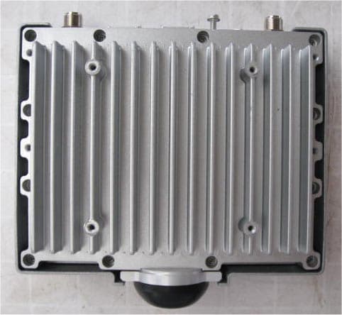
Click to zoom
Application Details
- Equipment Class
- TNB - Licensed Non-Broadcast Station Transmitter
- Date of Grant
- Aug 04, 2009
- Application Purpose
- Original Equipment
- Date of Application
- Jun 23, 2009
- Equipment Note
- Pico Base station transceiver
- Frequency Range
- 3655.00000000 - 3670.00000000
- Company
- Siemens Canada Limited
- Country
- Canada
Documents & Files
Document Text
Text extracted from the exhibit documents filed with the FCC. Open a document above to read the original.
Block Diagram
WiNetworks Ltd. FCC ID:WQE723702 Page 1 of 2 BLOCK DIAGRAM WiMax SoC SQN2130 UART0 PHY FE#1 DAC+Interpolator & ADC 12bit TX1_IQ TX1_SEL_IQ_TX IQ_CLK_1 RX1_IQ RX1_SEL_IQ_RX TX2_IQ TX2_SEL_IQ_TX IQ_CLK_2 RX2_IQ RX2_SEL_IQ_RX SDRAM MSDRAM GPS Receiver TCXO 10Mhz 1PPS Red = Clocks Dark_Blue = Power GPIO 32bit CPU PowerQUICCIII MPC8544 On Board DDR II Memory FLASH PHY FE#2 DAC+Interpolator & ADC 12bit ETH Switch 25M OCS MII Interface RS-232 Con. RF Connector Option A: DC 48Vin Out: 3.3V,6V GPIO RF_DATA 20pin (GPIO) RF IC MIMO 2x2 DC Linear Regulators, Filtering Dig RF PA Vpc PA TCXO Temperature Sensor RF ID GPS ANT. Con. CLK filter/ Buffer RF0 ANT. Con. RF0 ANT. Con. RS-232 Buffer ETH RJ45 Con. PCI Interface UART1 PoE PD Panel Connector 3.3V 6V SPI Dig ID GP ADC/DAC RF_PWR 6V Pico Base-Station Block Diagram On board DC/DC 1V 1.8V 3.3V MII Interface
Cover Letter(s)
Federal Communication Commission Office of Engineering and Technology USA Subject: Application for certification of a pico base station operating in 3.65 - 3.675 GHz band, FCC ID:WQE723702 Dear Gentlemen, Please find attached our application for certification of a pico base station operating in 3.65 - 3.675 GHz band, model name WiN7237, FCC ID:WQE723702, prepared in accordance with FCC Rules, part 90 subpart Z. The product testing and this application for certification were performed by Hermon Laboratories, which is listed by FCC, Registration Numbers 90623, 90624. Hermon Labs responsible person is Mr. Michael Nikishin, tel: 011 972 4626 8440, fax:011 972 4628 8277, e-mail: [email protected]. Sincerely, Shay Chaim Technology manager
Cover Letter(s)
Request for confidentiality June 14, 2009 Equipment Authorisation Division Federal Communications Commission 7435 Oakland Mills Road Columbia, MD 21046 Gentlemen: In regards to the exhibits submitted in support of the application for FCC ID:WQE723702, please classify the following as permanent confidential under the provision of 47 CFR Sections 0.457 and 0.459: 1) RF schematic, file “Schematic_diagram_19456” 2) Parts list, file “Parts_list_19456”. The above material contains trade secrets or technical data, which would customarily be guarded from competitors. We do not want these documents to be accessible to the general public. Sincerely, Shay Chaim Technology manager
External Photos
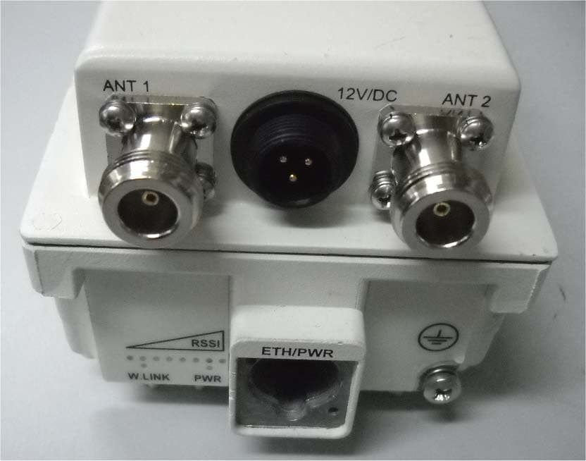
WiNetworks Ltd. FCC ID:WQE723702 Page 1 of 5 EXTERNAL PHOTOGRAPHS This document contains 4 photographs WiNetworks Ltd. FCC ID:WQE723702 Page 2 of 5 Photograph No.1 Base station WiN7237 front view WiNetworks Ltd. FCC ID:WQE723702 Page 3 of 5 Photograph No.2 Base station WiN7237 rear side view WiNetworks Ltd. FCC ID:WQE723702 Page 4 of 5 Photograph No.3 Base station WiN7237 RF connectors WiNetworks Ltd. FCC ID:WQE723702 Page 5 of 5 Photograph No.4 Base station GPS antenna
Operational Description
32 Maskit St. P.O.box 12412 Herzeliya 46733, Israel Contention base protocol 04-10-2008 The FCC mentions the WiMAX technology as an example of restricted contention protocol: “34. Under the Commission’s rules, contention-based protocols can be broadly categorized as either “unrestricted” or “restricted.” ... restricted contention protocols can prevent interference only with other devices incorporating the same protocol. WiMAX, with its scheduling protocol, currently stands as the main example of a restricted contention technology. In its present format, WiMAX technology effectively prevents interference among multiple transmitters on a single WiMAX system. Different WiMAX systems can be coordinated to avoid interfering with each other, thus providing each WiMAX device a “reasonable opportunity to operate.” (FCC 07-99). WiMAX Protocol Brief WiMAX MAC protocol is a centralized protocol in which the base station controls access to the air interface. In the downlink, all decisions related to the allocation of bandwidth to various MSs are made by the BS, which does not require the involvement of the MS. As packets arrive for each terminal, the BS schedules them for the PHY resources, based on their QoS requirements. Once dedicated PHY resources have been allocated for the transmission of the MAC PDU, the BS indicates this allocation to the MS, using the specific MAC messages. In general, WiMAX terminal is a slave to the BS. In the uplink, the MS requests resources by using a contention bases protocol. WiMAX uses a truncated binary exponential backoff algorithm for contention-resolution during polling of user terminals. When it needs to send a bandwidth request the MS first enters a contention resolution phase, if selecting a uniformly distributed random number between 0 and BACKOFF WINDOW. This random value indicates the number of transmission opportunities—allocated resources for multicast/broadcast poll—the MS will wait before sending its bandwidth request. BACKOFF WINDOW is the maximum number of transmission opportunities an MS can wait before sending the pending bandwidth request. If it does not receive a bandwidth allocation based on the UL MAP message within a time window specified by a timer, the MS assumes that its bandwidth request message was lost, owing to collision with another MS, in which case MS increases is backoff window and repeats the process. If bandwidth is still not allocated after a maximum number of retries, the MAC PDU is discarded. Sincerely, Shay Chaim Technology manager
Operational Description
WiNetworks Ltd. FCC ID:WQE723702 Page 1 of 5 OPERATIONAL DESCRIPTION 1.1 Pico BST - Operational description. WiNetworks WiN7200 Pico WiMAX BST is a single sector station used to enhance outdoor and indoor WiMAX coverage and capacity. The unit is easily installable, powered by PoE and supports remote management. WiN7200 provides the full base station functionality necessary for serving a single sector and is available in 2.XGHz and 3.XGHs frequency range. It supports up to 512 subscriber units and its light weight and small footprint allow it to be easily mounted by one person on poles, street lamps or walls. The WiNETWORKS Pico BST is a member of the Win-MAX E family, a line of mobile WiMAX broadband wireless access systems based on the 802.16e mobile WiMAX standard. Win-MAX E systems are designed for robustness and simplicity, offering feature-rich services with low deployment and operation costs, for unmatched operator competitiveness and fast ROI. WiN7200 provides all the functionality necessary to communicate with fixed and mobile subscriber units according to the service criteria and customer Service Level Agreements (SLA). The end-to-end Quality of Service (QoS) ensures the same high quality WiMAX experience is delivered to customers outside or inside his/her home or small office. The WiN7200 is supported by WiNetworks management system – WiNMS. Figure 1. Win7200 Pico BST 1.1.1 Main Features and Capabilities • All outdoor, one-box Pico Base Station solution • GPS synchronization • NLOS • MIMO 2x2 • Small footprint and light weight enables simple installation and deployment by a single person • IEEE802.16e Wave2 Standard Compliance • Backbone Ethernet connectivity via a 10/100 Base-T network interface • Supports fixed and mobile CPEs • Supports 5MHz,7MHz and 10MHz channel bandwidth • Supports different RF options including 2.x, 3.x GHz bands • Traffic classification and connection establishment initiation • Policy-based data switching • Quality of Service (QoS) management • Alarms management • An SNMP agent incorporated into the unit enables extensive In-Band (IB) management of the Base Station and all its registered CPEs • R6 interface to ASN GW profile C 1.2 System Architecture The Pico BST unit receives power and data over PoE. Figure 2. Block Diagram 1.3 Interfaces The unit is installed vertically, where the integrated GPS antenna is located on the top panel (facing the sky). All other connections, including the optional GPS external antenna connections are located on the bottom panel. 1.3.1 Bottom Panel The interface panel supports the antenna, power and Ethernet connections. Figure 3. Pico BST Interface Panel The following table provides a description of the Pico BST bottom panel connectors and ports. Table 1. Bottom Panel Connectors No. Connector Name Connector Type Cable Type Description Connected to 1 ANT1 N type Female RG 214/U RF antenna connection external antenna or Screwed-on omni- directional antenna 2 Console RJ45 Cat5 ETH Low level CLI for WiNetworks technical personnel. RS-232 Computer 3 DC + ETH RJ45 Cat5 ETH DC 1.5A + Ethernet Cat5 PoE data adaptor 4 GND 1 screw ETSI #10 AWG bare copper wire Grounding lug. #10 AWG bare copper wire Central earth ground, Tower or pole chassis 5 GPS (optional) TNC Female RG-59 Base Station Synchronization Optional External GPS antenna 6 ANT2 N type Female RG 214/U RF antenna connection external antenna or Screwed-on omni- directional antenna GND 1.3.2 Top Panel The top panel supports the built-in GPS antenna. (An external GPS antenna can be connected to the bottom panel GPS connector). See section Error! Reference source not found. for more information on GPS antennas and installation criteria. The figure below shows the Pico BST mounted on a pole. Figure 4. Top panel GPS Antenna Integrated GPS antenna
RF Exposure Info
WiNetworks Ltd. FCC ID:WQE723702 RF_Env_evaluation_19456.doc Page 1 of 1 Environmental evaluation and exposure limit according to FCC CFR 47part 1, §1.1307, §1.1310 The calculation was done for confirm compliance with power density limit at 20 cm distance. Limit for power density for general population/uncontrolled exposure is 1 mW/cm 2 for 1500 -100000 MHz frequency range: The power density P (mW/cm 2 ) = P T / 4π r 2 , where P T is the maximum equivalent isotropically radiated power (EIRP). The peak output power of 26.3 dBm with 6 dBi antenna gain corresponds to the equivalent isotropically radiated power (EIRP) of 26.3 dBm + 6 dBi = 32.3 dBm, which is equal to 1698 mW. The power density at 20 cm calculated as follows: 1698 mW / 4π (20 cm) 2 = 0.33 mW/cm 2 < 1 mW/cm 2 General public cannot be exposed to dangerous RF level.
Test Report
Hermon Laboratories Ltd. Harakevet Industrial Zone, Binyamina 30500, Israel Tel. +972-4-6288001 Fax. +972-4-6288277 E-mail: [email protected] Page 1 of 133 Report ID: WINRAD_FCC.19456.doc Date of Issue: 4/23/2009 Electrical 839.01 TEST REPORT ACCORDING TO: FCC CFR 47 PART 90 subpart Z; part 15 subpart B FOR: WiNetworks Ltd. Base station operating in 3.65-3.675 GHz Model: Pico BS WiN7237 This report is in conformity with ISO/ IEC 17025. The "A2LA Accredited" symbol endorsement applies only to the tests and calibrations that are listed in the scope of Hermon Laboratories accreditation. The test results relate only to the items tested. This test report shall not be reproduced in any form except in full with the written approval of Hermon Laboratories Ltd. Report ID: WINRAD_FCC.19456.doc Date of Issue: 4/23/2009 Page 2 of 133 Table of contents 1 Applicant information..................................................................................................................................................... 3 2 Equipment under test attributes .................................................................................................................................... 3 3 Manufacturer information .............................................................................................................................................. 3 4 Test details.................................................................................................................................................................... 3 5 Tests summary.............................................................................................................................................................. 4 6 EUT description............................................................................................................................................................. 5 6.1 General information....................................................................................................................................................... 5 6.2 Ports and lines .............................................................................................................................................................. 5 6.3 Support and test equipment .......................................................................................................................................... 5 6.4 Changes made in the EUT ............................................................................................................................................ 5 6.5 Test configuration.......................................................................................................................................................... 6 6.6 Transmitter characteristics ............................................................................................................................................ 7 7 Transmitter tests according to 47CFR part 90 requirements......................................................................................... 8 7.1 Peak output power test.................................................................................................................................................. 8 7.2 Occupied bandwidth test ............................................................................................................................................. 29 7.3 Emission mask test ..................................................................................................................................................... 46 7.4 Radiated spurious emission measurements................................................................................................................ 63 7.5 Spurious emissions at RF antenna connector test ...................................................................................................... 80 7.6 Frequency stability test.............................................................................................................................................. 101 8 Emissions tests according to 47CFR part 15 subpart B requirements ...................................................................... 103 8.1 Conducted emissions ................................................................................................................................................ 103 8.2 Radiated emission measurements ............................................................................................................................ 107 9 APPENDIX A Test equipment and ancillaries used for tests..................................................................................... 114 10 APPENDIX B Measurement uncertainties................................................................................................................. 116 11 APPENDIX C Test facility description ....................................................................................................................... 117 12 APPENDIX D Specification references ..................................................................................................................... 117 13 APPENDIX E Test equipment correction factors....................................................................................................... 118 14 APPENDIX F Abbreviations and acronyms............................................................................................................... 133 Report ID: WINRAD_FCC.19456.doc Date of Issue: 4/23/2009 Page 3 of 133 1 Applicant information Client name: WiNetworks Ltd. Address: 32 Maskit Street, P.O.Box 12412, Herzeliya 46733, Israel Telephone: +972 9951 9556 Fax: +972 9951 9557 E-mail: [email protected] Contact name: Mr. Shay Chaim 2 Equipment under test attributes Product name: Base station operating in 3.65-3.675 GHz Product type: Transceiver Model(s): Pico BS WiN7237 Receipt date 2/16/…
Text truncated - open the document above for the full version.
Test Setup Photos
WiNetworks Ltd. FCC ID:WQE723702 Page 1 of 10 SETUP PHOTOGRAPHS This document contains 9 photographs WiNetworks Ltd. FCC ID:WQE723702 Page 2 of 10 Photograph No.1 Peak output power, occupied bandwidth, conducted spurious emissions measurement setup WiNetworks Ltd. FCC ID:WQE723702 Page 3 of 10 Photograph No.2 Emission mask measurement setup WiNetworks Ltd. FCC ID:WQE723702 Page 4 of 10 Photograph No.3 Conducted spurious emissions measurement setup WiNetworks Ltd. FCC ID:WQE723702 Page 5 of 10 Photograph No.4 Spurious emissions measurement setup in the anechoic chamber below 30 MHz WiNetworks Ltd. FCC ID:WQE723702 Page 6 of 10 Photograph No.5 Spurious emissions measurement setup in the anechoic chamber in 30 -1000 MHz WiNetworks Ltd. FCC ID:WQE723702 Page 7 of 10 Photograph No.6 Spurious emissions measurement setup in the anechoic chamber above 1000 MHz WiNetworks Ltd. FCC ID:WQE723702 Page 8 of 10 Photograph No.7 Radiated spurious emissions measurement setup at the OATS above 1000 MHz WiNetworks Ltd. FCC ID:WQE723702 Page 9 of 10 Photograph No.8 Frequency stability measurement setup WiNetworks Ltd. FCC ID:WQE723702 Page 10 of 10 Photograph No.9 Conducted emissions measurement on AC line setup
Contact Information
Applicant
Norman Lew(Senior Certification Engineer)
Technical Contact
Hermon Laboratories Ltd.Michael Nikishin
[email protected]+972 4626 8440
Harakevet Industrial zone · Binyamina · Israel
Non-Technical Contact
WiNetworks Ltd.Shay Chaim
[email protected]+972 9951 9556
Test Firm
Hermon Laboratories Ltd.Alexander Usoskin
Technical Specifications
| # | Rule Parts | Frequency Range | Power Output | Emission | Tolerance |
|---|---|---|---|---|---|
| 3 | 9 | 3.65 GHz - 3.67 GHz | 1.28 W | 10M0W7D | 3420 Hz |
Other Applications from Siemens Canada Limited
WQE5237001
Aug 03, 2011Subscriber unit transceiver
Equipment Class
TNB - Licensed Non-Broadcast Station TransmitterWQE523702
Jan 22, 2009Subscriber unit transceiver
Equipment Class
TNB - Licensed Non-Broadcast Station Transmitter