WR926POSMRSAN1Radar Occupancy Sensor
ecobee Incorporated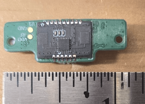
Click to zoom
Application Details
- Equipment Class
- DXX - Part 15 Low Power Communication Device Transmitter
- Date of Grant
- May 15, 2026
- Application Purpose
- Original Equipment
- Equipment Note
- Radar Occupancy Sensor
- Frequency Range
- 24125.00000000 - 24125.00000000
- Company
- ecobee Incorporated
- Country
- Canada
Documents & Files
Document Text
Text extracted from the exhibit documents filed with the FCC. Open a document above to read the original.
Users Manual
Version 1 December 29, 2025 For Models ECB601 and ECB501 only Model: EB-POS24G FCC ID: WR926POSMRSAN1 IC: 7981A-26POSMRSAN1 Confidential 2 Disassembly - Remove Rear Housing 1 2 3 1. Remove the 4 screws holding the backing plate in place 2. Remove rear cover 3. Using a plastic wedge, lift the rear housing away from the front housing Screw Torque 6.0 +/- 0.2 kgf-cm Confidential 3 6.Remove and set aside the two gaskets 7.Detach the speaker wire connector by gently tugging up. 8.Open FFC flex connector drawer 9.Gently tug the FFC flex connector up to detach Disassembly – Gaskets and Connectors FFC Flex Connector Wire connectors Gaskets Confidential 4 Front Housing to Rear Housing Disassembly 1. Pull apart both sub assembly halves. Ensure FPC Cable and speaker connector are lose during disassembly. Confidential 5 Disassembly – Front Housing Radar Board PCBA Connections 1. Open FFC flex connector 2. Remove FFC flex cable from PCBA connector FFC Flex Connector Confidential 6 Front Housing – Radar Board Insertion and removal 1. Ensure orientation of radar board is correct 2. Insert radar board into the LDS frame 3. Reverse the process to remove the radar board Confidential 7 Front Housing – PCBA Connections 1. Insert Radar flex into PCBA connector, check the silk screen line is parallel with connector. 2. Insert Radar FFC flex into connector. 3. Close connector. Confidential 8 6.Insert the two gaskets 7.Connect the speaker wire connector by lining up the connector and gently pushing down. 8.Open FFC flex connector drawer 9.Gently push the FFC flex connector in and close the drawer to latch flex in Assembly – Gaskets and Connectors FFC Flex Connector Wire connectors Gaskets Confidential 9 Front Housing to Rear Housing Assembly 1. Bring both sub assembly halves together as a clamshell. Ensure FPC Cable does not get caught underneath during assembly. Confidential 10 Full Unit Assembly – Rear Cover 1. Place rear cover into opening of housing. 2. Insert and torque 4x screws. 3. Torque screws in the following pattern as labelled below. Torque 6.0 +/- 0.2 kgf-cm 4 3 1 2 Photos for reference purposes only 1 2 3 4 Confidential 11 Regulatory Approvals This Limited Modular Approved device complies with FCC 15.249 & 15.209 rules and RSS-210 requirements. The host device manufacturer is responsible for compliance to any other FCC/ISED rules that apply to the host not covered by the modular transmitter grant certification. The final host device will require Part 15 Subpart B/ICES-003 compliance testing with the modular transmitter installed. This module is not sold separately and is not intended/installed to be used in any host except for Ecobee Inc. Models ECB601 and ECB501 and in case where the module will be integrated in other non-identical hosts in the future, we will expand the LMA to include the new hosts after an appropriate assessment to the FCC/ISED rules. Integration instructions for host device manufacturers can be found below and are compliant with the KDB 996369 D03 OEM Manual v01. Specific Operational Use Conditions The module is tested for mobile RF exposure use conditions. Using the module for portable conditions will require additional assessment though a Class II permissive change or a change in FCC ID through a new application. The host manufacturer installing this module into their product must ensure that the final product complies with the FCC and/or ISED requirements by a technical assessment or evaluation against the FCC and/or ISED rules. The host manufacturer must be aware not to provide information to the end user regarding how to install or remove this RF module in the user’s manual of the end product which integrates this module. The host’s end-user manual shall include all required regulatory information/warning as shown in this manual. The module are not permitted to be used in satellites and aircrafts. Limited Module Procedure This limited module approved transmitter does not have a RF shield over the transmitter portion of the device and the transmitter is not tested in stand-alone configuration The end host shall ensure spurious radiated emissions meets FCC and ISED rules. Integration instructions Confidential 12 RF Exposure Conditions A 20 cm minimum distance must be maintained between the antenna and the users for the host device this module is integrated into. Under such configuration, the FCC radiation exposure limits set forth for an uncontrolled environment can be satisfied. Further RF exposure shall be re- evaluated to the scenario of portable and co-located use. Antenna Antenna is integrated in the RF chip. Tx antenna gain is 3 dBi. No external antenna connection is required for normal function of the radar. User Manual of the End Product In the user manual of the end product, the end user must be informed to keep at least 20 cm separation with the antenna while this end product is installed and operated. The end user must be informed that the FCC radio-frequency exposure guidelines for an uncontrolled environment can be satisfied. The end user must also be informed that any changes or modifications not expressly approved by the manufacturer could void the user’s authority to operate this equipment. Label and compliance information The final end product must be labeled, in a font size of 4pt or greater, in a visible area with the following: Contains FCC ID: WR926POSMRSAN1 Contains IC: 7981A-26POSMRSAN1 Integration instructions Continued Confidential 13 Additional Notice This module is intended for internal use with the specific platform ECB601 and ECB501. The integrator is responsible for the compliance to all the rules that apply to the product into which this certified limited RF module is integrated. Additional testing and certification may be necessary when multiple transmitter are used. A Class II permissive change is required if the module is integrated in different hosts. 1. Radiated field strength must be tested per ANSI C63.10-2020 and comply with FCC Part 1…
Text truncated - open the document above for the full version.
ID Label/Location Info
Report No.: ML303230-RF00Issue Date: April 27, 2026 Megalab Group Inc. – 150 Addison Hall Circle, Aurora, Ontario, L4G 3X8, Canada www.megalabinc.com – (905) 752-1925 This report may not be reproduced, except in full, without prior written approval of Megalab Group Inc. Page 1 of 2 Client:Ecobee Inc. Product Name/Model:EB-POS24G FCC ID:WR926POSMRSAN1 IC:7981A-26POSMRSAN1 Host Label Figure 1: ECB501 Label Report No.: ML303230-RF00Issue Date: April 27, 2026 Megalab Group Inc. – 150 Addison Hall Circle, Aurora, Ontario, L4G 3X8, Canada www.megalabinc.com – (905) 752-1925 This report may not be reproduced, except in full, without prior written approval of Megalab Group Inc. Page 2 of 2 Figure 2: ECB601 Label
Test Setup Photos
Page of Section .Radiated emissions setup photos .Below GHz Setup photos – PRJ0094088 Page of Page of .Above GHz Page of Page of Section .Conducted AC emissions setup photos .General setup Page of .General setup, alternative view END OF REPORT
Test Report
www.nemko.com Nemko Canada Inc., a testing laboratory, is accredited by ANSI National Accreditation Board (ANAB). The tests included in this report are within the scope of this accreditation. The ANAB symbol is an official symbol of the ANSI National Accreditation Board, used under licence. ANAB File Number: AT-3195 (Ottawa); AT-3193 (Pointe-Claire); AT-3194 (Cambridge) FCC 15.249 and RSS-210 Issue 11 B.10; Date: Jan 30, 2026 C h o o s e S c a n d i n a v i a n t r u s t RADIO TEST REPORT Report ID: Project number: REP148536 PRJ0094088 Type of assessment: Final product testing Type of radio equipment: Equipment class: Radar DTS Applicant: Description of product: Ecobee Inc. Radar 24 GHz Occupancy Sensor Module Model(s)/HVIN(s): Product marketing name (PMN): EB-POS24G EB-POS24G FCC identifier: ISED certification number: FCC ID: WR926POSRSAN1 IC: 7981A-26POSMRSAN1 Specifications: FCC 47 CFR Part 15 Subpart C, §15.249 RSS-210 Issue 11, June 2024, Annex B.10 Date of issue: March 18, 2026 Alvin Liu, EMC/RF Specialist Tested by Signature Dhara Patel, EMC/RF Specialist Reviewed by Signature Report reference ID: REP148536 Page 2 of 27 Lab locations Company name Nemko Canada Inc. Facilities Ottawa site: 303 River Road, Ottawa, ON, Canada, K1V 1H2 Tel: +1 613 737 9680 Test site registration number: CA2040 Montréal site: 292 Labrosse Avenue, Pointe-Claire, QC, Canada, H9R 5L8 Tel: +1 514 694 2684 Test site registration number: CA2041 Cambridge site: 1-130 Saltsman Drive, Cambridge, ON, Canada, N3E 0B2 Tel: +1 519 650 4811 Test site registration number: CA0101 Website www.nemko.com Limits of responsibility Note that the results contained in this report relate only to the items tested and were obtained in the period between the date of initial receipt of samples and the date of issue of the report. This test report has been completed in accordance with the requirements of ISO/IEC 17025. All results contained in this report are within Nemko Canada’s ISO/IEC 17025 accreditation. Copyright notification Nemko Canada Inc. authorizes the applicant to reproduce this report provided it is reproduced in its entirety and for use by the company’s employees only. Any use which a third party makes of this report, or any reliance on or decisions to be made based on it, are the responsibility of such third parties. Nemko Canada Inc. accepts no responsibility for damages, if any, suffered by any third party as a result of decisions made or actions based on this report. © Nemko Canada Inc. Report reference ID: REP148536 Page 3 of 27 Table of Contents Table of Contents ......................................................................................................................................................................................................... 3 Report summary ................................................................................................................................................................................. 4 1.1 Test specifications .................................................................................................................................................................................................... 4 1.2 Test methods ............................................................................................................................................................................................................ 4 1.3 Exclusions ................................................................................................................................................................................................................. 4 1.4 Statement of compliance .......................................................................................................................................................................................... 4 1.5 Test report revision history ....................................................................................................................................................................................... 4 Engineering considerations ................................................................................................................................................................. 5 2.1 Modifications incorporated in the EUT for compliance ............................................................................................................................................ 5 2.2 Technical judgment .................................................................................................................................................................................................. 5 2.3 Model variant declaration ........................................................................................................................................................................................ 5 2.4 Deviations from laboratory tests procedures ........................................................................................................................................................... 5 Test conditions ................................................................................................................................................................................... 6 3.1 Atmospheric conditions ............................................................................................................................................................................................ 6 3.2 Power supply range .................................................................................................................................................................................................. 6 Information provided by the applicant ................................................................................................................................................ 7 4.1 Disclaimer ................................…
Text truncated - open the document above for the full version.
Test Report
Date (03/17/2026) Dear Sir or Madam, The antennas for EB-POS24G uses a chip. There is one transmit antenna and one receiving antenna that are all internal to the Radar chip. Integrated Tx antenna type and shape is not provided by the manufacturer; Tx antenna gain is 3 dBi. The Radar chip does not provide any means for external antenna connection. Yours sincerely, Name: John Russomanno Title: Senior Engineering Technologist CET
RF Exposure Info
Report No.: ML303230-RF00Issue Date: April 27, 2026 Megalab Group Inc. – 150 Addison Hall Circle, Aurora, Ontario, L4G 3X8, Canada www.megalabinc.com – (905) 752-1925 This report may not be reproduced, except in full, without prior written approval of Megalab Group Inc. Page 1 of 5 Client:Ecobee Inc. Product Name/Model:EB-POS24G FCC ID:WR926POSMRSAN1 Reference7981A-26POSMRSAN1 FCC RF Exposure Where the Device Under Test (DUT) can be shown to meet the requirements for an exemption pursuant to FCC 47 CFR §1.1307(b)(3), an evaluation is not required with respect to the limits on human exposure to RF emissions provided in FCC 47 CFR §1.1310. 1.Determination of Exemption As per 47 CFR §1.1307(b)(3), for single RF sources (i.e., any single fixed RF source, mobile device, or portable device), a single RF source is exempt if: A.1-mW Test Exemption: The available maximum time-averaged power is no more than 1 mW, regardless of separation distance. This exemption may not be used in conjunction with other exemption criteria other than those in paragraph (b)(3)(ii)(A) of this section. Medical implant devices may only use this exemption and that in paragraph (b)(3)(ii)(A); B.SAR-Based Exemption: The available maximum time-averaged power or effective radiated power (ERP), whichever is greater, is less than or equal to the threshold P th (mW) described in the following formula. This method shall only be used at separation distances (cm) from 0.5 centimeters to 40 centimeters and at frequencies from 0.3 GHz to 6 GHz (inclusive). P th is given by: ( ) = ( 20 ⁄ ) ≤20 20 < ≤40 Where = − 60 And ( ) = 2040 0.3 ≤ <1.5 3060 1.5 ≤ ≤6 d = the minimum separation distance (cm) in any direction from any part of the device antenna(s) or radiating structure(s) to the body of the device user. Report No.: ML303230-RF00Issue Date: April 27, 2026 Megalab Group Inc. – 150 Addison Hall Circle, Aurora, Ontario, L4G 3X8, Canada www.megalabinc.com – (905) 752-1925 This report may not be reproduced, except in full, without prior written approval of Megalab Group Inc. Page 2 of 5 C.MPE-Based Exemption: Using Table 1 and the minimum separation distance (R in meters) from the body of a nearby person for the frequency (f in MHz) at which the source operates, the ERP (watts) is no more than the calculated value prescribed for that frequency. For the exemption in Table 1 to apply, R must be at least λ/2π, where λ is the free-space operating wavelength in meters. If the ERP of a single RF source is not easily obtained, then the available maximum time- averaged power may be used in lieu of ERP if the physical dimensions of the radiating structure(s) do not exceed the electrical length of λ/4 or if the antenna gain is less than that of a half-wave dipole (1.64 linear value). Table 1 of § 1.1307(b)(3)(i)(C) - Single RF Sources Subject to Routine Environmental Evaluation RF SourceFrequency (MHz) Threshold ERP (Watts) 0.3-1.341,920 R 2 1.34-303,450 R 2 /f 2 30-3003.83 R 2 300-1,5000.0128 R 2 f 1,500-100,00019.2 R 2 Where R is the separation distance in meters and f is in MHz 2.RF Exposure Evaluation The DUT is a mobile device designed to be used in such a way that a separation distance of at least 20 centimeters is normally maintained between the RF source's radiating structure and the body of the user or nearby persons. The EUT contains 24,000 – 24,250 MHz transmitter. EIRP exemption threshold was calculated using the lowest operating frequency for each transmitter; the lower frequency resulted in a lower exemption limit. ERP exemption threshold was calculated using the lowest operating frequency for each transmitter; the lower frequency resulted in a lower exemption limit. 2.1DUT RF Output Power Highest power (peak or average) for each operation band was used in the RF exposure evaluation. TransmitterOperation Band (MHz) EIRP (dBm) ERP (dBm) Max ERP (W) Minimum Separation Distance (cm) Radar24,000 –24,25013.110.950.012420 Note: Report No.: ML303230-RF00Issue Date: April 27, 2026 Megalab Group Inc. – 150 Addison Hall Circle, Aurora, Ontario, L4G 3X8, Canada www.megalabinc.com – (905) 752-1925 This report may not be reproduced, except in full, without prior written approval of Megalab Group Inc. Page 3 of 5 1.ERP (dBm) = EIRP – 2.15 2.ERP (W) = 10^((ERP(dBm) – 30)/10) 3.See Section 7.6 of test report for Field Strength data. 2.2MPE-Based Exemption The EUT contains 24,000 – 24,250 MHz transmitter. ERP exemption threshold was calculated using the lowest operating frequency for the transmitter; the lower frequency resulted in a lower exemption limit. Evaluation Frequency (MHz) Minimum Required Separation Distance (λ/2π) (cm) Threshold ERP (W) DUT Maximum ERP (W) 24,1250.1990.7680.0124 Note: λ/2π = (3x10 8 m/s) / (2 * 3.14* f (Hz)) in meters Threshold ERP = 19.2 * 0.2 2 = 0.768 The DUT separation distance is greater than the Minimum Required Separation Distance. And the transmitter operates below its applicable Threshold ERP Limit; thus, the RF Exposure Exemption requirement is met. According to 47 CFR §1.1307(b)(3)(i)(B), this device complies with the RF exposure test exemption. 3.Host RF Exposure Evaluation The host is a mobile device designed to be used in such a way that a separation distance of at least 20 centimeters is normally maintained between the RF source's radiating structure and the body of the user or nearby persons. ERP exemption threshold was calculated using the lowest operating frequency for each transmitter; the lower frequency resulted in a lower exemption limit. 3.1Host Transmitter RF Output Power The host contains 902 – 928 MHz FHSS/Hybrid transmitters, 2400 – 2483.5 MHz DTS/FHSS transmitters, 5.2 GHz and 5.8 GHz WLAN transmitters. The table below shows the type of transmitter, operation band, max ERP, and minimum separation distance of the host transmitters: Host Transmitters TransmitterOperation Band (MHz) Co…
Text truncated - open the document above for the full version.
Internal Photos
Report No.: ML303230-RF00Issue Date: March 23, 2026 Megalab Group Inc. – 150 Addison Hall Circle, Aurora, Ontario, L4G 3X8, Canada www.megalabinc.com – (905) 752-1925 This report may not be reproduced, except in full, without prior written approval of Megalab Group Inc. Page 1 of 1 Client:Ecobee Inc. Product Name/Model:EB-POS24G FCC ID:WR96POSMRSAN1 IC:7981A-26POSMRSAN1 Internal Photos Figure 1– Top view Figure 2 – Bottom view Note: Antenna of the transmitter is within the Radar’s chip.
ID Label/Location Info
Report No.: ML303230-RF00Issue Date: March 23, 2026 Megalab Group Inc. – 150 Addison Hall Circle, Aurora, Ontario, L4G 3X8, Canada www.megalabinc.com – (905) 752-1925 This report may not be reproduced, except in full, without prior written approval of Megalab Group Inc. Page 1 of 3 Client:Ecobee Inc. Product Name/Model:EB-POS24G FCC ID:WR926POSMRSAN1 IC:7981A-26POSMRSAN1 Host External Photos Figure 1– ECB601: Top and left view Figure 2 – ECB601: Top and right view Report No.: ML303230-RF00Issue Date: March 23, 2026 Megalab Group Inc. – 150 Addison Hall Circle, Aurora, Ontario, L4G 3X8, Canada www.megalabinc.com – (905) 752-1925 This report may not be reproduced, except in full, without prior written approval of Megalab Group Inc. Page 2 of 3 Figure 3 – ECB601: Back view with I/O ports Figure 1– ECB501: Top and left view Report No.: ML303230-RF00Issue Date: March 23, 2026 Megalab Group Inc. – 150 Addison Hall Circle, Aurora, Ontario, L4G 3X8, Canada www.megalabinc.com – (905) 752-1925 This report may not be reproduced, except in full, without prior written approval of Megalab Group Inc. Page 3 of 3 Figure 2 – ECB501: Top and right view Figure 3 – ECB501: Back view with I/O ports
Attestation Statements
Covered Equipment Certification Attestation Letter 3/17/2026 Nemko North America, Inc. 303 River Road Ottawa K1V 1H2 Canada ATTN.: Reviewing Engineer FCC ID: WR926POSMRSAN1 Ecobee Inc(“the applicant”) certifies that the equipment for which authorization is sought is not “covered” equipment prohibited from receiving an equipment authorization pursuant to section 2.903 of the FCC rules. This includes certifying that the equipment for which authorization is sought does not include cybersecurity or anti-virus software produced or provided by Kaspersky Lab, Inc. or any of its successors and assignees, including equipment with integrated Kaspersky Lab, Inc. (or any of its successors and assignees) cybersecurity or anti-virus software pursuant to DA-24-886 and KDB 986446 D01 Covered Equipment Guidance section B(2a). Device is inherently compliant based on hardware limitations or software controls. Note: If the equipment for which the applicant seeks authorization is produced by any of the entities identified on the current Covered List, the applicant should include an explanation on why the equipment is not “covered” equipment. Ecobee(“the applicant”) certifies that, as of the date of the filing of the application, the applicant is not identified on the Covered List as an entity producing “covered” equipment. Signed: Printed name: John Russomanno Title: Senior Engineering Technologist CET Company Name: Ecobee Inc Date: 3/17/2026
ID Label/Location Info
207 Queens Quay. Suite 600 Toronto, ON. M5J 1A7 Toll Free 1.877.932.6233, Int. 1.647.428.2220, [email protected] Radar Board Product label Due the size of the of the transmitter, a removable label is placed on the device. Model name and certification numbers are in the Compliance Insert and User Manual.
External Photos
Report No.: ML303230-RF00Issue Date: March 23, 2026 Megalab Group Inc. – 150 Addison Hall Circle, Aurora, Ontario, L4G 3X8, Canada www.megalabinc.com – (905) 752-1925 This report may not be reproduced, except in full, without prior written approval of Megalab Group Inc. Page 1 of 3 Client:Ecobee Inc. Product Name/Model:EB-POS24G FCC ID:WR926POSMRSAN1 IC:7981A-26POSMRSAN1 Host External Photos Figure 1– ECB601: Top and left view Figure 2 – ECB601: Top and right view Report No.: ML303230-RF00Issue Date: March 23, 2026 Megalab Group Inc. – 150 Addison Hall Circle, Aurora, Ontario, L4G 3X8, Canada www.megalabinc.com – (905) 752-1925 This report may not be reproduced, except in full, without prior written approval of Megalab Group Inc. Page 2 of 3 Figure 3 – ECB601: Back view with I/O ports Figure 1– ECB501: Top and left view Report No.: ML303230-RF00Issue Date: March 23, 2026 Megalab Group Inc. – 150 Addison Hall Circle, Aurora, Ontario, L4G 3X8, Canada www.megalabinc.com – (905) 752-1925 This report may not be reproduced, except in full, without prior written approval of Megalab Group Inc. Page 3 of 3 Figure 2 – ECB501: Top and right view Figure 3 – ECB501: Back view with I/O ports
External Photos
Report No.: ML303230-RF00Issue Date: March 23, 2026 Megalab Group Inc. – 150 Addison Hall Circle, Aurora, Ontario, L4G 3X8, Canada www.megalabinc.com – (905) 752-1925 This report may not be reproduced, except in full, without prior written approval of Megalab Group Inc. Page 1 of 1 Client:Ecobee Inc. Product Name/Model:EB-POS24G FCC ID:WR926POSMRSAN1 IC:7981A-26POSMRSAN1 External Photos Figure 1– Top view Figure 2 – Bottom view Note: Antenna of the transmitter is within the Radar’s chip.
Cover Letter(s)
Date (23/03/2026) Federal Communications Commission Equipment Authorization Branch 7435 Oakland Mills Road Columbia, MD 21046 Limited Modular Approval Request FCC ID: WR926POSMRSAN1 The following attestation addresses the requirements to support modular approval: Modular approval requirement Yes (provide brief statement)No * (a) The radio elements must have the radio frequency circuitry shielded. Physical components and tuning capacitor(s) may be located external to the shield, but must be on the module assembly No. Device is a radar and antennas are on the radar chip. (b) The module must have buffered modulation/data inputs to ensure that the device will comply with Part 15 requirements with any type of input signal Yes, implemented as on-chip FIFO. (c) The module must contain power supply regulation on the module Yes. The module has an LDL onboard to covert 3.3 VDC to 1.8 VDC. (d) The module must contain a permanently attached antenna, or contain a unique antenna connector, and be marketed and operated only with specific antenna(s), per Sections 15.203, 15.204(b), 15.204(c), 15.212(a), 2.929(b) Yes, antennas are on chip. No provisions are available for external antenna connection. (e) The module must demonstrate compliance in a stand-alone configuration No. Module was tested in its intended host. The radar CANNOT be tested as stand alone. (f) The module must be labelled with its permanently affixed FCC ID label, or use an electronic display (See KDB Publication 784748 about labelling requirements) Yes. The module is labelled with a temporary label due to its small size as allowed by FCC KDB 784748; the FCC ID is in the User Manual. (g) The module must comply with all specific rules applicable to the transmitter. The grantee must provide comprehensive instructions to explain compliance requirements Yes. Modular approval requirement Yes (provide brief statement)No * (h) The module must comply with RF exposure requirements Yes The module does not meet the RF shielding, and is not tested in Stand-Alone configuration requirement. This LMA application is limited to the specific hosts from Ecobee Inc’s Thermostats, Model: ECB501 and ECB601. The module was tested in host model ECB601 (and represents ECB501 due to same main PCB and form factor). A Class II permissive change is required if the module is integrated in different hosts. Sincerely, Signed: Name: Min Xie Title: Sr. EMC/RF Project Engineer Company: Megalab Group Inc. On behalf of Ecobee Inc.
Cover Letter(s)
March 13, 2026 Nemko North America, Inc. 303 River Road Ottawa, Ontario, Canada K1V 1H2 REQUEST FOR CONFIDENTIALITY - FCC FCC ID: WR926POSMRSAN1 Pursuant to Sections 0.457(d) and 0.459 of the Commission’s Rules and FCC Guidance document 726920, we hereby request permanent confidential treatment of exhibits identified as such in the table below and request they are permanently withheld from public review based on the documents containing trade secrets and proprietary information not customarily released to the public. The public disclosure of this information might be harmful to the applicant and provide unjustified benefits to its competitors. Exhibit Type of Confidentiality Requested Block Diagrams ☒ Permanent ☐ Short Term External Photos ------------------ ☐ Short Term Internal Photos ☐ Permanent* ☐ Short Term Operation Description ☒ Permanent ☐ Short Term Parts List & Placement/BOM ☒ Permanent ☐ Short Term Tune-Up Procedure ☐ Permanent ☐ Short Term Schematic Diagrams ☒ Permanent ☐ Short Term Test Setup Photos ------------------ ☐ Short Term User’s Manual ☐ Permanent* ☐ Short Term Sincerely, Signed: Printed name: John Russomanno Title: Senior Engineering Technologist CET Company Name: Ecobee Inc.
Cover Letter(s)
17/03/2026 Nemko North America, Inc. 303 River Road Ottawa, Ontario, Canada K1V 1H2 AUTHORITY TO ACT AS AGENT – FCC and ISED On our behalf, I appoint Min Xie of MegaLab Group Inc, 150 Addison Hall Circle, Aurora, Ontario, L4G 3X8, Canada; 905-752-1925, to act as our agent in the preparation of this application for equipment certification. I certify that submitted documents properly describe the device or system for which equipment certification is sought. I also certify that each unit manufactured, imported or marketed, as defined in FCC and ISED Canada’s regulations will have affixed to it a label identical to that submitted for approval with this application. In signing this letter, Applicant certifies that neither the applicant nor any party to the application is not subject to a denial of Federal benefits, that include FCC benefits, pursuant to Section 5301 of the Anti-Drug Abuse Act of 1988, 21 U.S.C. § 862 because of a conviction for possession or distribution of a controlled substance. See 47 CFR 1.2002(b) for the definition of a "party" for these purposes. For instances where our authorized agent signs the application for certification on our behalf, I acknowledge that all responsibility for complying with the terms and conditions for certification, as specified by Nemko North America Inc., still resides still resides with us. Sincerely, Printed name: John Russomanno Title: Senior Engineering Technologist CET Company Name: Ecobee Inc
Attestation Statements
* the applicant must designate a contact located in the United States for purposes of acting as the applicant’s agent for service of process, regardless of whether the applicant is a domestic or foreign entity. An applicant located in the United States may designate itself as the agent for se…
Text truncated - open the document above for the full version.
Contact Information
Applicant
John Russomanno(Engineering Technologist (CET))
[email protected]Fax: 866-592-7344
Technical Contact
Generac Power System Inc.Jeffery Jonas
S45 W29290 Hwy. 59, Waukesha Wisconsin · P.O. Box 53189 · United States
Test Firm
Nemko Canada Inc. (Ottawa)Charles Neal
[email protected]Fax: 613-737-9691
Technical Specifications
| # | Rule Parts | Frequency Range | Power Output |
|---|---|---|---|
| 1 | 15C | 24.13 GHz - 24.13 GHz | - |
Other Applications from ecobee Incorporated
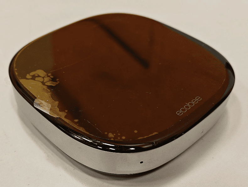
WR925SC1AG0ARC
Apr 06, 2026Radar Occupancy Sensor
Equipment Class
FDS - Part 15 Field Disturbance Sensor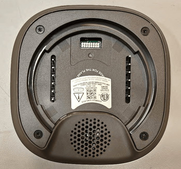
WR92025AA2060G
Feb 20, 2026Smart Thermostat
Equipment Class
NII - Unlicensed National Information Infrastructure TXWR9202428847PR
Oct 14, 2024Smart Thermostat
Equipment Class
DSS - Part 15 Spread Spectrum Transmitter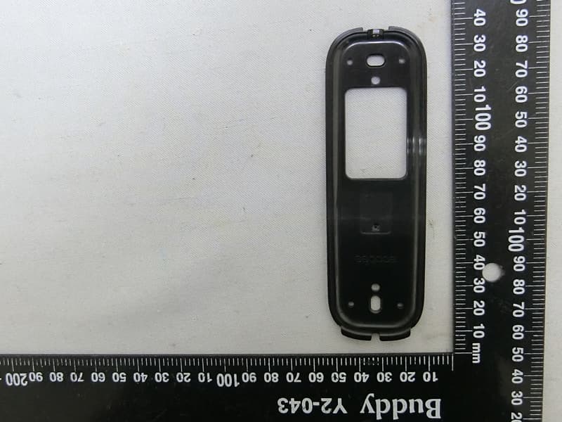
WR932181716523
Oct 16, 2023Video doorbell
Equipment Class
DXX - Part 15 Low Power Communication Device Transmitter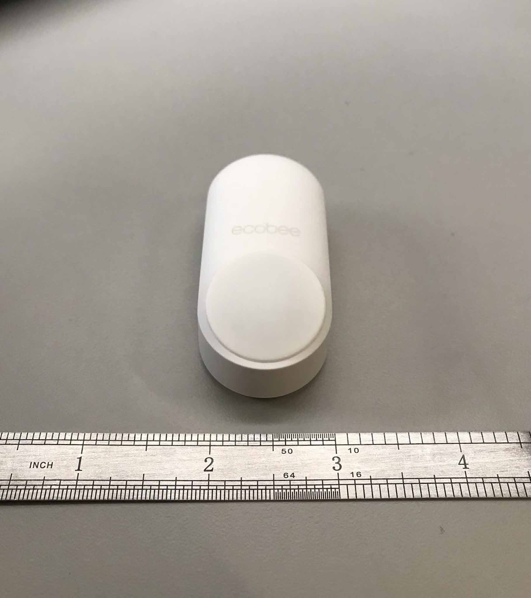
WR968118104116
Mar 05, 2020SmartSensor for doors and windows
Equipment Class
DSS - Part 15 Spread Spectrum Transmitter