WSX-IGM-1001DLipid profile and glucose measuring system for self testing
OSANG Healthcare Co., Ltd.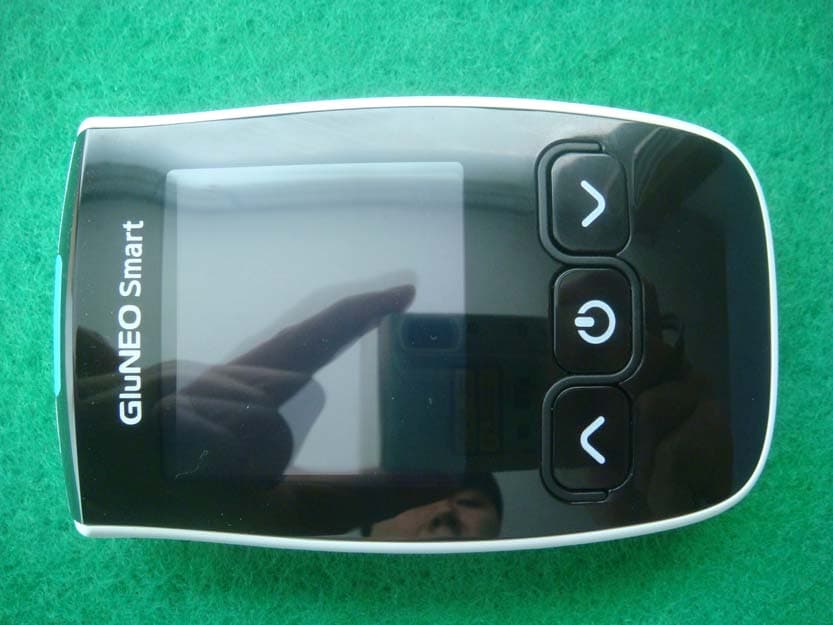
Click to zoom
Application Details
- Equipment Class
- DTS - Digital Transmission System
- Date of Grant
- Oct 15, 2014
- Application Purpose
- Original Equipment
- Date of Application
- Oct 15, 2014
- Equipment Note
- Lipid profile and glucose measuring system for self testing
- Frequency Range
- 2402.00000000 - 2480.00000000
- Company
- OSANG Healthcare Co., Ltd.
- Country
- South Korea
Documents & Files
Document Text
Text extracted from the exhibit documents filed with the FCC. Open a document above to read the original.
Users Manual
INFOPIA CO., LTD Page 1 UM-M (Rev.0) Operation Manual Dear IGM-1001D Blood Glucose Monitoring System Owner, Thank you for choosing the IGM-1001D Blood Glucose Monitoring System. This manual contains everything you need to know about your new glucometer and how it works. Please take a moment to read the instructions carefully. We understand that self-testing of blood glucose level provides a way to control your diabetes and may give you peace of mind by testing regularly. As a result, IGM-1001D has been developed to provide you with a fast and accurate reading in a convenient and simple process. Our goal for the IGM-1001D Blood Glucose Monitoring System is to provide you with the best quality healthcare products coupled with superior customer service. Always consult with your healthcare professional, before making any changes to your diabetes management. The IGM-1001D Blood Glucose Monitoring System is for in-vitro diagnostic use only. Customer Service is available 24 hours a day, 7 days a week, and 365 days a year. Please call customer support center in your local area. Important Information The IGM-1001D Blood Glucose Monitoring System is intended for use outside the body (in-vitro diagnostic use only). It should be used only for testing blood glucose and only with fresh capillary whole blood samples. It should not be used for the diagnosis of diabetes. Consult with your physician or diabetic healthcare professional about daily management of your diabetes and proper use of the glucometer. Please pay close attention when handling blood. Improper procedures may cause serious hazards to your health. The IGM-1001D Blood Glucose Monitoring System contains small parts, which could be a choking hazard for children if swallowed. Test Principle IGM-1001D blood glucose test strip is the bio-sensor which has been made by the FAD-dependent glucose dehydrogenase(enzyme). FAD-GDH(enzyme) quantitatively reacts with the glucose in the whole blood and the mediator. At this moment, mediator Fe(CN) 6 3- is reduced to Fe(CN) 6 4- . This Fe(CN) 6 4- generated by the reaction is re-oxidized on carbon electrode, for which the method is called amperometry. The measured oxidation current exists in proportion to the glucose concentration in the whole blood. WARNING: 1. All parts of the kit are considered bio-hazardous and can potentially transmit infectious diseases, even after you have taken cleaning and disinfection measures. 2. Always use a new, sterile lancet. Lancets are for single use only. 3. Avoid getting hands lotions, oil, dirt or debris in and/or on the lancets and reusable lancing device. 4. Please refer to page 12 for cleaning and disinfecting IGM- 1001D Blood Glucose Monitoring System. 5. Do not change your medication based on the IGM-1001D meter test results without contacting your physician or healthcare professional first. 6. Do not assemble or disassemble the blood glucose test meter 7. Keep out of direct sunlight. CAUTION: Following list of IMPORTANT SAFETY INSTRUCTIONS provided: 1. Close supervision is necessary when equipment is used by, on, or near children, handicapped persons or invalids. 2. Do not place the equipment in liquid, nor put it where it could fall into liquid. If the equipment becomes wet, remove the batteries and dry the device. 3. Use the equipment only for the purpose described in the instructions for use. 4. Do not use accessories which are not supplied or recommended by the manufacturer. 5. Do not place anything on top of the equipment. INFOPIA CO., LTD Page 2 UM-M (Rev.0) Learning the System Intended use of Blood Glucose Test Meter The IGM-1001D Blood Glucose Monitoring System is intended for use outside the body only (in-vitro diagnostic use) and self-testing. Recorded results make it easier for your doctor to access your metabolic control. However, the self-testing should not take the place of overall diabetes management assessment from your doctor. It should be used for testing blood glucose (sugar) only with fresh capillary whole blood samples. IGM-1001D Blood Glucose Monitoring System is intended for use in places like home and in professional setting to monitor blood glucose levels. CAUTION - Do not use system for any other purpose than blood glucose test. - Cholesterol concentrations > 500 mg/dL or triglyceride concentrations > 3,000 mg/dL may produce elevated reading. - Icodextrin does not interfere with this version of IGM-1001D test strips. - Do not use during or soon after xylose absorption testing. Xylose in the blood will cause interference. - Before using any product, please read all instructions. - Consult with your physician or diabetic healthcare professional about daily management of your diabetes and proper use of the glucometer. If you have any questions about the IGM-1001D product, please contact your local representative. WARNING - Before using IGM-1001D system, read all instructions in this manual, and practice for accurate and safe test. You should have commentary recommendation from your diabetes care professional for the proper use of the meter and daily management of your diabetes. - If you think your blood glucose results are too low or too high, or if the results are doubtful, please contact your doctor. - If your blood glucose result is unusually low or high, or you do not feel the result is correct, repeat the test again with a new test strip. - If the results are still inconsistent, please consult with your physician before making any decision in controlling your diabetes. Table of Contents Learning the System Intended use of blood glucose test meter IGM-1001D kit components IGM-1001D meter IGM-1001D meter Display IGM-1001D test strip --- 2 --- 3 --- 3 --- 3 --- 4 Before Testing: Setting your meter Auto-coding function Performing a control solution test --- 4 --- 5 --- 5 Performing Your Test: Testing Blood - preparation Performing a blood test with your finger tip Test strip ejector function --- 6 --- 7 --- 9 Reviewing Your Results: Review…
Text truncated - open the document above for the full version.
External Photos
SK Tech Co., Ltd. Page 1 of 4 Photographs of EUT External view SK Tech Co., Ltd. Page 2 of 4 SK Tech Co., Ltd. Page 3 of 4 SK Tech Co., Ltd. Page 4 of 4 Battery cover opened
ID Label/Location Info
ID Label Location & Sample LABEL LOCATION: Label will be attached to the Rear of the product LABEL Drawing:
Internal Photos
SK Tech Co., Ltd. Page 1 of 4 Photographs of EUT Cover opened SK Tech Co., Ltd. Page 2 of 4 Main board Bluetooth LE Module SK Tech Co., Ltd. Page 3 of 4 LCD SK Tech Co., Ltd. Page 4 of 4 Bluetooth LE Module & Antenna PCB Antenna
RF Exposure Info
RF Exposure requirements Product name Blood Glucose Monitoring System Model number IGM‐1001D FCC ID WSX‐IGM‐1001D Radio specification 2.4 GHz Antenna Internal PCB antenna Power source DC 3 V(CR2032 Coin battery x 2 EA) According to the KDB 447498, the following standalone SAR test exclusion was considered to qualify for the SAR test exclusion. Tx frequency range 2402 MHz ‐ 2480 MHz Device category Handheld portable device Maximum conducted output power 0.37 mW (‐4.35 dBm) @ 2402 MHz Limit 10 mW (distance = 5 mm) RF power output (measured): unit: mW Operating frequency Data rate 2402 MHz 2440 MHz 2480 MHz 1 Mbps(Bluetooth LE) 0.37 0.27 0.21 SAR test exclusion thresholds: [(max. power of channel, mW) / (min. separaƟon distance, mm ] · √f (GHz) ≤ 3.0 for 1‐g SAR and ≤ 7.5 for 10‐g extremity SAR MHz 5 10 15 20 25 293035404550 test separation distance (mm) 2450 10 19 29 38 48 565767778696 SAR test exclusion threshold (mW) The source‐based time‐averaged maximum conducted output power of the RF channel is less than 10 mW, and the minimum separation distance of 5 mm can be achieved. Therefore the transmitter complies with the RF exposure requirements and the SAR is not required.
Test Report
SK Tech Co., Ltd. Report No.: SKT-RFC-140008 Page 2 of 21 Revision History of Report Rev. Revisions Effect pageReviewed by Date - Initial issue All Jongsoo Yoon October 10, 2014 SK Tech Co., Ltd. Report No.: SKT-RFC-140008 Page 3 of 21 TABLE OF CONTENTS 1 Summary of test results ................................................................................................. 4 2 Description of equipment under test (EUT) .................................................................. 5 3 Test and measurement conditions ................................................................................ 6 3.1. Test configuration (arrangement of EUT) ................................................................................ 6 3.2. Description of support units (accessory equipment)................................................................ 6 3.3. Interconnection and I/O cables................................................................................................ 6 3.4. Measurement Uncertainty (U) ................................................................................................. 6 3.5. Test date .................................................................................................................................. 6 4 Facilities and accreditations .......................................................................................... 7 4.1. Facilities................................................................................................................................... 7 4.2. Accreditations .......................................................................................................................... 7 4.3. List of test and measurement instruments............................................................................... 7 5 Test and measurements ................................................................................................. 8 5.1. Antenna requirement ............................................................................................................... 8 5.2. 6 dB bandwidth........................................................................................................................ 9 5.3. Maximum peak output power ................................................................................................ 11 5.4. Spurious emissions, Band edge, and Restricted bands ........................................................ 13 5.5. Peak power spectral density.................................................................................................. 20 SK Tech Co., Ltd. Report No.: SKT-RFC-140008 Page 4 of 21 1 Summary of test results Requirement CFR 47 Section Result Antenna Requirement 15.203, 15.247(b)(4) Meets the requirements 6dB Bandwidth 15.247(a)(2) Meets the requirements Maximum Peak Output Power 15.247(b)(3), (4) Meets the requirements Spurious Emission, Band Edge, and Restricted bands 15.247(d), 15.205(a), 15.209(a) Meets the requirements Peak Power Spectral Density 15.247(e) Meets the requirements AC power line Conducted emissions 15.207(a) N/A* * Not required, the EUT is only battery powered(3 V coin battery) SK Tech Co., Ltd. Report No.: SKT-RFC-140008 Page 5 of 21 2 Description of equipment under test (EUT) Product: Blood Glucose Monitoring System Model: IGM-1001D Serial number: None (prototype) Model differences: Model name Difference Tested (checked) IGM-1001D Fully tested model that was provided by the applicant Technical data: Power source DC 3 V (CR2032 battery x 2) Local Oscillator or X-Tal 32.768 kHz, 32 MHz Transmit Frequency 2402 MHz ~ 2480 MHz (40 channels, Bluetooth LE only) Antenna Type Integral PCB antenna(gain: 0 dBi) Type of Modulation GFSK RF Output power -4.35 dBm PEAK(measured) Note: 1) The test report for the compliance with FCC Part 15B as a digital device was issued with other test report number I/O port Type Q'ty Remark USB Jack 1 Test strip For the measurements of blood glucose 1 Modification of EUT during the compliance testing: none SK Tech Co., Ltd. Report No.: SKT-RFC-140008 Page 6 of 21 3 Test and measurement conditions 3.1. Test configuration (arrangement of EUT) The measurements were taken in continuous transmitting mode without off-time intervals. For controlling the EUT as TEST MODE, the test program and the cable assembly were provided by the applicant. USB I nterface TEST JIG EU T PC Debug The measurements were taken in TEST MODE provided by the applicant for controlling the EUT. ■ Software version (Smart RF Studio 7): 1.16.1 ■ Software manufacturer:Texas Instruments. ■ Power setting: 0 dBm 3.2. Description of support units (accessory equipment) The following support units or accessories were used to form a representative test configuration during the tests. # Equipment Manufacturer Model No. Serial No. 1 PC DELL INC. 7XH86BX 17261795085 2 TEST JIG - - - Note: For radiated spurious emission measurements, the measurements were performed without PC after setting the radio module to TEST MODE. 3.3. Interconnection and I/O cables The following support units or accessories were used to form a representative test configuration during the tests. Start End Cable # Name I/O port Name I/O port length (m) shielded (Y/N) 1 EUT Debug TEST JIG - 0.2 N 2 TEST JIG USB PC USB 1.0 N Note: 1) All the equipment/cables were placed in the worst-case configuration to maximize the emission during the test. 3.4. Measurement Uncertainty (U) Measurement Item Combined Standard Uncertainty Uc Expanded Uncertainty U = k Uc (k = 2) Conducted RF power ±1.49 dB ±2.98 dB Radiated disturbance ±2.30 dB ±4.60 dB Conducted disturbance ±1.96 dB ±3.92 dB 3.5. Test date Date Tested September 19, 2014 – October 1, 2014 SK Tech Co., Ltd. Report No.: SKT-RFC-140008 Page 7 of 21 4 Facilities and accreditations 4.1. Facilities All of the measurements described in this report were performed at SK Tech Co., Ltd Site I: 820-2, Wolmoon-ri, Wabu-up, Namyangju-si, Kyunggi-do, Kor…
Text truncated - open the document above for the full version.
Contact Information
Applicant
Dae Sup Shin
Test Firm
SK Tech Co., LTD.Yoon Jongsoo
Technical Specifications
| # | Rule Parts | Frequency Range | Power Output |
|---|---|---|---|
| 1 | 15C | 2.40 GHz - 2.48 GHz | 370.00 µW |
Other Applications from OSANG Healthcare Co., Ltd.
WSX-RPM-A432
Nov 05, 2014Robotic Packing Machine
Equipment Class
DXX - Part 15 Low Power Communication Device Transmitter