WSYJJ-RC-ARemote control
GIANT ALARM SYSTEM CO., LTD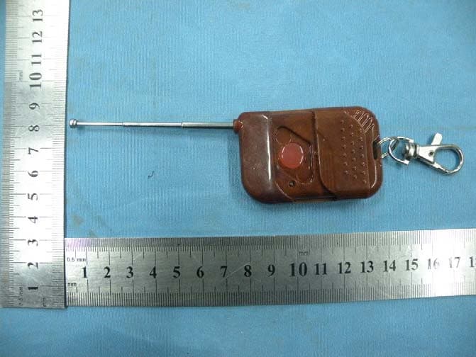
Click to zoom
Application Details
- Equipment Class
- DSC - Part 15 Security/Remote Control Transmitter
- Date of Grant
- Jan 11, 2011
- Application Purpose
- Original Equipment
- Date of Application
- Jan 11, 2011
- Equipment Note
- Remote control
- Frequency Range
- 433.92000000 - 433.92000000
- Company
- GIANT ALARM SYSTEM CO., LTD
- Country
- China
Documents & Files
Document Text
Text extracted from the exhibit documents filed with the FCC. Open a document above to read the original.
Users Manual
INSTRUCTION OF SINGLE CHANNEL REMOTE CONTROL SYSTEM z VOLTAGE:12V/24V optional z FREQUENCY:433.92MHZ±100K z CHANNEL:1 z CHARACTERISTICS: APPLICATION RANGE: gard agaist theft, gate opener, motor etc. This system can memory about 100 remotes. If the receiver is not in the state of learning new code, but it gets same code(and same format) of the remote, learning LED will flash to indicate that the remote can work with the receiver. z WORKING INSTRUCTION:press the button, dry contact activates 2 minutes. In the first 5 seconds, any other control signals will be invalid. After 5 seconds if you press the button again, dry contact will disconnect. If there’s no operation in the first 2 minutes, dry contact will open 2 minutes later. LEARNING CODE: Short press learning button on PCB, LED will flash and keep lighting, now you can learn new code. If the code is learnt successfully, LED will turn off. If it doesn’t learn new code in 5 seconds, LED will turn off and stop learning. z REMOVE CODE: Press learning button for 10 seconds, LED will flash 5 times and turn off. Then all the existing codes will be removed. changes or modifications not expressly approved by the party responsible for compliance could void the user's authority to operate the equipment. NOTE: This equipment has been tested and found to comply with the limits for a Class B digital device, pursuant to Part 15 of the FCC Rules. These limits are designed to provide reasonable protection against harmful interference in a residential installation. This equipment generates, uses and can radiate radio frequency energy and, if not installed and used in accordance with the instructions, may cause harmful interference to radio communications. However, there is no guarantee that interference will not occur in a particular installation. If this equipment does cause harmful interference to radio or television reception, which can be determined by turning the equipment off and on, the user is encouraged to try to correct the interference by one or more of the following measures: -- Reorient or relocate the receiving antenna. -- Increase the separation between the equipment and receiver. -- Connect the equipment into an outlet on a circuit different from that to which the receiver is connected. -- Consult the dealer or an experienced radio/TV technician for help. FCC ID: WSYJJ-RC-A This device complies with Part 15 of the FCC Rules. Operation is subject to the following two conditions: (1) this device may not cause harmful interference, and (2) this device must accept any interference received, including interference that may cause undesired operation.
Block Diagram
1234 A B C D 4321 D C B A Title NumberRevisionSize A Date:11-Jan-2011Sheet of File:E:\I\2010.06.17\工程文件 (X)\遥控器\EV1527\PCB 文件\1527.ddbDrawn By: DC12V MCU +12 TX-Antenna Model:ASK 433.92MHZev1527 S1SW-PB S2 SW-PB S3 SW-PB S4 SW-PB +12 +12 +12 +12
Cover Letter(s)
GIANT ALARM SYSTEM CO., LTD ______________________________________________________ SCS-F18: Project and Product Certification Representative Authorization Letter Page 1 of 2 Rev 2.0 2206 Ringwood Avenue San Jose, CA 95131 Tel: 408-526-1188 Fax: 408-526-1088 Email: [email protected] Project and Product Certification Representative Authorization Letter Revision History Reason for Amendment (current / obsolete) From To Approved Date Initial Release (current) 1.0 1.0 Nov-14-2006 Revised wording (current) 1.0 2.0 Sept–25-2007 GIANT ALARM SYSTEM CO., LTD ______________________________________________________ SCS-F18: Project and Product Certification Representative Authorization Letter Page 2 of 2 Rev 2.0 (January 5, 2011) To: SIEMIC, INC. 2206 Ringwood Avenue, San Jose, CA 95131 USA Dear Sir/Madam, Re: Project and Product Certification Representative Authorization Letter We, GIANT ALARM SYSTEM CO., LTD hereby authorize SIEMIC, INC. to act as a Certification Body for certifying for the following project(s): (Product description, model name) FCC ID: WSYJJ-RC-A Product name: Remote control Model: JJ-RC-A We affirm that between SIEMIC and GIANT ALARM SYSTEM CO., LTD , any difference in understanding, including test plan, measurement methods, applicable standards and relevant procedures and processes have been resolved prior to commencement of testing activities. Sincerely, Signature Defeng Pan / General Manager Title: General Manager Telephone: +86-595-22499516 Email: [email protected] Date: January 5, 2011
External Photos
To p Vi e w To p Vi e w To p Vi e w Bottom View Front View Left View Rear View Right View
ID Label/Location Info
FCC ID: WSYJJ-RC-A
ID Label/Location Info
Label Location
Internal Photos
Top View Bottom View ANTENNA
Operational Description
JJ‐RC‐A 1. Install a battery (12V AE), remote control be in ready state. 2. Press a remote control’s button, LED will blink, MCU transmits data. 3. Data will be modulated to be ASK mode, and transmitted by the wireless antenna in PCB panel.
Schematics
1234 A B C D 4321 D C B A R10 103R R7 104R R3 156R D1 LED S1 +12 R1 273R R8 223R C1 2P C2 1P C3 5PR11 223R 3 1 2 A1 R315A E1 ANTENNA 2008.01.21 OSC 1 VCC 2 GND 3 TXD 4 K0 5 K1 6 K2 7 K3 8 U2 EV1527 Q3M6 Q2 R25 Q1 L6 R3R2 0R R4R5 R9 102R
Test Report
Shenzhen Certification Technologh Service Co., Ltd 3F, Bldg27,Area A, Tanglang Industrial Zone, Xili Town, Nanshan District, ShenZhen, Guang dong, P.R. China. FCCID: WSYJJ-RC-A Page 1 of 32 TEST REPORT FCC ID: WSYJJ-RC-A Applicant : GIANT ALARM SYSTEM CO., LTD Address : NO.5 MANSION, JINGPIN PARK, HUINAN INDUSTRY ZONE, QUANZHOU CITY Equipment under Test (EUT): Name : Remote control Model : JJ-RC-A Standards : FCC PART 15, SUBPART C : 2010 (Section 15.231) Report No. : STE101228019 Date of Test : December 28-31, 2010 Date of Issue : January 5, 2011 Test Result : PASS * * In the configuration tested, the EUT complied with the standards specified above Authorized Signature (Mark Zhu) General Manager The manufacture should ensure that all the products in series production are in conformity with the product sample detailed in this report. If the product in this report is used in any configuration other than that detailed in the report, the manufacturer must ensure the new system complies with all relevant standards. Any mention of Shenzhen Certification Technology Service Co., Ltd. Or test done by Shenzhen Certification Technology Service Co., Ltd. Approvals in connection with, distribution or use of the product described in this report must be approved by Shenzhen Certification Technology Service Co., Ltd. Approvals in writing. Report No.:STE101224014 FCCID: WSYJJ-RC-A Page 2 of 32 TABLE OF CONTENT Description Page 1 General Information------------------------------------------------------------------------------------- 3 1.1 Description of Device (EUT)---------------------------------------------------------------------3 1.2 Description of Test Facility -----------------------------------------------------------------------4 2 EMC Equipment List --------------------------------------------------------------------------------- 4 3 Test Procedure ------------------------------------------------------------------------------------------- 5 4 Summary of Measurement ------------------------------------------------------------------------- 6 Occupied bandwidth -------------------------------------------------------------------------------------- 6 5 Radiation Emission----------------------------------------------------------------------------------- 7 5.1 Duty cycle------------------------------------------------------------------------------------------7 5.2 Radiation Emission Limits(15.209&231)------------------------------------------------- 14 5.3 Test Setup--------------------------------------------------------------------------------------- 14 5.4 Test Procedure--------------------------------------------------------------------------------- 16 5.5 Test Equipment Setting For emission test.est Result--------------------------------- 17 5.6 Test Condition---------------------------------------------------------------------------------- 17 5.7 Test Result-------------------------------------------------------------------------------------- 17 6 Occupied bandwidth -------------------------------------------------------------------------------- 21 6.1 Test limit------------------------------------------------------------------------------------------ 21 6.2 Method of measurement--------------------------------------------------------------------- 21 6.3 Test Setup--------------------------------------------------------------------------------------- 21 6.4 Test Results------------------------------------------------------------------------------------- 21 7 Transmission time ----------------------------------------------------------------------------------- 23 7.1 Test limit------------------------------------------------------------------------------------------ 23 7.2 Method of measurement--------------------------------------------------------------------- 23 7.3 Test Setup--------------------------------------------------------------------------------------- 23 7.4 Test Results------------------------------------------------------------------------------------- 23 8 Band Edge Check------------------------------------------------------------------------------------ 25 8.1 Test limit------------------------------------------------------------------------------------------ 25 Please refer section15.231 and section 15.205.----------------------------------------------- 25 8.2 Test Procedure--------------------------------------------------------------------------------- 25 8.3 Test Setup--------------------------------------------------------------------------------------- 25 8.4 Test Result-------------------------------------------------------------------------------------- 25 9 Antenna Requirement ------------------------------------------------------------------------------ 26 9.1 Standard Requirement----------------------------------------------------------------------- 26 9.2 Antenna Connected Construction---------------------------------------------------------- 26 9.3 Result--------------------------------------------------------------------------------------------- 26 10 Photographs of Test Setup ----------------------------------------------------------------------- 27 11 Photographs of EUT--------------------------------------------------------------------------------- 28 Report No.:STE101224014 FCCID: WSYJJ-RC-A Page 3 of 32 1 General Information 1.1 Description of Device (EUT) Trade Name : N/A EUT : Remote control Model No. : JJ-RC-A Type of Antenna : Integral Antenna Operation Frequency : 433.92 MHZ Channel number : 1 Modulation type : ASK Power Supply : DC 12V Supply by battery Rated PF output Power 74.12 dBuV (PK detector) Applicant : GIANT ALARM SYSTEM CO., LTD Address : NO.5 MANSION, JINGPIN PARK, HUINAN INDUSTRY ZONE, QUANZHOU CITY Manufacturer : GIANT ALARM SYSTEM CO., LTD Address : NO.5 MANSION, JINGPIN PARK, HUINAN INDUSTRY ZONE, QUANZHOU CITY Report No.:STE101224014 FCCID: WSYJJ-RC-A Page 4 of 32 1.2 Description of Test Facility Shenzhen Certification Technology Service C…
Text truncated - open the document above for the full version.
Contact Information
Applicant
De Feng Pan(General Manager)
Test Firm
Shenzhen Certification Technology Service Co.,LtdMark Zhu
Technical Specifications
| # | Rule Parts | Frequency Range | Power Output |
|---|---|---|---|
| 1 | 15.231 | 433.92 MHz - 433.92 MHz | - |
Other Applications from GIANT ALARM SYSTEM CO., LTD
WSYJJ-RC-F8
Jul 24, 2011RF remote control
Equipment Class
DSC - Part 15 Security/Remote Control Transmitter