WTDG69Wireless Headset
Shenzhen Sande Dacom Electronics Co., Ltd.
Click to zoom
Application Details
- Equipment Class
- DSS - Part 15 Spread Spectrum Transmitter
- Date of Grant
- Apr 27, 2020
- Application Purpose
- Original Equipment
- Date of Application
- Apr 27, 2020
- Equipment Note
- Wireless Headset
- Frequency Range
- 2402.00000000 - 2480.00000000
- Country
- China
Documents & Files
Document Text
Text extracted from the exhibit documents filed with the FCC. Open a document above to read the original.
Users Manual
正面 反面 MFB Button Description(hereinafter referred to as:MFB button) Power on : 1.Take earbuds out from charging case, it will power on automatically. 2.Under power-off state, long press the MFB for 3 seconds, you will see LED indicatorTurn to blue for 1second, means earbuds are power on. 1.Take out earbuds from charging case with automatically power on, two earbuds will pair each other, then you can see red and blue lights flash alternately of master earbud, slave earbud will have no light. This means it’s enter into pairing state. 2.Turn on your Bluetooth device, search for Bluetooth Name “G69” to select and pair. After heard an prompt voice, it means pairing success. Pairing Connections: Power off : 1.Put earbuds back to charging case, it will power off automatically 2.Under power-on state, long press the MFB for 5 seconds, you will see LED indicatorTurn to red for 1second, means earbuds are power off. Two Earbuds paired to each other: When first using this product, you need to double-click one of the earbud to pair the earbuds. Earbuds fully charged: Blue LED indicator is on when earbuds fully charged. Charging case LED indicator description: 1.When charging case charge for earbuds, LED indicator of the case is always on with red light. 2.When earbuds are fully charged from the case, Charging case LED indicator will off. Using micro usb cable to charge the case: 3.Red LED indicator will slow flash when charging. 4.Red LED indicator will always on when fully charged. 5.When the battery is lower than 3.1V, red LED indicator will quick flash for 10 seconds, when power off. You need to charge to enable the charging case. Warning noot products True Wireless Stereo Earbuds User Manual Charging Case Micro USB Charging Port Microphone hole position LED LED MFB Model No:G69A Bluetooth Version: V5.0 Battery Type: Rechargeable polymer lithium battery Rated Voltage: DC4.8-6V Bluetooth Mode: HSP/HFP/A2DP/AVRCP Battery: 50mAh(Each earbud)+500mAh (Charging case) Standby Time: 60Hours Play Time: 4.5Hours Accept call: When comes a call, short touch MFB(L /R) to accept call. Reject call: Long touch the MFB(L/R) for 2 seconds to reject call. Reset: Under paring state, three click MFB to reset. Reconnection: When the earbuds back to the available working distance(10Meters), TWS will search to reconnect within 2 minutes. If reconnection unsuccessful, TWS will power off automatically within 5 minutes. Low battery alarm: Low battery voice prompt when the battery voltage is lower than 3.4V. LED indicator of earbuds will flash in red per 9 seconds as well. Auto power off: 1.Connection unsuccessful within 5 minutes, TWS will auto power off. 2.Under power-on state, TWS will auto power off when the battery lower than 3.15V. Earbuds Charging: Red LED indicator is always on during charging. Next Track: Long press the right earbud to switch the next track Previous Track: Long press the left earbud to switch the previous track Volume +: Double click on the right earbud Volume -: Double click on the left earbud Voice Assistant: To enable voice assistant such as Siri or Google assistant, long press on either side of the earbud. Play/Pause: Short touch the MFB(L/R) to pause or play. Hang up call: One click the MFB(L/R) to hang up call. NOTE: This equipment has been tested and found to comply with the limits for a Class B digital device, pursuant to part 15 of the FCC Rules. These limits are designed to provide reasonable protection against harmful interference in a residential installation. This equipment generates uses and can radiate radio frequency energy and, if not installed and used in accordance with the instructions, may cause harmful interference to radio communications. However, there is no guarantee that interference will not occur in a particular installation. If this equipment does cause harmful interference to radio or television reception, which can be determined by turning the equipment off and on, the user is encouraged to try to correct the interference by one or more of the following measures: - Reorient or relocate the receiving antenna. - Increase the separation between the equipment and receiver. -Connect the equipment into an outlet on a circuit different from that to which the receiver is connected. -Consult the dealer or an experienced radio/TV technician for help Changes or modifications not expressly approved by the party responsible for compliance could void the user's authority to operate the equipment. This device complies with Part 15 of the FCC Rules. Operation is subject to the following two conditions: (1) this device may not cause harmful interference, and (2) this device must accept any interference received, including interference that may cause undesired operation.
Cover Letter(s)
Jan. 08, 2020 Federal Communication Commission Authorization and Evaluation Division FCC ID: WTDG69 Re: Confidentiality Request Pursuant to Sections 0.457 and 0.459 of the Commission’s Rules, the applicant hereby requests confidential treatment of information applied this application as outlined below: 1: Block Diagram 2: Schematics 3: Operational Description The above materials contain trade secrets and proprietary information not customarily released to the public. The public disclosure of these matters might be harmful to the applicant and provide unjustified benefits to its competitors. The Applicant understands that pursuant to Rules 0.457, disclosure of this Application and all accompanying documentation will not be made before the date of the Grant for this application. Sincerely, Shenzhen Sande Dacom Electronics Co., Ltd. Contact person: Chuqiang Lin
External Photos
External Photos ALL VIEW OF EUT TOP VIEW OF EUT BOTTOM VIEW OF EUT FRONT VIEW OF EUT BACK VIEW OF EUT LEFT VIEW OF EUT RIGHT VIEW OF EUT Charging Dock TOP VIEW OF EUT BOTTOM VIEW OF EUT FRONT VIEW OF EUT BACK VIEW OF EUT LEFT VIEW OF EUT RIGHT VIEW OF EUT
ID Label/Location Info
FCC ID Label Location FCC ID: WTDG69
Internal Photos
Internal Photos VIEW OF EUT(PORT)-Left OPEN VIEW OF EUT INTERNAL VIEW-1 OF EUT Antenna INTERNAL VIEW-2 OF EUT VIEW OF BATTERY VIEW OF EUT(PORT)–Right OPEN VIEW OF EUT INTERNAL VIEW-1 OF EUT INTERNAL VIEW-2 OF EUT Antenna VIEW OF BATTERY Charging Dock OPEN VIEW OF EUT INTERNAL VIEW-1 OF EUT INTERNAL VIEW-2 OF EUT INTERNAL VIEW-3 OF EUT INTERNAL VIEW-4 OF EUT INTERNAL VIEW-5 OF EUT VIEW OF BATTERY
Test Report
Page 1 of 66 FCC Test Report Report No.: AGC04228191207FE03 FCC ID : WTDG69 APPLICATION PURPOSE : Original Equipment PRODUCT DESIGNATION : Wireless Headset BRAND NAME : Dacom MODEL NAME : G69A, G69B, G69C, AA-UM3, WixGear-W20, L19, G05 APPLICANT : Shenzhen Sande Dacom Electronics Co., Ltd. DATE OF ISSUE : Jan. 07, 2020 STANDARD(S) : FCC Part 15.247 REPORT VERSION : V1.0 Attestation of Global Compliance (Shenzhen) Co., Ltd CAUTION: This report shall not be reproduced except in full without the written permission of the test laboratory and shall not be quoted out of context. Report No.: AGC04228191207FE03 Page 2 of 66 REPORT REVISE RECORD Report Version Revise Time Issued Date Valid Version Notes V1.0 / Jan. 07, 2020 Valid Initial Release Report No.: AGC04228191207FE03 Page 3 of 66 TABLE OF CONTENTS 1. VERIFICATION OF CONFORMITY ............................................................................................................... 5 2. GENERAL INFORMATION ............................................................................................................................ 6 2.1. PRODUCT DESCRIPTION ..................................................................................................................... 6 2.2. TABLE OF CARRIER FREQUENCYS ..................................................................................................... 6 2.3. RECEIVER INPUT BANDWIDTH ............................................................................................................ 7 2.4. EXAMPLE OF A HOPPING SEQUENCY IN DATA MODE ....................................................................... 7 2.5. EQUALLY AVERAGE USE OF FREQUENCIES AND BEHAVIOUR ........................................................ 7 2.6. RELATED SUBMITTAL(S) / GRANT (S) .................................................................................................. 8 2.7. TEST METHODOLOGY .......................................................................................................................... 8 2.8. SPECIAL ACCESSORIES ....................................................................................................................... 8 2.9. EQUIPMENT MODIFICATIONS .............................................................................................................. 8 3. MEASUREMENT UNCERTAINTY ................................................................................................................. 9 4. DESCRIPTION OF TEST MODES ............................................................................................................... 10 5. SYSTEM TEST CONFIGURATION ............................................................................................................. 11 5.1. CONFIGURATION OF EUT SYSTEM .................................................................................................... 11 5.2 EQUIPMENT USED IN TESTED SYSTEM .............................................................................................. 11 5.3. SUMMARY OF TEST RESULTS ............................................................................................................. 11 6. TEST FACILITY ........................................................................................................................................... 12 7. PEAK OUTPUT POWER ............................................................................................................................. 13 7.1. MEASUREMENT PROCEDURE ........................................................................................................... 13 7.2. TEST SET-UP (BLOCK DIAGRAM OF CONFIGURATION) ................................................................... 13 7.3. LIMITS AND MEASUREMENT RESULT ............................................................................................... 14 8. 20DB BANDWIDTH ..................................................................................................................................... 18 8.1. MEASUREMENT PROCEDURE ........................................................................................................... 18 8.2. TEST SET-UP (BLOCK DIAGRAM OF CONFIGURATION) ................................................................... 18 8.3. LIMITS AND MEASUREMENT RESULTS ............................................................................................. 18 9. CONDUCTED SPURIOUS EMISSION ........................................................................................................ 23 9.1. MEASUREMENT PROCEDURE ........................................................................................................... 23 9.2. TEST SET-UP (BLOCK DIAGRAM OF CONFIGURATION) ................................................................... 23 9.3. MEASUREMENT EQUIPMENT USED .................................................................................................. 23 Report No.: AGC04228191207FE03 Page 4 of 66 9.4. LIMITS AND MEASUREMENT RESULT ............................................................................................... 23 10. RADIATED EMISSION ............................................................................................................................... 31 10.1. MEASUREMENT PROCEDURE ......................................................................................................... 31 10.2. TEST SETUP ....................................................................................................................................... 33 10.3. LIMITS AND MEASUREMENT RESULT ............................................................................................. 34 10.4. TEST RESULT ..................................................................................................................................... 34 11. NUMBER OF HOPPING FREQUENCY ................................................................................................…
Text truncated - open the document above for the full version.
Test Report
Report No.: AGC04228191207FE03 Page 47 of 66 TEST PLOT OF MIDDLE CHANNEL Report No.: AGC04228191207FE03 Page 48 of 66 TEST PLOT OF HIGH CHANNEL Report No.: AGC04228191207FE03 Page 49 of 66 13. FREQUENCY SEPARATION 13.1. MEASUREMENT PROCEDURE The EUT shall have its hopping function enabled. Use the following spectrum analyzer settings: 1. Span: Wide enough to capture the peaks of two adjacent channels. 2. RBW: Start with the RBW set to approximately 30% of the channel spacing; adjust as necessary to best identify the center of each individual channel. 3. Video (or average) bandwidth (VBW) ≥ RBW. 4. Sweep: Auto. e) Detector function: Peak. f) Trace: Max hold. g) Allow the trace to stabilize. Use the marker-delta function to determine the separation between the peaks of the adjacent channels. 13.2. TEST SETUP (BLOCK DIAGRAM OF CONFIGURATION) Same as described in section 6.2 13.3. MEASUREMENT EQUIPMENT USED The same as described in section 6.3 13.4. LIMITS AND MEASUREMENT RESULT CHANNEL CHANNEL SEPARATION LIMIT RESULT KHz KHz Pass CH01-CH02 1000 >=25 KHz or 2/3 20 dB BW TEST PLOT FOR FREQUENCY SEPARATION Note: The π /4-DQPSK modulation is the worst case and recorded in the report. Report No.: AGC04228191207FE03 Page 50 of 66 APPENDIX A: PHOTOGRAPHS OF TEST SETUP RADIATED EMISSION TEST SETUP BELOW 1GHZ RADIATED EMISSION TEST SETUP ABOVE 1GHZ Report No.: AGC04228191207FE03 Page 51 of 66 CONDUCTED TEST SETUP Report No.: AGC04228191207FE03 Page 52 of 66 APPENDIX B: PHOTOGRAPHS OF EUT ALL VIEW OF EUT TOP VIEW OF EUT Report No.: AGC04228191207FE03 Page 53 of 66 BOTTOM VIEW OF EUT FRONT VIEW OF EUT Report No.: AGC04228191207FE03 Page 54 of 66 BACK VIEW OF EUT LEFT VIEW OF EUT Report No.: AGC04228191207FE03 Page 55 of 66 RIGHT VIEW OF EUT VIEW OF EUT(PORT)-Left Report No.: AGC04228191207FE03 Page 56 of 66 OPEN VIEW OF EUT INTERNAL VIEW-1 OF EUT Antenna Report No.: AGC04228191207FE03 Page 57 of 66 INTERNAL VIEW-2 OF EUT VIEW OF BATTERY Report No.: AGC04228191207FE03 Page 58 of 66 VIEW OF EUT(PORT)–Right OPEN VIEW OF EUT Report No.: AGC04228191207FE03 Page 59 of 66 INTERNAL VIEW-1 OF EUT INTERNAL VIEW-2 OF EUT Antenna Report No.: AGC04228191207FE03 Page 60 of 66 VIEW OF BATTERY Charging Dock TOP VIEW OF EUT Report No.: AGC04228191207FE03 Page 61 of 66 BOTTOM VIEW OF EUT FRONT VIEW OF EUT Report No.: AGC04228191207FE03 Page 62 of 66 BACK VIEW OF EUT LEFT VIEW OF EUT Report No.: AGC04228191207FE03 Page 63 of 66 RIGHT VIEW OF EUT OPEN VIEW OF EUT Report No.: AGC04228191207FE03 Page 64 of 66 INTERNAL VIEW-1 OF EUT INTERNAL VIEW-2 OF EUT Report No.: AGC04228191207FE03 Page 65 of 66 INTERNAL VIEW-3 OF EUT INTERNAL VIEW-4 OF EUT Report No.: AGC04228191207FE03 Page 66 of 66 INTERNAL VIEW-5 OF EUT VIEW OF BATTERY ----END OF REPORT----
Test Report
Test Setup Photos RADIATED EMISSION TEST SETUP BELOW 1GHZ RADIATED EMISSION TEST SETUP ABOVE 1GHZ CONDUCTED TEST SETUP
Test Setup Photos
Test Setup Photos RADIATED EMISSION TEST SETUP BELOW 1GHZ RADIATED EMISSION TEST SETUP ABOVE 1GHZ CONDUCTED TEST SETUP
Contact Information
Applicant
Yang A Bin(Sales Manager)
Test Firm
Attestation of Global Compliance (Shenzhen) Co., LDoris Li
[email protected]+86-755-25234088
Technical Specifications
| # | Rule Parts | Frequency Range | Power Output |
|---|---|---|---|
| 1 | 15C | 2.40 GHz - 2.48 GHz | 400.00 µW |
Other Applications from Shenzhen Sande Dacom Electronics Co., Ltd.
WTD-G21PRO
Aug 28, 2024True Wireless Stereo Earphones
Equipment Class
DSS - Part 15 Spread Spectrum Transmitter
WTDS015
Oct 08, 2015Mono Bluetooth Headset
Equipment Class
DXX - Part 15 Low Power Communication Device Transmitter
WTDS016
Oct 05, 2015Mono Bluetooth Headset
Equipment Class
DXX - Part 15 Low Power Communication Device Transmitter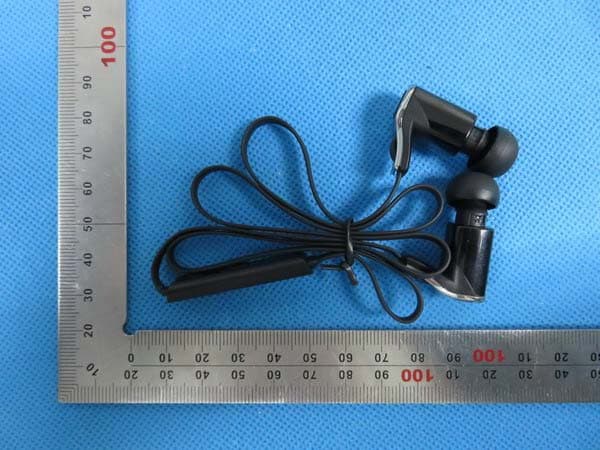
WTDG10
Oct 05, 2015Sporty Stereo Bluetooth Headset
Equipment Class
DXX - Part 15 Low Power Communication Device Transmitter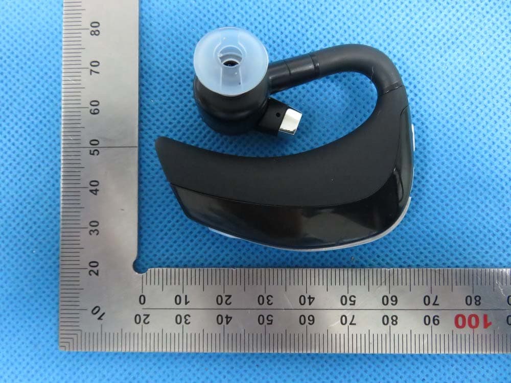
WTDM3
Oct 05, 2015Mono Bluetooth Headset
Equipment Class
DXX - Part 15 Low Power Communication Device Transmitter