WU8NB24G20V024 GHz NB automotive radar
Magna Electronics, LLC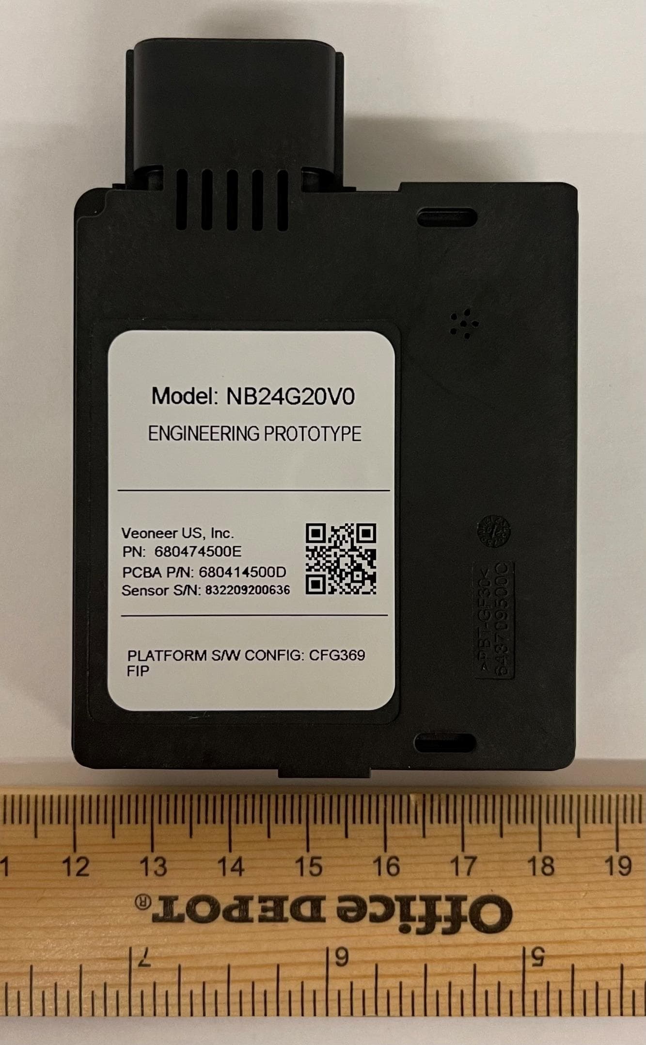
Click to zoom
Application Details
- Equipment Class
- DXX - Part 15 Low Power Communication Device Transmitter
- Date of Grant
- May 18, 2021
- Application Purpose
- Original Equipment
- Date of Application
- May 18, 2021
- Equipment Note
- 24 GHz NB automotive radar
- Frequency Range
- 24074.00000000 - 24230.00000000
- Company
- Magna Electronics, LLC
- Country
- United States
Documents & Files
Document Text
Text extracted from the exhibit documents filed with the FCC. Open a document above to read the original.
Users Manual
User Manual for Product Model: NB24G20V0 PUBLIC 24 GHz NB Radar Sensor User Manual Product Model: NB24G20V0 Veoneer US, Inc. 26360 American Drive Southfield, Michigan 48034 USA Phone: +1 248 223 0600 Fax: +1 248 223 8833 User Manual for Product Model: NB24G20V0 Page 2 of 7 PUBLIC Table of Contents 1 ABBREVIATIONS 3 1.1 LIST OF TERMINOLOGY AND ACRONYMS 3 2 PRODUCT OVERVIEW 3 2.1 PRODUCT DESCRIPTION 3 2.2 PRODUCT APPLICATION EXAMPLES 3 3 TYPICAL INSTALLATION 4 4 HARDWARE DESCRIPTION 4 5 SENSOR GENERIC SPECIFICATIONS 5 6 SENSOR FEATURES 5 7 CONFORMANCE STATEMENTS 6 7.1 USA 6 7.2 CANADA 6 7.3 RADIO FREQUENCY EXPOSURE INFORMATION 6 7.4 EUROPE 6 8 REVISION HISTORY 7 Table of Figures FIGURE 1: TYPICAL INSTALLATION POSITIONS ........................................................................................................................................... 4 FIGURE 2: GENERIC SENSOR ................................................................................................................................................................. 4 List of Tables TABLE 1: SENSOR SPECIFICATIONS ......................................................................................................................................................... 5 TABLE 2: REVISION HISTORY ................................................................................................................................................................. 7 User Manual for Product Model: NB24G20V0 Page 3 of 7 PUBLIC 1 Abbreviations 1.1 List of Terminology and Acronyms BSD Blind Spot Detection CAN Controller Area Network DSP Digital Signal Processor EMC ElectroMagnetic Compliance (regulatory standards) FM Frequency Modulation GHZ Giga-Hertz (10^9) HP Host Processor LCA Lane Change Assist MMIC Monolithic Microwave Integrated Circuit MCU MicroController Unit NB Narrow Band PCB Printed Circuit Board RADAR RAdio Detection and Ranging RCTA Rear Cross Traffic Alert RF Radio Frequency (or Microwave) 2 Product Overview 2.1 Product Description The products described here are part of a family of radars offered by Veoneer. They are intended for automotive use, operating in the 24.050 - 24.250GHz band. The radars are integrated into a vehicle to enhance vehicle safety systems. They can be integrated as a standalone sensor or sensors, or as part of more complex system that also may include cameras, lidar, and other type of sensors to provide features like Automatic Cruise Control, Automatic Emergency Break, Free Space Detections and other Autonomous Driving functions. 2.2 Product Application Examples The product can be used, but is not limited to the following applications: • Blind Spot Detection • Rear Cross Traffic • Lane change warning • Rear collision prevention systems • Automatic lane change systems • Pedestrian and Bicycle collision prevention User Manual for Product Model: NB24G20V0 Page 4 of 7 PUBLIC 3 Typical Installation The radar is typically installed in the positions of the vehicle depicted in Figure 1 often mounted behind a bumper or emblem. Figure 1: Typical Installation Positions 4 Hardware Description The NB RADAR is a fully integrated 24GHz radar sensor with both RF and DSP modules on the same PCB. The design supports a combination of pulsed Doppler and chirped FM waveforms that can detect moving or stationary vehicles in a high clutter environment. The sensor’s DSP – a multicore processor - controls all signal processing, diagnostics and communications. The RF module generates, transmits, receives and demodulates radar signals using two Veoneer MMICs. Software algorithms calculate target parameters such as range, speed and angle and this information is sent out to the vehicle over the CAN bus. The components are assembled into a plastic housing that is laser welded together. The sensor has no serviceable parts and can’t be opened without permanent damage. Figure 2: Generic Sensor User Manual for Product Model: NB24G20V0 Page 5 of 7 PUBLIC 5 Sensor Generic Specifications Sensor Specifications & Functions Value Unit Operating Conditions Frequency Band 24.050 – 24.250 (ISM) GHz Vehicle Network Interface CAN 2.0B - Operating Temperature -40C to +85 C (External Ambient) Input Operating Voltage 8.0-16.0 VDC RF Output Power (EIRP) 13.26 dBm Operating Life 15 yrs. Waveform Parameters Cycle Time 81.62 ms Bandwidth <200 MHz Physical Parameters Size 72 x 63 x 16 mm (excluding connector) Weight <75 g Vehicle Physical Interface Standard is 6 Pin DUAL CAN - Table 1: Sensor Specifications 6 Sensor Features The BSD algorithm detects and reports “Objects of Interest" on either side of the vehicle, within a specified “blind spot” zone. The feature generates a signal which is used to drive a visual display placed in the outside view mirror to alert the driver to the presence of objects of interest within the defined SBZA zone. The LCA algorithm detects and reports to the driver that a vehicle is rapidly approaching the host vehicle in one of the adjacent lanes. The feature generates a signal which is used to drive a visual display placed in the outside view mirror and/or request a chime or vibrating seat cushion, to alert the driver to the approach of objects of interest within the defined LCA zone. The RCTA algorithm detects and reports “Objects of Interest” behind the host vehicle, within a specified RCTA coverage zone. The feature generates a signal which is used to drive a visual display to alert the driver of the presence of objects of interest that may cause a collision with the host vehicle within the defined RCTA zone. User Manual for Product Model: NB24G20V0 Page 6 of 7 PUBLIC 7 Conformance Statements 7.1 USA This device complies with Part 15 of the FCC Rules. Operation is subject to the following two conditions: (1) this device may not cause harmful interference, and (2) this device must accept any interference received, including interference that may cause undesired operation. CAUTION TO USERS Changes or modifications n…
Text truncated - open the document above for the full version.
Attestation Statements
Veoneer US, Inc. 26360 American Drive Southfield, Michigan 48034 USA Phone: +1-248-223-0600 Fax: +1-248-223-8833 www.veoneer.com Confidentiality Request Letter For Certification Service in the USA Federal Communication Commission Equipment Authorization Division, Application Processing Branch 7435 Oakland Mills Road Columbia, MD 21048 To whom it may concern Pursuant to Paragraphs §0.457 and 0.459 of the Commission’s Rules (47 C.F.R.) and Section §552(b)(4) of the Freedom of Information Act, we request confidentiality for the documentation of the following products: FCC ID Model name WU8NB24G20V0 NB24G20V0 For the products listed above, we request permanent confidentiality for all applicable exhibits as there are: • the Operational Description • the Block Diagram • the Schematics • the Parts Lists • the Tune Up Information The above listed exhibits contain trade secrets and proprietary information that could be of benefit to our competitors. If you have any questions, please feel free to contact us at the address shown below. Sincerely, Signature Date Printed Name Jeff Coote Company Veoneer US, Inc. Address 26360 American Drive Southfield, MI 48034 USA Phone +1 248 223 0600 Email [email protected] 2021-03-31
Attestation Statements
Veoneer US, Inc. 26360 American Drive Southfield, Michigan 48034 USA Phone: +1-248-223-0600 Fax: +1-248-223-8833 www.veoneer.com Short Term Confidentiality Request Letter For Certification Service in the USA Federal Communication Commission Equipment Authorization Division, Application Processing Branch 7435 Oakland Mills Road Columbia, MD 21048 To whom it may concern Pursuant to Paragraphs §0.457 and 0.459 of the Commission’s Rules (47 C.F.R.) and in accordance with the FCC Public notice dated June 15, 2004 (DA 04-1705), we request short term confidentiality prior to marketing the device for the documentation of the following products: FCC ID Model name WU8NB24G20V0 NB24G20V0 For the products listed above, we request short term confidentiality for all applicable exhibits as there are: • External photos • Internal photos • Test setup photos • User manual The above listed exhibits contain business sensitive information which we wish to keep confidential until the actual marketing of our device, that is planned for: Short term confidentiality release date: August 30, 2021 If you have any questions, please feel free to contact us at the address shown below. Sincerely, Signature Date Printed Name Jeff Coote Company Veoneer US, Inc. Address 26360 American Drive Southfield, MI 48034 USA Phone +1 248 223 0600 Email [email protected] 2021-03-31
External Photos
Product Model Photos: NB24G20V0_EXTERNAL 1 (7) CONFIDENTIAL 24 GHz Radar Sensor External Photos Product Model: NB24G20V0 Product Model Photos: NB24G20V0_EXTERNAL 2 (7) CONFIDENTIAL Product Model Photos: NB24G20V0_EXTERNAL 3 (7) CONFIDENTIAL Product Model Photos: NB24G20V0_EXTERNAL 4 (7) CONFIDENTIAL Product Model Photos: NB24G20V0_EXTERNAL 5 (7) CONFIDENTIAL Product Model Photos: NB24G20V0_EXTERNAL 6 (7) CONFIDENTIAL Product Model Photos: NB24G20V0_EXTERNAL 7 (7) CONFIDENTIAL
External Photos
Germany · IBL-Lab GmbH · Heinrich-Hertz-Allee 7-10 · 66386 Sankt Ingbert · Tel: +49 6894 38938-0 · Fax: +49 6894 38938-99 1 / 6 Company Register: 105151, Amtsgericht Saarbrücken URL: www.ib-lenhardt.de · E-Mail: [email protected] Annex A External photographs of EUT part of / in addition to Test report no.: 20054147-18456 Tested by (name, function, signature) Karsten Geraldy Head of Laboratory RF signature Approved by (name, function, signature) Dr.-Ing. Harald Ansorge Managing Director signature Annex A of TR no.: 20054147-18456 2 / 6 IBL-Lab GmbH Photo No. 1 Photo No. 2 Annex A of TR no.: 20054147-18456 3 / 6 IBL-Lab GmbH Photo No. 3 Photo No. 4 Annex A of TR no.: 20054147-18456 4 / 6 IBL-Lab GmbH Photo No. 5 Photo No. 6 Annex A of TR no.: 20054147-18456 5 / 6 IBL-Lab GmbH Photo No. 7 Photo No. 8 Annex A of TR no.: 20054147-18456 6 / 6 IBL-Lab GmbH Revision History -1 Initial Version End of Annex
ID Label/Location Info
Veoneer US, Inc. 26360 American Drive Southfield, Michigan 48034 USA Phone: +1-248-223-0600 Fax: +1-248-223-8833 www.veoneer.com Compliance Label Information Product Name: NB24G20V0 Label 1 Label 2 2(2) Label Location
Internal Photos
Product Model Photos: NB24G20V0_INTERNAL 1 (6) CONFIDENTIAL 24 GHz Radar Sensor Internal Photos Product Model: NB24G20V0 Product Model Photos: NB24G20V0_INTERNAL 2 (6) CONFIDENTIAL Product Model Photos: NB24G20V0_INTERNAL 3 (6) CONFIDENTIAL Product Model Photos: NB24G20V0_INTERNAL 4 (6) CONFIDENTIAL Product Model Photos: NB24G20V0_INTERNAL 5 (6) CONFIDENTIAL Product Model Photos: NB24G20V0_INTERNAL 6 (6) CONFIDENTIAL
Internal Photos
Germany · IBL-Lab GmbH · Heinrich-Hertz-Allee 7-10 · 66386 Sankt Ingbert · Tel: +49 6894 38938-0 · Fax: +49 6894 38938-99 1 / 4 Company Register: 105151, Amtsgericht Saarbrücken URL: www.ib-lenhardt.de · E-Mail: [email protected] Annex B Internal photographs of EUT (as provided by applicant) part of / in addition to Test report no.: 20054147-18456 Tested by (name, function, signature) Karsten Geraldy Head of Laboratory RF signature Approved by (name, function, signature) Dr.-Ing. Harald Ansorge Managing Director signature Annex B of TR no.: 20054147-18456 2 / 4 IBL-Lab GmbH Photo No. 1 Photo No. 2 Annex B of TR no.: 20054147-18456 3 / 4 IBL-Lab GmbH Photo No. 3 Photo No. 4 Annex B of TR no.: 20054147-18456 4 / 4 IBL-Lab GmbH Revision History -1 Initial Version End of Annex
Test Report
Germany · IBL-Lab GmbH · Heinrich-Hertz-Allee 7-10 · 66386 Sankt Ingbert · Tel: +49 6894 38938-0 · Fax: +49 6894 38938-99 1 / 47 Company Register: 105151, Amtsgericht Saarbrücken URL: www.ib-lenhardt.de · E-Mail: [email protected] Test Report Test report no.: 20054147-18456-1 Date of issue: 2021-03-12 Test result: The test item - passed - and complies with below listed standards. Applicant Veoneer US, Inc. Manufacturer Veoneer US, Inc. Test Item NB24G20V0 RF-Spectrum Testing according to: FCC 47 CFR Part 15 Radio Frequency Devices, Subpart C - §15.249 Operation within the bands 902-928 MHz, 2400-2483.5 MHz, 5725-5875 MHZ, and 24.0-24.25 GHz Tested by (name, function, signature) Karsten Geraldy Head of Laboratory RF signature Approved by (name, function, signature) Dr.-Ing. Harald Ansorge Managing Director signature TR no.: 20054147-18456-1 2021-03-12 2 / 47 IBL-Lab GmbH Applicant and Test item details Applicant Veoneer US, Inc. 26360 American Drive Southfield, MI 48034, USA Manufacturer Veoneer US, Inc. 26360 American Drive Southfield, MI 48034, USA Test item description 24 GHz NB automotive radar Model/Type reference NB24G20V0 FCC ID WU8NB24G20V0 Frequency 24.05 GHz ± 24.25 GHz Antenna Integrated planar patch antenna Power supply 8.0 V ± 16.0 V DC Temperature range -40 °C ± +85 °C Disclaimer and Notes The content of this rest report relates to the mentioned test sample(s) only. Without a written permit of IBL-Lab GmbH, this test report shall not be reproduced, except in full. Copyright : All rights reserved by IBL-Lab GmbH Within this test report, a ☒ point / ☐ comma is used as a decimal separator. If otherwise, a detailed note is added adjected to its use. Decision rule: Binary Statement for Simple Acceptance Rule according ILAC-G8:09/2019 IBL-Lab GmbH does not take test samples. The EUT used for testing is provided by the applicant. TR no.: 20054147-18456-1 2021-03-12 3 / 47 IBL-Lab GmbH 1 TABLE OF CONTENTS 1 TABLE OF CONTENTS ......................................................................................................................... 3 2 GENERAL INFORMATION ................................................................................................................... 4 2.1 Administrative details .......................................................................................................................... 4 2.2 Possible test case verdicts ................................................................................................................. 4 2.3 Observations ....................................................................................................................................... 4 2.4 Opinions and interpretations ............................................................................................................... 4 2.5 Revision History .................................................................................................................................. 4 2.6 Further documents .............................................................................................................................. 5 3 ENVIRONMENTAL & TEST CONDITIONS........................................................................................... 6 3.1 Environmental conditions ................................................................................................................... 6 3.2 Normal and extreme test conditions ................................................................................................... 6 4 TEST STANDARDS AND REFERENCES ............................................................................................ 6 5 EQUIPMENT UNDER TEST (EUT) ....................................................................................................... 7 5.1 Product description ............................................................................................................................. 7 5.2 Description of test item ....................................................................................................................... 7 5.3 Technical data of test item .................................................................................................................. 7 5.4 Additional information ......................................................................................................................... 7 6 Test Setup Description........................................................................................................................... 8 6.1 Semi Anechoic Chamber with Ground Plane ..................................................................................... 9 6.2 Fully Anechoic Chamber .................................................................................................................. 11 6.3 Radiated measurements > 18 GHz .................................................................................................. 12 6.4 Radiated measurements > 50 GHz .................................................................................................. 12 7 Measurement procedures .................................................................................................................... 14 7.1 Radiated spurious emissions from 9 kHz to 30 MHz ........................................................................ 14 7.2 Radiated spurious emissions from 30 MHz to 1 GHz ....................................................................... 15 7.3 Radiated spurious emissions from 1 GHz to 18 GHz ....................................................................... 16 7.4 Radiated spurious emissions above 18 GHz ................................................................................... 17 8 SUMMARY OF TEST RESULTS ......................................................................................................... 18 9 TEST RESULTS .....................................................................…
Text truncated - open the document above for the full version.
Test Setup Photos
Germany · IBL-Lab GmbH · Heinrich-Hertz-Allee 7-10 · 66386 Sankt Ingbert · Tel: +49 6894 38938-0 · Fax: +49 6894 38938-99 1 / 8 Company Register: 105151, Amtsgericht Saarbrücken URL: www.ib-lenhardt.de · E-Mail: [email protected] Annex C Photographs of test setup for FCC part of / in addition to Test report no.: 20054147-18456 Tested by (name, function, signature) Karsten Geraldy Head of Laboratory RF signature Approved by (name, function, signature) Dr.-Ing. Harald Ansorge Managing Director signature Annex C of TR no.: 20054147-18456 2 / 8 IBL-Lab GmbH Photo No. 1 Photo No. 2 Annex C of TR no.: 20054147-18456 3 / 8 IBL-Lab GmbH Photo No. 3 Annex C of TR no.: 20054147-18456 4 / 8 IBL-Lab GmbH Photo No. 4 Annex C of TR no.: 20054147-18456 5 / 8 IBL-Lab GmbH Photo No. 5 Photo No. 6 Annex C of TR no.: 20054147-18456 6 / 8 IBL-Lab GmbH Photo No. 7 Photo No. 8 Annex C of TR no.: 20054147-18456 7 / 8 IBL-Lab GmbH Photo No. 9 Annex C of TR no.: 20054147-18456 8 / 8 IBL-Lab GmbH Revision History -1 Initial Version End of Annex
Contact Information
Applicant
Kim Mooney(Director, Radar Platforms)
Test Firm
IBL-Lab GmbHKarsten Geraldy
[email protected]+ 49 6894 389 3868
Technical Specifications
| # | Rule Parts | Frequency Range | Power Output |
|---|---|---|---|
| 1 | 15C | 24.07 GHz - 24.23 GHz | - |
Other Applications from Magna Electronics, LLC
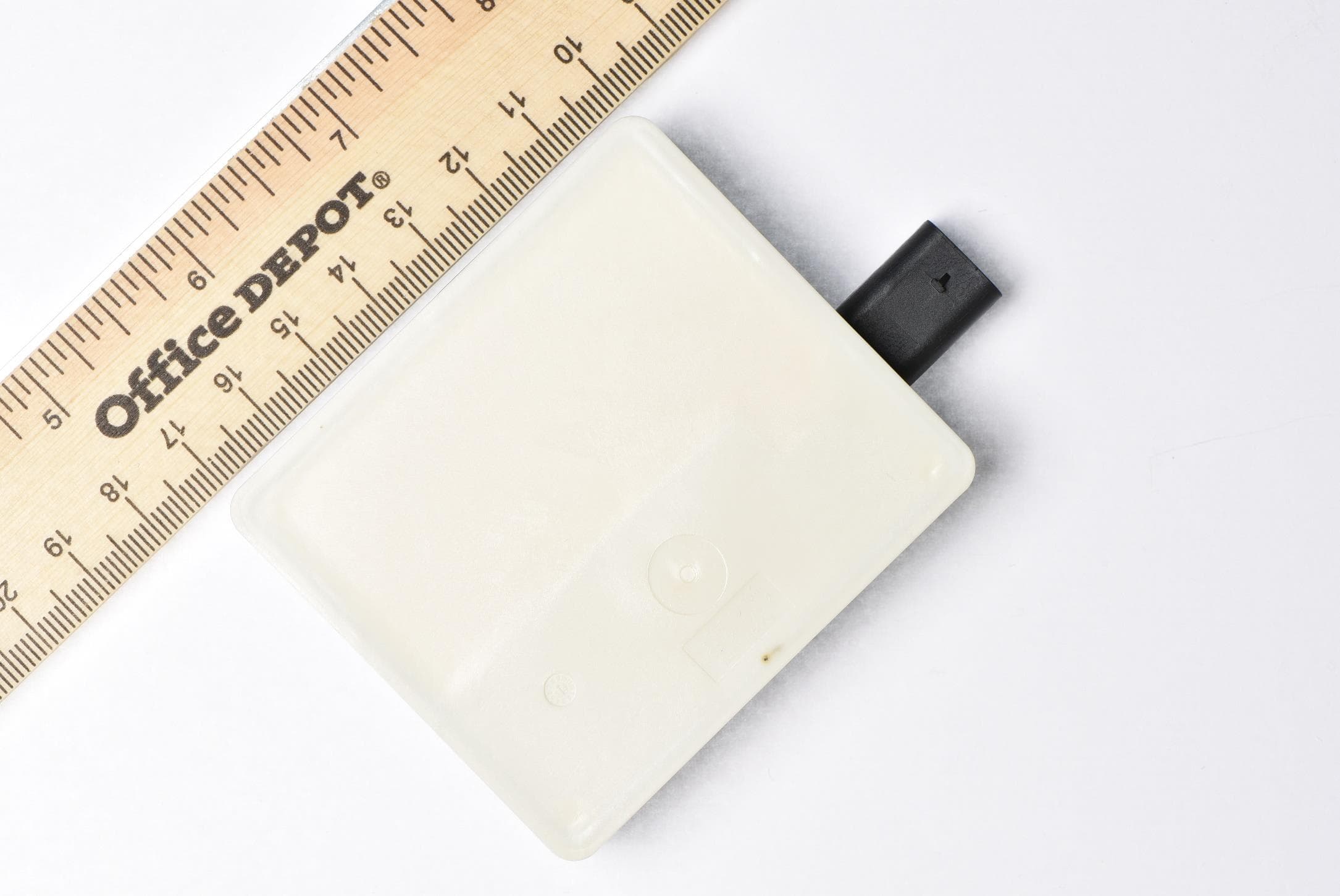
WU877V125CRN
Apr 28, 202177 GHz CRN Radar Sensor
Equipment Class
VRD - Part 95 Vehicular Radar Systems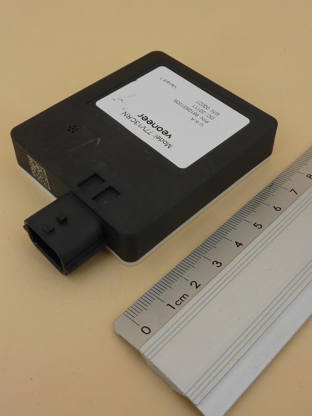
WU877V13CRN
Aug 24, 2020CRN Radar Sensor
Equipment Class
VRD - Part 95 Vehicular Radar Systems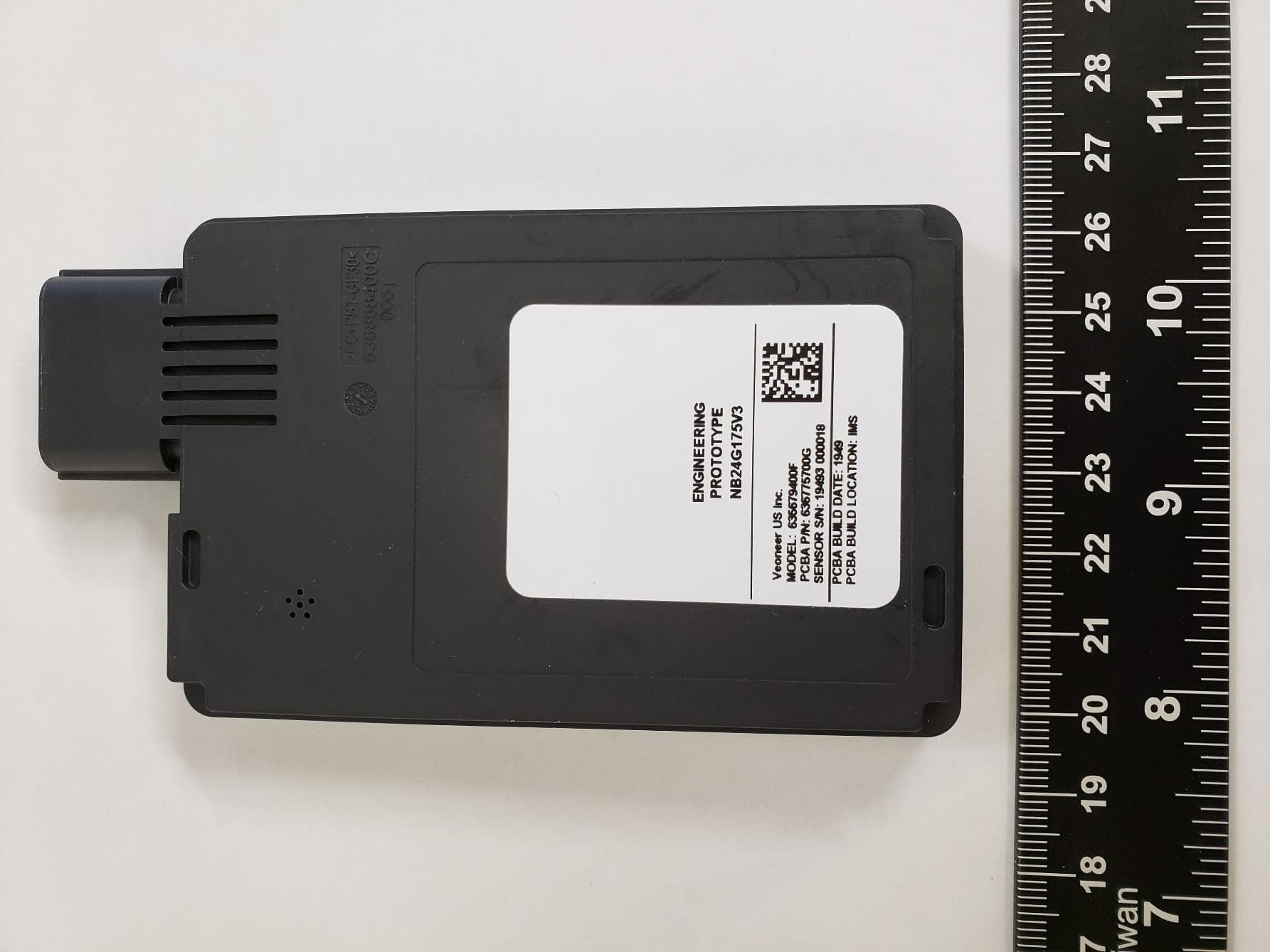
WU8NB24G175V3
May 28, 202024 GHz SRS Radar Sensor
Equipment Class
DXX - Part 15 Low Power Communication Device Transmitter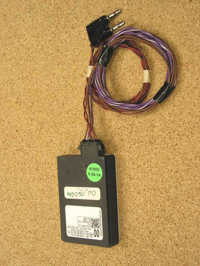
WU877MMRV1
May 25, 2015Vehicle Radar
Equipment Class
FDS - Part 15 Field Disturbance Sensor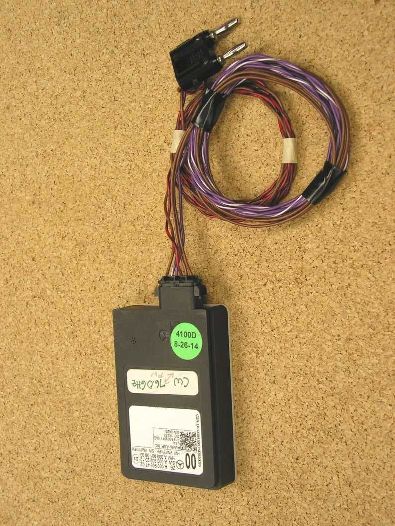
WU877MMR
Nov 20, 2014Vehicle Radar
Equipment Class
FDS - Part 15 Field Disturbance Sensor