WUO-WTX1011AUDIO FREQUENCY WIRELESS TRANSCEIVER
Sonavox Canada Inc.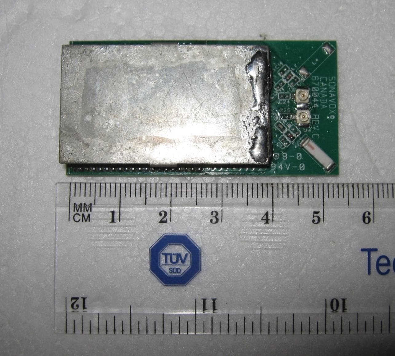
Click to zoom
Application Details
- Equipment Class
- DTS - Digital Transmission System
- Date of Grant
- Jan 20, 2011
- Application Purpose
- Original Equipment
- Date of Application
- Jan 09, 2011
- Equipment Note
- AUDIO FREQUENCY WIRELESS TRANSCEIVER
- Frequency Range
- 2403.00000000 - 2478.00000000
- Company
- Sonavox Canada Inc.
- Country
- Canada
Documents & Files
Document Text
Text extracted from the exhibit documents filed with the FCC. Open a document above to read the original.
Users Manual
Sonavox Canada Inc. 10 Konrad Crescent, Markham, Ontario, L3R 8T7, Canada. Telephone: 9055139850 Facsimile: 9054740592 Regulatory Compliance: This device complies with Part 15 of the FCC Rules. Operation is subject to the following two conditions: (1) this device may not cause harmful interference, and (2) this device must accept any interference received, including interference that may cause undesired operation. Any changes or modifications of this product, not approved by manufacturer will void the user’s authority to operate the equipment.
Users Manual
SONAVOX Inc. Wireless Audio Transceiver Module – WTX1011/WRX1011Users Manual 1 This document is designed to provide general information for use of the Audio Wireless Transceiver Module WTX1010/WRX1011. EMI/EMC Compliance Guidelines FCC Compliance This device complies with Part 15 of the FCC Rules. Operation is subject to the following two conditions: (1) This device may not cause harmful interference, and (2) This device must accept any interference received, including interference that may cause undesired operation. Changes or modifications not expressly approved by the party responsible for compliance could void the user’s authority to operate the equipment. IC Compliance This Class B digital apparatus complies with Canadian RSS-210. When integrating the WTX1010/WRX1011 module into your own product, you must: 1. Use only the provided chip antenna. 2. Operate the module according to the specifications listed in this data sheet. 3. Include a label clearly visible on the exterior of the product which states: “Contains FCC ID: WUO-WTX1010/WRX1011 / IC: 7985A-WTX1010/WRX1011”. 4. It is mandatory that you consult all FCC and IC documentation for use of a modular approved product, and comply with all listed guidelines and additional testing that may be required. Specifications WTX1010/WRX1011 functional block diagrams SPI TWI EEPROM GPIO SPI I2S KLR3012 I2S 22.576649MHZ ANT SWITCH DIVERSITY NETWORK MATCHING NETWORK MATCHING ANTENNA 2.4GHZ GPIO Figure 1 RF Performance: Outdoor range (LOS) 15m. Maximum Transmitting RF Power - 0 dBm. Frequency ISM 2.400 - 2.480 GHz. SONAVOX Inc. Wireless Audio Transceiver Module – WTX1011/WRX1011Users Manual 2 Physical Dimensions Electrical Parameters Absolute maximum Supply Voltage Range 2.0 - 3.3 VDC Nominal Supply voltage – 2.1VDC Current Requirements – 10-15mA Operating Temperature Range - 0 to 70 °C / 32 to 158 °F PCB Material and layout considerations The PCB material for the base PCB should be FR4 glass epoxy. All supply pins should have decoupling electrolytic capacitors and ferrite beads positioned as close to the supply pins as possible. No components or traces should be located close to the antenna. Recommended minimum distance is 10mm. Firmware Sonavox provides the firmware on the module for our customers. Other features The module is RoHS compliant. The module is FCC approved (documentation available on request). The module is IC approved (documentation available on request). SONAVOX Inc. Wireless Audio Transceiver Module – WTX1011/WRX1011Users Manual 3 Module Pin-out Pin Number Pin Name Pin Description CONNECTOR J1 1 GND DIGITAL GROUND 2 GND DIGITAL GROUND 3 GND DIGITAL GROUND 4 GND DIGITAL GROUND 5 GND DIGITAL GROUND 6 GND DIGITAL GROUND 7 GND DIGITAL GROUND 8 TEST CONNECT TO GROUND 9 SS0 SPI INTERFACE SLAVE SELECT 0 10 GND DIGITAL GROUND 11 AUDIO_DETECT AUDIO SIGNAL DETECT FOR ADC 12 IO_15 GPIO 13 GND DIGITAL GROUND 14 IO-16 IO_16 15 IO_17 IO_17 16 GND DIGITAL GROUND 17 TWI_CLK I2C CLOCK 18 TWI_DAT I2C DATA 19 GND DIGITAL GROUND 20 5V POWER SUPPLY 5V CONNECTOR J2 1 GND DIGITAL GROUND 2 RESET_N ACTIVE LOW RESET 3 RES2 UART0 RX 4 RES1 UART0 TX 5 MCLK MASTER AUDIO CLOCK 6 DAI_BCLK DIGITAL AUDIO INTERFACE BIT CLOCK 7 DAI_FS DIGITAL AUDIO INTERFACE FRAME SYNC 8 DAI_DATA DIGITAL AUDIO INTERFACE DATA 9 UART1_OUT UART1 OUTPUT 10 UART1_IN UART1 INPUT 11 GND DIGITAL GROUND 12 SS2 GPIO 9 13 ASSOC GPIO 10 14 MOSI SPI MASTER OUT/SLAVE IN 15 DIV_CTL_MISO ANTENNA DIV CONTROL/SPI MASTER IN / SLAVE OUT 16 IO_8 GPIO 8 17 SCLK SPI CLOCK 18 GND DIGITAL GROUND 19 GND DIGITAL GROUND 20 GND DIGITAL GROUND
External Photos
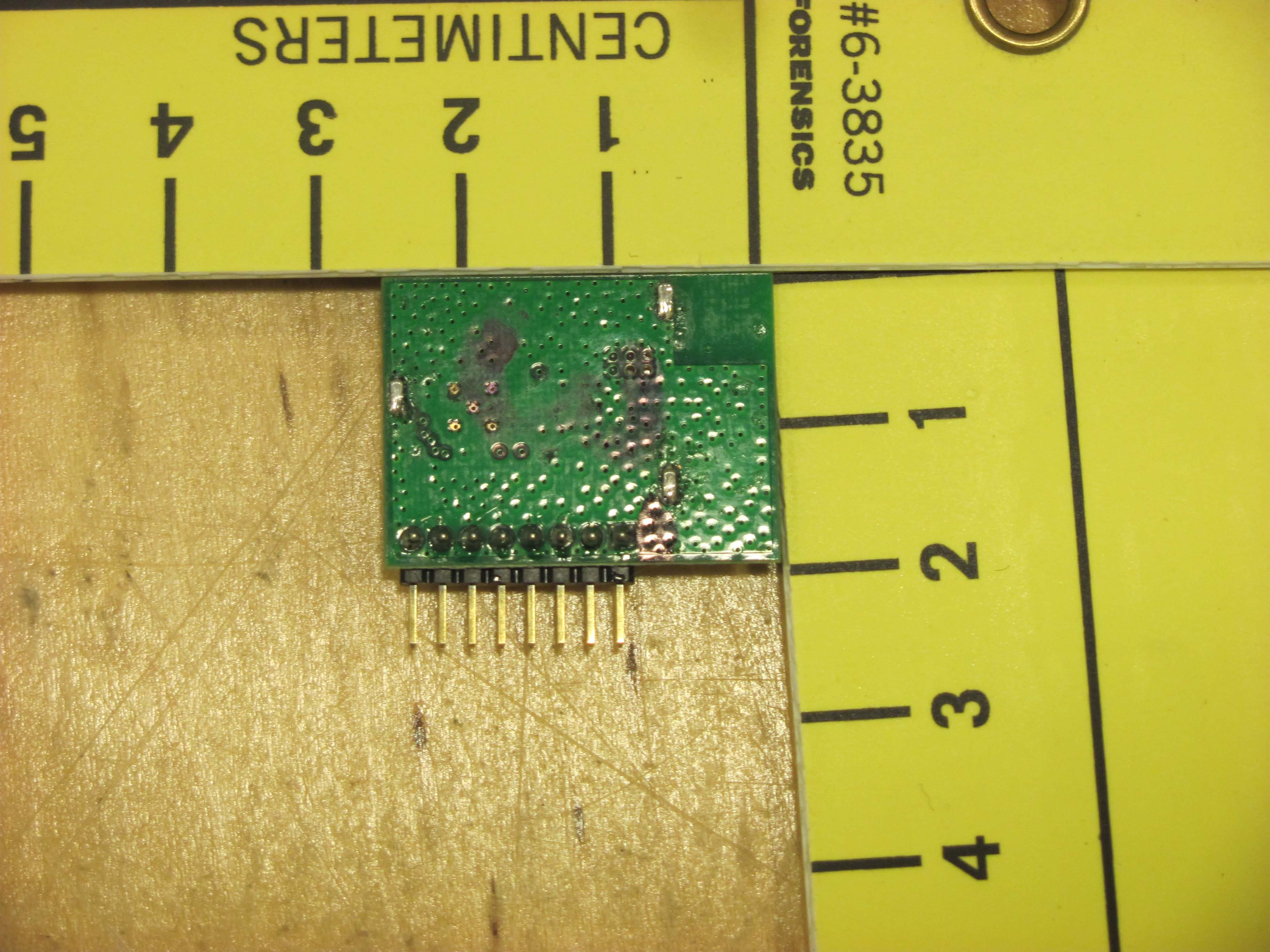
EUT – Top view EUT – Bottom view
ID Label/Location Info
Filename: Bird RF RX Module Label Rev A.cdr 1 Color: Black on White Background Material: 4 mil white vinyl, adhesive on rear Silkscreen P/N: LA0167 Revision: A Model: WTX1011 FCC I.D. WUO-WTX1011 I.C. 7985A-WTX1011 WRX1011
ID Label/Location Info
Filename: RF TX Module Label Rev A.cdr 1 Color: Black on White Background Material: 4 mil white vinyl, adhesive on rear Silkscreen P/N: LA0168 Revision: A Model: WTX1011 FCC I.D. WUO-WTX1011 I.C. 7985A-WTX1011 WTX1011
Internal Photos
EUT – Top view (shield removed) EUT – Bottom view
Operational Description
SONAVOX Inc. Wireless Audio Transceiver Module – WTX1011/WRX1011 Operations 1 Overview The WTX1010/WRX1011 Wireless Audio Module is the ideal solution for customers ready to make their audio products wireless. Whether you’re in the development stage or ready to mass manufacture, the WTX1010/WRX1011 will provide the reliable, standards-compliant, guaranteed performance you need. Product Highlights RF Performance Optimized and Guaranteed WTX1010/WRX1011 modules are thoroughly optimized and tested to ensure consistent and superior RF performance. Small Form Factor The WTX1010/WRX1011 minimal size makes it easy to integrate into existing enclosures. Electrical Characteristics Outdoor range (LOS) 15m. Transmitting Power - 0 dBm. Frequency ISM 2.400 - 2.480 GHz. Power requirements Supply Voltage Range 2.0 - 3.3 VDC Nominal Supply voltage – 2.1VDC Current Consumption – 15mA Physical Specifications Operating Temperature 0 to 70 °C / 32 to 158 °F FCC Compliance This device complies with Part 15 of the FCC Rules. Operation is subject to the following two conditions (1) This device may not cause harmful interference, and (2) This device must accept any interference received, including interference that may cause undesired operation. Changes or modifications not expressly approved by the party responsible for compliance could void the user’s authority to operate the equipment. IC Compliance This Class B digital apparatus complies with Canadian ICES-003. Cet appareil numérique de la classe A est conforme à la norme NMB-003 du Canada. When integrating the WTX1010/WRX1011 module into your own product, you must: Use only the provided chip antenna. Operate the module according to the specifications listed in this data sheet. Include a label clearly visible on the exterior of the product which states: “Contains FCC ID: WUO- WTX1010/WRX1011 / IC: 7985A-WTX1010/WRX1011”. It is mandatory that you consult all FCC and IC documentation for use of a modular approved product, and comply with all listed guidelines and additional testing that may be required. SONAVOX Inc. Wireless Audio Transceiver Module – WTX1011/WRX1011 Operations 2 Module Connection specifications Pin description: Pin Number Pin Name Pin Description CONNECTOR J1 1 GND DIGITAL GROUND 2 GND DIGITAL GROUND 3 GND DIGITAL GROUND 4 GND DIGITAL GROUND 5 GND DIGITAL GROUND 6 GND DIGITAL GROUND 7 GND DIGITAL GROUND 8 TEST CONNECT TO GROUND 9 SS0 SPI INTERFACE SLAVE SELECT 0 10 GND DIGITAL GROUND 11 AUDIO_DETECT AUDIO SIGNAL DETECT FOR ADC 12 IO_15 GPIO 13 GND DIGITAL GROUND 14 IO-16 IO_16 15 IO_17 IO_17 16 GND DIGITAL GROUND 17 TWI_CLK I2C CLOCK 18 TWI_DAT I2C DATA 19 GND DIGITAL GROUND 20 5V POWER SUPPLY 5V CONNECTOR J2 1 GND DIGITAL GROUND 2 RESET_N ACTIVE LOW RESET 3 RES2 UART0 RX 4 RES1 UART0 TX 5 MCLK MASTER AUDIO CLOCK 6 DAI_BCLK DIGITAL AUDIO INTERFACE BIT CLOCK 7 DAI_FS DIGITAL AUDIO INTERFACE FRAME SYNC 8 DAI_DATA DIGITAL AUDIO INTERFACE DATA 9 UART1_OUT UART1 OUTPUT 10 UART1_IN UART1 INPUT 11 GND DIGITAL GROUND 12 SS2 GPIO 9 13 ASSOC GPIO 10 14 MOSI SPI MASTER OUT/SLAVE IN 15 DIV_CTL_MISO ANTENNA DIV CONTROL/SPI MASTER IN / SLAVE OUT 16 IO_8 GPIO 8 17 SCLK SPI CLOCK 18 GND DIGITAL GROUND 19 GND DIGITAL GROUND 20 GND DIGITAL GROUND SONAVOX Inc. Wireless Audio Transceiver Module – WTX1011/WRX1011 Operations 3 Module Dimensions:
RF Exposure Info
Global EMC Prediction of MPE limit at a given distance Equation from page 18 of OET Bulletin 65, Edition 97-01 where:S = power density P = power input to the antenna G = power gain of the antenna in the direction of interest relative to an isotropic radiator R = distance to the center of radiation of the antenna Maximum peak output power at antenna input terminal:5.00(dBm) Maximum peak output power at antenna input terminal:3.16227766(mW) Antenna gain(typical):0(dBi) Maximum antenna gain:1(numeric) Time Averaging:100(%) Prediction distance:1(cm) Prediction frequency:2480(MHz) MPE limit for uncontrolled exposure at prediction frequency:1(mW/cm^2) Power density at prediction frequency:0.251646(mW/cm^2) Margin of compliance:-6.0(dB) This equates to2.516460605W/m^2PASS For informationThis equates to30.8010657V/m Note: This device does not exceed the 60 / f (GHz) in mW limit as per FCC KDB 447498 2(a)(i), so it is allowable to be used in portable exposure conditions with no restrictions on host platforms 2 4R PG S G = power gain of the antenna in the direction of interest relative to an isotropic radiator
Test Report
LAB REGISTRATION #6844A-1 FCC REGISTRATION #612361 Testing Laboratory Certificate #2555.01 Page 1 of 67 Report issue date: 1/6/20110 GEMC File #: GEMC-FCC-19994R1 © Global EMC Inc. This test report shall not be reproduced except in full, without written approval of Global EMC Inc. This report is based on GEMC Template “FCC 15 247 Rev2.” Global EMC Inc. Labs EMC & RF Test Report As per RSS 210 Issue 7:2007 & FCC Part 15 Subpart C:2010 Unlicensed Intentional Radiators on the Wireless Audio Transceiver Module – WTX1011 Raymond Lee Au Project Engineer Global EMC Inc. 180 Brodie Drive, Unit 2 Richmond Hill, ON, L4B 3K8 Canada Ph: (905) 883-8189 Testing produced for See Appendix A for full customer & EUT details. Client Sonavox Audio Solution Product Wireless Audio Transceiver Module – WTX1011 Standard(s) RSS 210 Issue 7:2007 / FCC Part 15 Subpart C 15:2010 Page 2 of 67 Report issue date: 1/6/20110 GEMC File #: GEMC-19994R1 © Global EMC Inc. This test report shall not be reproduced except in full, without written approval of Global EMC Inc. Table of Contents Table of Contents ................................................................................................................... 2 Report Scope .......................................................................................................................... 3 Summary ................................................................................................................................ 4 Test Results Summary ....................................................................................................... 5 Justifications, Descriptions, or Deviations......................................................................... 6 Applicable Standards, Specifications and Methods ........................................................... 7 Sample calculation(s) ......................................................................................................... 8 Document Revision Status ................................................................................................. 8 Definitions and Acronyms ..................................................................................................... 9 Testing Facility .................................................................................................................... 10 Calibrations and Accreditations ....................................................................................... 10 Testing Environmental Conditions and Dates ................................................................. 11 Detailed Test Results Section .............................................................................................. 12 Power Line Conducted Emissions ................................................................................... 13 Radiated Emissions .......................................................................................................... 21 6dB Bandwidth of Digitally Modulated Systems ............................................................ 35 Maximum Peak Envelope Conducted Power .................................................................. 42 Spurious Conducted Emissions ....................................................................................... 48 Power Spectral Density .................................................................................................... 54 Maximum Permissible Exposure ..................................................................................... 57 Appendix A – EUT Summary .............................................................................................. 59 Appendix B – EUT and Test Setup Photographs................................................................. 60 Client Sonavox Audio Solution Product Wireless Audio Transceiver Module – WTX1011 Standard(s) RSS 210 Issue 7:2007 / FCC Part 15 Subpart C 15:2010 Page 3 of 67 Report issue date: 1/6/20110 GEMC File #: GEMC-19994R1 © Global EMC Inc. This test report shall not be reproduced except in full, without written approval of Global EMC Inc. Report Scope This report addresses the EMC verification testing and test results of the Wireless Audio Transceiver Module – WTX1011, herein referred to as EUT (Equipment Under Test) performed at Global EMC Labs. The EUT was tested for compliance against the following standards: RSS 210 Issue 7:2007 / FCC Part 15 Subpart C 15:2010 Test procedures, results, justifications, and engineering considerations, if any, follow later in this report. The results contained in this report relate only to the item(s) tested. This report does not imply product endorsement by A2LA or any other accreditation agency, any government, or Global EMC Inc. Opinions/interpretations expressed in this report, if any, are outside the scope of Global EMC Inc accreditation. Any opinions expressed do not necessarily reflect the opinions of Global EMC Inc, unless otherwise stated. Client Sonavox Audio Solution Product Wireless Audio Transceiver Module – WTX1011 Standard(s) RSS 210 Issue 7:2007 / FCC Part 15 Subpart C 15:2010 Page 4 of 67 Report issue date: 1/6/20110 GEMC File #: GEMC-19994R1 © Global EMC Inc. This test report shall not be reproduced except in full, without written approval of Global EMC Inc. Summary The results contained in this report relate only to the item(s) tested. EUT FCC Certification #, FCC ID: WUO-WTX1011 EUT Industry Canada Certification #, IC: 7985A-WTX1011 EUT Passed all tests performed. Yes (see test results summary) Tests conducted by Raymond Lee Au Client Sonavox Audio Solution Product Wireless Audio Transceiver Module – WTX1011 Standard(s) RSS 210 Issue 7:2007 / FCC Part 15 Subpart C 15:2010 Page 5 of 67 Report issue date: 1/6/20110 GEMC File #: GEMC-19994R1 © Global EMC Inc. This test report shall not be reproduced except in full, without written approval of Global EMC Inc. Test Results Summary Standard/Method Description Class/Limit Result FCC 1…
Text truncated - open the document above for the full version.
Test Setup Photos
Radiated Emissions – Setup Radiated Emissions 2 – Setup Radiated Emissions – Close Up (worst case EUT configuration) Antenna Conducted – Setup Power Line Conducted Emissions Setup
Contact Information
Applicant
Joe Riggi(President)
Test Firm
Global EMC Inc.Scott Drysdale
Technical Specifications
| # | Rule Parts | Frequency Range | Power Output |
|---|---|---|---|
| 1 | 15C | 2.40 GHz - 2.48 GHz | 3.00 mW |
Other Applications from Sonavox Canada Inc.
WUO-WBT1012
Jan 20, 2015BLE module for control application
Equipment Class
DTS - Digital Transmission System
WUO-WBT1010
Mar 12, 2013Bluetooth Audio Module
Equipment Class
DTS - Digital Transmission System
WUO-WTX1015
Apr 28, 2011AUDIO FREQUENCY WIRELESS TRANSMITTER
Equipment Class
DTS - Digital Transmission System
WUO-WTX1016
Apr 28, 2011AUDIO FREQUENCY WIRELESS TRANSMITTER
Equipment Class
DTS - Digital Transmission System
WUO-WTX1010
Oct 05, 2010AUDIO FREQUENCY WIRELESS TRANSCEIVER
Equipment Class
DTS - Digital Transmission System