WVB-AVVIO505GSM MOBILE PHONE-USB PORTION
Brightstar Corporation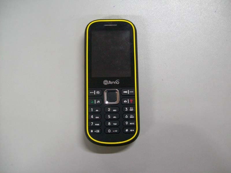
Click to zoom
Application Details
- Equipment Class
- JBP - Part 15 Class B Computing Device Peripheral
- Date of Grant
- Jan 13, 2010
- Application Purpose
- Original Equipment
- Date of Application
- Jan 11, 2010
- Equipment Note
- GSM MOBILE PHONE-USB PORTION
- Company
- Brightstar Corporation
- Country
- United States
Documents & Files
Document Text
Text extracted from the exhibit documents filed with the FCC. Open a document above to read the original.
Users Manual
1 1 AVVIO 505 GSM Digital Mobile Phone User Guide 2 1 Thank you for choosing the AVVIO 505 GSM digital mobile phone. After reading this guide you will be able to fully master the use of your AVVIO 505 mobile phone and appreciate all its functions and ease of use. The AVVIO 505 mobile phone is designed for use on the GSM networks. Not only does the AVVIO 505 provide you with basic calling functions, but also with many practical functions such as a name card style phonebook, personalized 64 chord ring tones and pictures, clock, alarm, camera, phonic kinescope, MP3/MP4 player, Memory (T-Flash) card, sound recorder, calculator, automatic power on/power off, to improve the time you spend working and playing. Moreover, the AVVIO 505 uses a personalized man-machine interface and the perfect functional design will satisfy all your needs. The AVVIO 505 TV mobile phone is compatible with GSM technology and has been approved by certification authorities both domestically and abroad. Technical information Phone Model AVVIO 505 Dimensions (w×h×t) 43.4×104.3×13.5mm We i g h t Lithium Battery 3 Model AVVIO 505 Nominal voltage 3.7V Nominal 4.2V+/-0.05V Capacity rating 850mAh Travel charger Model AVVIO 505 Input AC 220V~50Hz, 100mA Output 5.0V, 500mA USB data charge wire spec USB 2.0 Slave Earphone spec stereo earphone Appearance 1. USB 2. Receiver 3. Screen 4. Keypad 5. Light 6. TV ant 4 7. Camera Keypad Instructions 1. Left soft key:to perform the function of the prompt displayed in lower left corner of the screen. 2. Dial key: to dial and pick up calls; on standby, to see the calls record list. 3. Right soft key:to perform the function of the prompt displayed in lower right corner of the screen. 4. Torch Light key: the key is to use light. 5. Left/right keys:for moving the cursor when editing text; on standby, press the left key to enter the “Write Messages” menu, press the right key to enter into the “Tone Setup” menu. At the camera preview mode, press the left/right keys to 5 circularly switch with EV; in the [File Manager] \[Memory Card] submenu, press the left key to return the upper menu, press the right key to open the file. 6. Up/down keys:scroll to view names, phone numbers, SMS, MMS etc, moves the cursor up and down when editing text; on standby, press the up key to enter the “Video Recorder” menu, press the down key to enter into the “Alarm” menu. At the camera preview mode, press the up/down keys to adjust Zoom. 7. Camera key:.taking pictures 8. Number key: to import numbers;When playing music,use 6 to decrease volume,use 3 to increase volume. 9. OK key: to enter the menu or execute the function which hightlighted. 10. Hang-up key: to end a call or reject incoming calls; under most circumstances pressing this key will put the mobile phone into standby mode. 11. TV keys: to play TV. 12. Mp3 keys: to play music 6 Battery The battery is initially charged with 50% of its total capacity, you can unpack and use it. Please recharge the battery to full after it's exhausted for the first 3 times, so as to make the best of your battery. Removal and Installation of the Battery When removing the battery follow the following steps: ①Push the battery cover towards bottom; ②Raise the battery bottom, break out the battery from the mobile-phone. Warning: You must turn off your mobile phone before removing the battery. Under no circumstances should you remove the battery when the mobile phone is on as this may damage the SIM card and your mobile phone. When installing the battery follow the following steps: ①According to arrowhead direction, push the battery 7 to inset mobile-phone. Cover with ②the battery cover. ③Push the battery cover towards top. The charger connector with the left side of the phone (with the arrow pointing upward). The charger connector with the electrical source. The battery capacity indicator in Icon Area will then flash periodically; when charging at power-off status, charging indicator on the screen means the phone is charging now. If you are using a phone in low battery, it may need certain time for charging indicator to appear on the screen after starting to charge. When the Capacity Indicator in Icon Area is full and doesn't flash any more, the charging process is complete. If your phone is charged in power off status, charging complete screen will also display. Charging process usually takes 1-2.5 hours. Battery, phone and charger normally turns hot during charging process. When charging process complete, disconnect connections between AC power outlet, your phone and the charger. Attention: Be sure to charge in ventilated place with the 8 temperature ranging from -10°C to +45°C, and always use the charger provided by original manufacturer. Using unauthorized charger may cause danger, and also violates warranty coverage of the manufacturer. Charge your battery in time when the phone automatically powers off or displays low battery warning. The phone will automatically decrease charging time when the battery is not exhausted before charging. Insertion of the SIM Card Metal interface of SIM card is very easy scrape.Before inserting into the phone you must carefully remove it. Turn off the phone; remove the battery and unplug other external power sources. Insert the SIM card into the SIM slot as shown in the following picture. When you need to remove the SIM card, please first turn off the phone, remove the battery, then remove the SIM card. 9 Insertion of the Memory Card Turn off the phone; remove the battery and unplug other external power sources. Put the Memory Card into the Memory Card trough. When you need to remove the Memory Card, please first turn off the phone, remove the battery, then remove the Memory Card. TF CARD 10 1 Note: FCC RF Exposure Information and Statement The SAR limit of USA (FCC) is 1.6 W/kg averaged over one gram of tissue. Device types Avvio 505 (FCC ID: WVB-AVVIO505) has also been tested against this SAR limit. The highes…
Text truncated - open the document above for the full version.
External Photos
FRONT VIEW OF ADDITIONAL MODEL BACK VIEW OF ADDITIONAL MODEL FRONT VIEW OF ADDITIONAL MODEL BACK VIEW OF ADDITIONAL MODEL FRONT VIEW OF ADDITIONAL MODEL BACK VIEW OF ADDITIONAL MODEL TOP VIEW OF SAMPLE BOTTOM VIEW OF SAMPLE LEFT VIEW OF SAMPLE RIGHT VIEW OF SAMPLE FRONT VIEW OF SAMPLE BACK VIEW OF SAMPLE PHOTO OF POWER SUPPLY PHOTO OF HEADPHONE PHOTO OF THE ENTIRE SAMPLE
Internal Photos
INTERNAL PHOTO OF SAMPLE - 1 INTERNAL PHOTO OF SAMPLE -2 INTERNAL PHOTO OF SAMPLE -3 INTERNAL PHOTO OF SAMPLE -4 INTERNAL PHOTO OF POWER SUPPLY-1 INTERNAL PHOTO OF POWER SUPPLY-2
Parts List/Tune Up Info
ItemnameDescriptionspecification manufactur e UNIT Location AMOUNT 1 MTK Baseband IC MT6225MTKPCS U1001 2 MTK RF Transceiver MT6139BNMTKPCS U6031 3MTK PMU ICMT6305BN/CYMTKPCS U4001 RF PA RF3166 RF3196 RDA6212+ RFMD RDA PCS U6001 CAPACITOR SMD CAP,0.5PF± 0.25PF,50V,0402 UMK105CG0R5CW- F C1005C0G1H0R5CT GRM1555C1HR50CZ01D TaiyoYuden TDK MURATA PCS C6221 CAPACITOR SMD CAP,1.5pF± 0.25pF,50V,0402 UMK105CK1R5CW-F C1005C0G1H1R5CT GRM1555C1H1R5CZ01D TaiyoYuden TDK MURATA PCS C6211 CAPACITOR SMD CAP,22pF± 5%,50V,0402 UMK105CH220JW-F C1005C0G1H220JT GRM1555C1H220JZ01D TaiyoYuden TDK MURATA PCS C6021 CAPACITOR SMD CAP,10nF± 10%,16V,X7R,0402 EMK105BJ103KV-F C1005X7R1C103KT GRM155R71C103KA01D TaiyoYuden TDK MURATA PCS C6171 CAPACITOR SMD CAP,2.2uF± 10%,6.3V,X5R,0603 JMK107BJ225KV-T C1608X5R0J225KT GRM188R60J225KE01D TaiyoYuden TDK MURATA PCS C6381 CAPACITOR SMD 0402-6.8nH MLK1005S6N8D HK10056N8J-T LQG15HN6N8J02 CI-B1005-68NSJT SDCL1005C6N8JT TDK TaiyoYuden Murata CTC sunlord PCS L6211 CAPACITOR SMD 0R(0402-0.0625W-J) MCR01MZSJ000ROHMPCS R6111 RF PAD7126QLDACPCS U6001 CAPACITOR SMD CAP,1.0pF± 0.25pF,50V,0402 UMK105CK1R0CW-F C1005C0G1H1R0CT GRM1555C1H1R0CZ01D TaiyoYuden TDK MURATA PCS C6221 CAPACITOR SMD CAP,1.8pF± 0.25pF,50V,0402 UMK105CK1R8CW-F C1005C0G1H1R8CT GRM1555C1H1R8CZ01D TaiyoYuden TDK MURATA PCS C6211 CAPACITOR SMD CAP,6.8pF± 0.5pF,50V,0402 GRM1555C1H6R8CZ01D C1005C0G1H6R8DT GRM1555C1H6R8CZ01D TaiyoYuden TDK MURATA PCS C6171 4_2 X630 E-BOM V4.1 vers ion 4_1 CAPACITOR SMD CAP,12pF± 5%,50V,0402 UMK105CG120JW-F C1005C0G1H120JT GRM1555C1H120JZ01D TaiyoYuden TDK MURATA PCS C6021 CAPACITOR SMD CAP,56pF± 5%,50V,0402 UMK105CG560JW-F C1005C0G1H560JT GRM1555C1H560JZ01D TaiyoYuden TDK MURATA PCS R6111 CAPACITOR SMD 0402-2.2nH LQG15HN2N2S02 HK10052N2S-T MLK1005S2N2S CI-B1005-22NSJT SDCL1005C2N2S Murata TaiyoYuden TDK CTC Sunlord PCS L6211 Flash 64+32,2.8V,单片 选 128+32,2.8V,单片 选 K5L6331CAA-D270 S71PL127NB0HFW-4U0 K5L2731CAA-D770 SAMSUNG SPANSPION SAMSUNG PCS U5011 RESISTOR SMD 0R(0402-0.0625W-J) MCR01MZSJ000ROHMPCS R431,R51 0,R511 3 Flash 128+32,2.8V,双片 选 S71PL129JB0BAW9U0 SPANSPION PCS U5011 Multiplexer NC7SV19 NL7SZ19DFT2 NC7SZ19P6X Fairchild PCS U5021 RESISTOR SMD 0R(0402-0.0625W-J) MCR01MZSJ000ROHMPCS R4311 Flash 128+32,1.8V, Singel-CS 71WS128PBOHH3SR K5L2833ATA-AF66 SPANSPION SAMSUNG PCS U5011 RESISTOR SMD 0R(0402-0.0625W-J) MCR01MZSJ000ROHMPCS R432,R51 0,R511 3 6RF Switch 3.2*3.2 ASMLMSP33CA-465 ATB3232GC4TOLF ESHS-B085TB IMS0205A Murata PILKORCND Hitachi IMTech PCS U6021 7SAW filter 900/1800MHz SFW942PY002 SAWEN942MCM0F00R14 SF18-0942DAUB01 B39182-B9501-L310 WISOL MURATA KYOCERA EPCOS PCS Z6061 8 Shottky diode 30V,200mA RB520S-30 RB521S-30 CDBU0230R CDBU0230L SESBD520S-30 ROHM COMCHIP PCS D100,D30 3,D400,D 710 4 9MOSFET APM2805QAL MF5853 AON4703 NTHD4P02FT1/NTHD31 01F WPM2005 ANPEC MEGAPOWER Alpha&Omeg a ONSemi WILLSEMI PCS U4021 9_1MOSFET_N FDN335N WNM2306 FAIRCHILD WILLSEMI PCS Q7011 5_1 5_2 5_3 10Audio PA AB类 AS9892CS/TR-LF A7010M LM4889ITL(NS) LM4990ITL(NS) UA2051AFA9 NCP2990FCT2G(ON Semi) ALSEMI Apexone NS UPI ONSemi PCS U2061 1126M Crystal TZ0928A W-211-133 XTL571100-M118-015 7M26000314 26.000E7S74TTA0WA0 A E3SB26.0000F8ES11M TAISAW NDK SiWard TXC TEW HOSONIC PCS X6011 12 32KHZ Crystal 32k crystal (32.768kHz,12.5pF ±20ppm) MS2V-T1S SSP-T7 Q13MC1461000200 MICRO CRYSTAL SIT epson PCS X1011 13LDO LDO/Output 3.3V LDO LP3981-33B5F RT9193-33PB RP1202-33PB SGM2019-3.3XN5 S-1311B33-M5T1S AS2930M533/TR-LF WL2001E33-5/TR LPS Richtek Richpower SGM Seiko ALSEMI WILLSEMI PCS U3011 14LDO 2.8V OUTPUT LDO FOR RF LP3981-28B5F R1114N281B-TR XC6221A282MR TK63128SCL S-1311B28-M5T1S LPS RICOH TOREX TOKO Seiko PCS U6041 15 High-speed Analog Switch MT6302 AW6302 MTK AW PCS U3031 16 Transient Voltage Suppressors B72590T8140S160 SFI0402-120E100NP- LF MLVG0402100NV18BP HL0402-120E100NP- LF EPCOS SFI INPAQ HYLINK PCS T301,T30 2,T304,T 305,T306 ,T307,T3 08,T309, T310 9 17 Battery connector WKBAV019-D31JTCONNPCS BT4001 17.1 SMD Blue-light 0603WE-SP194DNB74-5A-M WaichiPCS LED701,L ED702,LE D703,LED 4 18 I/O Connector 10pin,3.7mmUAF04-10374-1509 LCNPCS J3011 19_1 SIM-Card socket CAF99-06270-1501 LCNPCS J303,J30 4 2 19_2 T-FLASH socketCAF11-08373-SF07-B LCNPCS J5011 19_3 RF Coupled Connector MM8430-2600/2610 MHC-310 C90-101-0004 MURATA Amphenol SpeedTech PCS J6001 20 RF Shiedling Cover X630_RF_shielding_ up PCS1 21 RF Shielding frame X630_RF_shielding_ down PCS1 22 BB Shielding Cover X630_BB_shieldingPCS1 23MAIN PCB 1+4+1,HDIX630-V4.0PCS1 26 CAPACITOR SMD CAP,1.8pF± 0.25pF,50V,0402 UMK105CK1R8CW-F C1005C0G1H1R8CT GRM1555C1H1R8CZ01D TaiyoYuden TDK MURATA PCS C6231 27 CAPACITOR SMD CAP,3.3pF± 0.25pF,50V,0402 UMK105CK3R3CW-F C1005C0G1H3R3CT GRM1555C1H3R3CZ01D TaiyoYuden TDK MURATA PCS C656,C65 7 2 28 CAPACITOR SMD CAP,6pF± 0.5pF,50V,0402 GRM1555C1H6R0CZ01D C1005C0G1H060DT GRM1555C1H6R0CZ01D TaiyoYuden TDK MURATA PCS C6061 29 CAPACITOR SMD CAP,15pF± 5%,50V,0402 UMK105CG150JW-F C1005C0G1H150JT GRM1555C1H150JZ01D TaiyoYuden TDK MURATA PCS C654,C65 5 2 30 CAPACITOR SMD CAP,22pF± 5%,50V,0402 UMK105CH220JW-F C1005C0G1H220JT GRM1555C1H220JZ01D TaiyoYuden TDK MURATA PCS C112,C11 3,C604,C 607,C608 ,C609,C6 8 31 CAPACITOR SMD CAP,33pF± 5%,50V,0402 UMK105CG330JW-F C1005C0G1H330JT GRM1555C1H330JZ01D TaiyoYuden TDK MURATA PCS C203,C20 5,C209,C 211,C212 ,C214,C2 29,C231, 10 32 CAPACITOR SMD CAP,100pF± 5%,50V,0402 UMK105CG101JW-F C1005C0G1H101JT GRM1555C1H101JD01D TaiyoYuden TDK MURATA PCS C204,C21 0,C213,C 230 4 33 CAPACITOR SMD CAP,220pF± 5%,50V,0402 UMK105CG221JW-F C1005C0G1H221JT GRM1555C1H221JD01D TDK MURATA PCS C6051 34 CAPACITOR SMD CAP,1nF± 10%,50V,X7R,0402 UMK105BJ102KV-F C1005X7R1H102KT GRM155R71H102KA01D TaiyoYuden TDK MURATA PCS C111,C63 3,C639 3 35 CAPACITOR SMD CAP,10nF± 10%,16V,X7R,0402 EMK105BJ103KV-F C1005X7R1C103KT GRM155R71C103KA01D TaiyoYuden TDK MURATA PCS C302,C63 5 2 36 CAPACITOR SMD CAP,47nF± 10%,16V,X7R,0402 EMK105BJ473KV-F C1005X7R1C473KT GRM155R71E473KA01D TaiyoYuden TDK MURATA PCS C1081 37 CAPACITOR SMD CAP,100nF±…
Text truncated - open the document above for the full version.
Parts List/Tune Up Info
Tune UP 1 Adjustment of RF Output Power: (1) The equipment setup as shown in Figure 1. (2) Operation of PC adjusts equipment. (3) Use RF Engineering Tools at PC side. Select GSM850 Band: 1) Set GSM850 Band. 2) Set ARFCN: 190 3) TX ON. 4) Adjust the power to 32.4dBm (Power control level: PCL=5) by PA DAC value. 5) Repeat 4) for 15 times,and adjust the power level to 30.5, 28.8, 27, 25, 23, 21, 19, 17, 15, 13, 11, 9, 7, 5. 6) Make 16 Ramp-Up/Ramp-Down data from the adjustment value of (5) and (6). PC RF Tester GPIB Cable UART Cable RF Cable Test sample Figure 1 7) Data of 5) and 6) is writen to flash memory. Select PCS1900 Band: 1) Set PCS Band. 2) Set ARFCN: 661. 3) TX ON. 4) Adjust the power to 29.0 dBm (Power control level: PCL=0) by PA DAC value. 5) Repeat 4) for 15 times,and adjust the power level to 27.5, 26, 24, 22, 20, 18, 16, 14, 12, 10, 8, 6, 4, 2, 0. 6) Make 16 Ramp-Up/Ramp-Down data from the adjustment value of (5) and (6). 7) Data of 5) and 6) is writen to flash memory. 2 Adjustment of oscillation frequency of VCXO: (1) The equipment setup as shown in Figure 1. (2) Use Crystal AFC Control Tools to Set CapID and AFC DAC value. (3) Set Band=GSM850,Set ARFCN=190,Set PCL=12. 1) Set AFC DAC=4096,fixed.(Check that Vafc=1.4V). 2) Set CapID=0, and verify that frequency error >>10KHz. 3) Set CapID=63, and verify that frequency error <<-10KHz. 4) If the above 3 items are verified, then change CapID value to make frequency error be closed to 0 Hz as possible, record this CapID value. 5) Set CapID value got from step 4), then change AFC DAC value to make frequency error be closed to 0 Hz as possible, record this AFC DAC value. 6) Download the CapID value and AFC DAC value to flash memory. 3 Adjustment of RX Sensitivity: (1) Select GSM850 Band: 1) Set BCCH level:-85dBm;ARFCN:128. 2) Test sample make a call to connect RF Tester.. 3) Set TCH level:-106dBm. 4) Measure BERII error at TCH ARFCN:128, 190,251. 5) Tuen up the RX matching cricuit to make sure BERII<2% at each ARFCN. (2) Select PCS Band: 1) Set BCCH level:-85dBm;ARFCN:512. 2) Test sample make a call to connect RF Tester.. 3) Set TCH level:-106dBm. 4) Measure BERII error at TCH ARFCN:512, 661, 810. 5) Tuen up the RX matching cricuit to make sure BERII<2% at each ARFCN.
Schematics
X630_v4.0(091023).sch-1 - Fri Dec 25 12:59:03 2009 X630_v4.0(091023).sch-2 - Fri Dec 25 12:59:03 2009 X630_v4.0(091023).sch-3 - Fri Dec 25 12:59:03 2009 X630_v4.0(091023).sch-4 - Fri Dec 25 12:59:03 2009 X630_v4.0(091023).sch-5 - Fri Dec 25 12:59:03 2009 X630_v4.0(091023).sch-6 - Fri Dec 25 12:59:03 2009 X630_v4.0(091023).sch-7 - Fri Dec 25 12:59:04 2009 X630_v4.0(091023).sch-8 - Fri Dec 25 12:59:04 2009
Test Report
FCC 47 CFR PART 15 SUBPART B TEST REPORT For Applicant : Brightstar Corporation Address : 9725 NW117th Ave, Miami, Florida 33178, USA Product Name : GSM Mobile Phone Model Name : Avvio 505, Avvio 505A, Avvio 505E Brand Name : AVVIO FCC ID : WVB-AVVIO505 Report No. : STS091208F1 Date of Issue : January 5, 2010 Issued by :Most Technology Service Co., Ltd. Address : No.5, Nangshan 2nd Rd., North Hi-Tech Industrial Park ,Nanshan, Shenzhen, Guangdong ,China Tel : 86-755-8617 0306 Fax : 86-755-8617 0310 The report consists 20 pages in total. It may be duplicated completely for legal use with the approval of the applicant. It should not be reproduced except in full, without the written approval of our laboratory. The client should not use it to claim product endorsement by MOST. The test results in the report only apply to the tested sample. The test report shall be invalid without all the signatures of testing engineers, reviewer and approver. most FCC ID: WVB-AVVIO505 Report No.: STS091208F1 Page 2 of 20 TABLE OF CONTENTS 1.VERIFICATION OF CONFORMITY .............................................................................................................. 3 2. GENERAL INFORMATION ............................................................................................................................ 4 2.1 PRODUCT INFORMATION .......................................................................................................................... 4 2.2 OBJECTIVE ................................................................................................................................................. 5 2.3 TEST STANDARDS AND RESULTS ............................................................................................................ 5 2.4 ENVIRONMENTAL CONDITIONS ............................................................................................................... 5 3. TEST METHODOLOGY ................................................................................................................................. 6 3. 1TEST FACILITY............................................................................................................................................ 6 3.2 GENERAL TEST PROCEDURES ................................................................................................................ 6 3.3 FCC PART 15.205 RESTRICTED BANDS OF OPERATIONS..................................................................... 7 4 SETUP OF EQUIPMENT UNDER TEST ........................................................................................................ 8 4.1 SETUP CONFIGURATION OF EUT............................................................................................................. 8 4.2 SUPPORT EQUIPMENT.............................................................................................................................. 8 4.3 TEST EQUIPMENT LIST ............................................................................................................................. 9 5. 47 CFR PART 15B REQUIREMENTS ....................................................................................................... 10 5.1 GENERAL INFORMATION......................................................................................................................... 10 6. LINE CONDUCTED EMISSION TEST .......................................................................................................11 6.1. LIMITS OF LINE CONDUCTED EMISSION TEST ....................................................................................11 6.2. BLOCK DIAGRAM OF TEST SETUP.........................................................................................................11 6.3. PRELIMINARY PROCEDURE OF LINE CONDUCTED EMISSION TEST ............................................... 12 6.4. FINAL PROCEDURE OF LINE CONDUCTED EMISSION TEST ............................................................. 12 6.5. TEST RESULT OF LINE CONDUCTED EMISSION TEST ....................................................................... 13 7. RADIATED EMISSION TEST .................................................................................................................... 16 7.1. LIMITS OF RADIATED DISTURBANCES AT 3M DISTANCES FOR CLASS B ........................................ 16 7.2 TEST DESCRIPTION................................................................................................................................. 16 7.3 TEST RESULT ........................................................................................................................................... 18 most FCC ID: WVB-AVVIO505 Report No.: STS091208F1 Page 3 of 20 1.VERIFICATION OF CONFORMITY Equipment Under Test: GSM MOBILE PHONE Brand Name: AVVIO Model Number: Avvio 505 Series Model Name: Avvio 505A, Avvio 505E Series Model Difference description: Only the appurtenance is different FCC ID: WVB-AVVIO505 Brightstar Corporation Applicant: 9725 NW117th Ave, Miami, Florida 33178, USA Shanghai Xphone Communication Manufacturer: E-2306,No.82,Caobao Rd.,Shanghai, P.R.China Technical Standards: FCC Part 15 B File Number: STS091208F1 Date of test: December 25, 2009 ~ January 4, 2010 Deviation: None Condition of Test Sample: Normal Test Result: PASS The above equipment was tested by Most Technology Service Co., Ltd. for compliance with the requirements set forth in FCC Part 15 and the Technical Standards mentioned above. This said equipment in the configuration described in this report shows the maximum emission levels emanating from equipment and the level of the immunity endurance of the equipment are within the compliance requirements. The test results of this report relate only to the tested sample identified in this report. Tested by (+ signature): Petter Ping January 5, 2010 Review by (+ signature): July Wen January 5, 2010 Approved by (+ signature): Terry Yang January 5, 2010 most FC…
Text truncated - open the document above for the full version.
Test Setup Photos
FCC ID: WVB-AVVIO505 CONDUCTED TEST SETUP RADIATED EMISSION TEST SETUP FCC ID: WVB-AVVIO505 CONDUCTED EMISSION TEST SETUP
Contact Information
Applicant
Welton Giolo(Project Manager)
Test Firm
Most Technology Service Co., Ltd.Mark Wen
Technical Specifications
| # | Rule Parts | Frequency Range | Power Output |
|---|---|---|---|
| 1 | 15B | - | - |
Other Applications from Brightstar Corporation
WVBAC622X
Jan 03, 2016CDMA mobile phone
Equipment Class
PCE - PCS Licensed Transmitter held to ear
WVB140M
Nov 08, 2015Smartphone
Equipment Class
JBP - Part 15 Class B Computing Device Peripheral
WVBAL660X
Nov 04, 20154G mobile phone
Equipment Class
DTS - Digital Transmission SystemWVBAL620
Nov 01, 2015Mobile phone
Equipment Class
DTS - Digital Transmission System
WVB145M
Oct 27, 2015Mobile phone
Equipment Class
PCE - PCS Licensed Transmitter held to ear