WVB-FXP852IMCordless Fixed Wireless Phone
Brightstar Corporation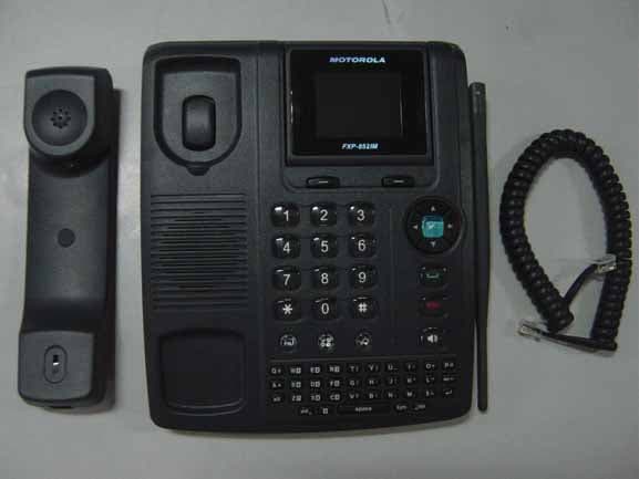
Click to zoom
Application Details
- Equipment Class
- PCB - PCS Licensed Transmitter
- Date of Grant
- May 26, 2011
- Application Purpose
- Original Equipment
- Date of Application
- May 26, 2011
- Equipment Note
- Cordless Fixed Wireless Phone
- Frequency Range
- 1850.20000000 - 1909.80000000
- Company
- Brightstar Corporation
- Country
- United States
Documents & Files
Document Text
Text extracted from the exhibit documents filed with the FCC. Open a document above to read the original.
Users Manual
U ser Manual FXP-852IM Dual band fixed wireless WLL 1 ------------------------------------------------------------------------------------------------------------ USER’S GUIDE This page is intentionally left blank 2 PREFACE WELCOME Congratulations on the purchase of your FXP-852IM product! Please retain your original dated sales receipt for your records. For warranty service of your FXP-852IM product, you will need to provide a copy of your dated sales receipt to confirm warranty status. Thank you for choosing Motorola product. Please read important safety instructions before use. Read and understand all instructions before use. Please retain this guide for future reference. The information contained in the FXP-852IM user guide is believed to be correct at the time of printing. We reserve the right to change or modify any information, product specifications, features or functionality without notice. The contents of the FXP-852IM user guide are provided “as is.” Certain features may not be activated by your service provider, and/or their network settings may limit the feature’s functionality. Additionally, certain features may require a subscription. Contact your service provider for details. 3 CONTENTS SAFETY PRECAUTIONS 6 PRECAUTIONS 6 SAFETY INFORMATION 8 PACKAGE CONTENTS 11 ABOUT YOUR WLLS 12 WLL OVERVIEW 12 INSTALLATION 13 KEY FUNCTION 16 DISPLAY INDICATORS AND ICONS 18 BASIC FUNCTION 19 BASIC OPERATION 19 USING WLL MENUS 24 ENTER LETTERS AND NUMBERS 25 MAIN MENU 27 OVERVIEW OF MENU TREE 27 THE CONTACTS 30 READ 30 ADD 31 MEMORY STATUS 31 SERVICE DIAL 32 SPEED DIAL 32 FIXED DIAL 32 COPY 33 CLEAR ALL RECORDS 33 GROUP 34 4 MY NUMBER 34 MESSAGE 36 WRITE NEW 36 INBOX 37 OUTBOX 38 DRAFTS 38 VOICEMAIL 39 BROADCAST MESSAGE 39 MESSAGE SETTINGS 39 TEMPLATE 40 MEMORY STATUS 40 DIAL RECORDS 41 INCOMING CALL 41 OUTGOING CALL 41 MISSED CALL 41 CALL OPTIONS 42 CALL DURATION 42 SETTINGS 43 WLL SETTINGS 43 MELODY 45 DISPLAY 45 CALL SETUP 46 NETWORK SETUP 49 SECURITY SETUP 50 FACTORY DEFAULT 52 APPLICATIONS 53 ALARM 53 CALCULATOR 53 5 CALENDAR 54 TO DO LIST 54 REFERENCE INFORMATION 55 TECHNICAL INFORMATION 55 REGULATORY 56 FCC NOTICE TO USERS 57 TROUBEL SHOOTING 59 6 SAFETY PRECAUTIONS PRECAUTIONS 1. Please do not try to take out the SIM card of this WLL. This SIM card is a special encrypt card, it cannot be used in other mobile WLLs. It’s the warranty of the product, if you try to rip or remove the SIM Card, the warrant will be not valid and your product will not be warranty in any case. 2. Please do not turn around the antenna at will, in order to avoid create the damage of antenna. 3. Keep the WLL away from water and damp areas. Water or other liquids may cause overheating, electrical leakage, and failure of the WLL. 4. Do not try to disassemble the WLL. This can cause electric shock and failure of the WLL. Tampering will also void the WLL’s warranty. 5. Put the WLL in a safe and stable place. 6. Keep away from dust and heat radiation (i.e. microwaves, stoves, etc.) 7. Try to use the WLL away from ordinary teleWLLs, television sets, radios, and automated office equipment to avoid interference between the devices. 8. Use clean soft dry cloth to wipe the WLL. Do not use any chemical agents. 7 9. Do not put the WLL near explosive or inflammable materials. 10. Use the WLL only within the temperature range of -20 ~60 and humidity range °C °C of 0%~90%. 11. Keep all accessories or batteries out of the reach of small Children or babies. Please instruct children the proper ways of handling WLL during usage. Shock circuit or breakdown may occur and may cause severe danger to user due to improper usage. Shock circuit or breakdown may occur and may cause severe danger to user due to improper usage. 8 SAFETY INFORMATION 1. EXPOSURE TO RADIO FREQUENCY (RF) ENERGY Your WLL contains a transmitter and a receiver. When it is ON, it receives and also sends out radio frequency (RF) signals. When you communicate with your WLL, the system handling your call controls the power level at which your WLL transmits. Your WLL is designed to comply with local regulatory requirements in your country concerning exposure of human beings to RF energy. 2. OPERATIONAL PRECAUTIONS To assure optimal WLL performance and make sure human exposure to RF energy is within the guidelines set forth in the relevant standards; always adhere to the following procedures. 3. EXTERNAL ANTENNA CARE Use only the supplied Motorola approved antenna. Unauthorized antennas, modifications, or attachments could damage the WLL. Do NOT hold the antenna when the WLL is IN USE. Holding the antenna affects call quality and may cause the WLL to operate at a higher power level than needed. In addition, use of unauthorized antennas may result in non-compliance with the local regulatory requirements in your country. 4. WLL OPERATION When placing or receiving a WLL call, hold your WLL as you would use a wireless teleWLL. To maintain compliance with RF energy exposure guidelines, ensure the WLL antenna is at least 10 inches (25centimeters) from your body when transmitting. 5. APPROVED ACCESSORIES Use of accessories not approved by Motorola, including but not limited to batteries and antennas, may cause your WLL to exceed RF energy exposure guidelines. 6. RF ENERGY INTERFERENCE / COMPATIBILITIES 9 Nearly every electronic device is susceptible to RF energy interference from external sources if inadequately shielded, designed, or otherwise configured for RF energy compatibility. In some circumstances your WLL may cause interference. 7. MEDICAL DEVICES 1) Pacemakers Pacemaker manufacturers recommend that a minimum separation of 10 inches (25centimeters) be maintained between the fixed wireless WLL and a pacemaker. Persons with pacemakers should: Always keep the WLL more than 10 inches (25 centimeters) from your pacemaker when the WLL is turned ON. Turn OFF the WLL immediately if you have any reason to suspect that interference is taking place. 2) Hearing Aids Some digita…
Text truncated - open the document above for the full version.
Cover Letter(s)
Date: May 24, 2011 To: Federal Communications Commission, Authorization & Evaluation Division, 7435 Oakland Mills Road, Columbia, MD 21046 Re: Brightstar Corporation FCC ID: WVB-FXP852IM FCC Certification Confidentiality Request Gentlemen: This letter is to comply with 47 CFR 0.457 and 0.459 pertaining to confidentiality material. Brightstar Corporation requests that the following documents regarding this submission for FCC ID: WVB-FXP852IM be kept confidential: Exhibit Type File Name Block Diagram CONF APPENDIX WVB-FXP852IM_Block Diagram.pdf Schematics CONF APPENDIX WVB-FXP852IM _Schematics.pdf Operational Description CONF APPENDIX WVB-FXP852IM_Operational Description.pdf Part list CONF APPENDIX WVB-FXP852IM_BOM.pdf Tune-Up-Procedure CONF APPENDIX WVB-FXP852IM_Tune up procedure.pdf Those documents contain detailed system and equipment description and related information about the product which Brightstar Corporation considers to be confidential proprietary, a custom design and, otherwise, not releasable to the general public. Since this design is a basis form which future technological products will evolve, Brightstar Corporation considers this information would be of benefit to its competitors, and that the disclosure of the information in these documents would give competitors an unfair advantage in the market. Yours Sincerely, Welton Giolo Manager Brightstar Corporation
External Photos
External Photos 1. Front View of EUT 2. Back View of EUT 3. Side View of EUT
ID Label/Location Info
FCC ID Label and Label Location Label Location
Internal Photos
Internal Photos
RF Exposure Info
FCC ID: WVB‐FXP852IM Page 1 of 2 Prediction of MPE limit at given distance Product Descritpion: Cordless Fixed Wireless Phone Type: FXP-852IM 1. Introduction Equation from page 18 of OET Bulletin 65, Edition 97-01 Where: S = power density P = power input to the antenna G = power gain of the antenna in the direction of interest relative to an isotropic radiator R = distance to the center of radiation of the antenna 2. Limits for Maximum Permissible Exposure According to FCC Part 1.1307, systems operating under the provisions of this section shall be operated in a manner the ensures that the public is not exposed to radio frequency energy level in excess of the commission’s guidelines. According to FCC Part 1.1310 RF exposure is calculated. Limits for General Population/ Uncontrolled Exposure Limits for General Population/ Uncontrolled Exposure Frequency Range (MHz) Electric Field Strength(E)(V/m) Magnetic Field Strength (H)(A/m) Power Density (S)(mW/cm 2 ) 0.3-1.34 614 1.63 (100)* 1.34-30 824/f 2.19/f (180/f2)* 30-300 27.5 0.073 0.2 300-1500 f/1500 1500-100,000 1.0 FCC ID: WVB‐FXP852IM Page 2 of 2 3. Test result GSM 850MHz Maximum ERP(dBm): 32.65 Maximum ERP(mW): 1840.77 Source-based time-averaged output power(P*G): 1865 Prediction distance(cm): 20 Predication frequency(MHz): 836.5 Antenna Gain (typical) (dBi): 2 Power density at predication frequency at 20 cm(mW/cm 2 ): 0.371 MPE limit for RF exposure at prediction frequency(mW/cm 2 ): 0.558 GSM 1900MHz Maximum peak output power at antenna input terminal(dBm): 30.34 Maximum peak output power at antenna input terminal(mW): 1081.43 Source-based time-averaged output power(P*G): 595 Prediction distance(cm): 20 Predication frequency(MHz): 1880 Antenna Gain (typical) (dBi): 2 Power density at predication frequency at 20 cm(mW/cm 2 ): 0.118 MPE limit for RF exposure at prediction frequency(mW/cm 2 ): 1.0 4. Conclusion Test result is passed.
Test Report
Report No.: SZ11030101E01 Page 2 of 32 TABLE OF CONTENTS 1. GENERAL INFORMATION .................................................................................................... 3 1.1 EUT Description ......................................................................................................................... 3 1.2 Test Standards and Results ........................................................................................................ 5 1.3 Facilities and Accreditations ...................................................................................................... 6 2. 47 CFR PART 2, PART 22H & 24E REQUIREMENTS ........................................................ 7 2.1 Conducted RF Output Power .................................................................................................... 7 2.2 99% Occupied Bandwidth ....................................................................................................... 11 2.3 Frequency Stability ................................................................................................................... 15 2.4 Conducted Out of Band Emissions ......................................................................................... 17 2.5 Band Edge ................................................................................................................................. 20 2.6 Transmitter Radiated Power (EIRP/ERP) ............................................................................. 23 2.7 Radiated Out of Band Emissions ............................................................................................ 28 Change History Issue Date Reason for change 1.0 May 23, 2011 First edition Report No.: SZ11030101E01 Page 3 of 32 1. GENERAL INFORMATION 1.1 EUT Description EUT Type ............................. : Cordless Fixed Wireless Phone Serial No. .............................. : (n.a, marked #1 by test site) Hardware Version ................. : FXP-852IM_MAIN_V02 Software Version .................. : Applicant .............................. : Manufacturer ........................ : FXP852IM_302KCM_23C Brightstar Corporation 9725 NW 117th Avenue, #300 Miami, FL 33178 LAKIA Networks CO., LTD. 2/F, Unit A, Technology Service Building, Software Garden, 1phase, Xiamen, Fujian, China Zip: 361005 Frequency Range .................. : GSM 850MHz: Tx: 824.20 - 848.80MHz (at intervals of 200kHz); Rx: 869.20 - 893.80MHz (at intervals of 200kHz) GSM 1900MHz: Tx: 1850.20 - 1909.80MHz (at intervals of 200kHz); Rx: 1930.20 - 1989.80MHz (at intervals of 200kHz) Modulation Type................... : GMSK Emission Designators ........... : 300KGXW Power Supply ....................... : Battery Brand Name: GREPOW Model No.: 3 A0600-30 Serial No.: (n.a. marked #1 by test site) Capacitance: 600mAh Rated Voltage: 3.6V Charge Limit: 4.2V Ancillary Equipment A .......... AC Adapter (Charger for Battery) Brand Name: Innov Model Name: IVP045-050-0600 Serial No.: (n.a. marked #1 by test site) Rated Input: 100-240V, 0.2A, 50/60Hz Rated Output: 5V, 0.6A Manufacturer: Innov Electronics Tech Co., Ltd. Manufacturer Address: NO.1 XIANGHONG ROAD, HI-TECHINDUSTRI ZONE XIANG-AN, XIAMEN, CHINA Note 1: The transmitter (Tx) frequency arrangement of the Cellular 850MHz band used by the EUT can be represented with the formula F(n)=824.2+0.2*(n-128), 128<=n<=251; the lowest, middle, highest channel numbers (ARFCHs) used and tested in this report are separately 128 (824.2MHz), 190 (836.6MHz) and 251 (848.8MHz). Report No.: SZ11030101E01 Page 4 of 32 Note 2: The transmitter (Tx) frequency arrangement of the PCS 1900MHz band used by the EUT can be represented with the formula F(n)=1850.2+0.2*(n-512), 512<=n<=810; the lowest, middle and highest channel numbers (ARFCHs) used and tested in this report are separately 512 (1850.2MHz), 661 (1880.0MHz) and 810 (1909.8MHz). Note 3: For a more detailed description, please refer to Specification or User’s Manual supplied by the applicant and/or manufacturer. Report No.: SZ11030101E01 Page 5 of 32 1.2 Test Standards and Results The objective of the report is to perform testing according to 47 CFR Part 2, Part 22 and Part 24 for the EUT FCC ID Certification: No. Identity Document Title 1 47 CFR Part 2 (10-1-09 Edition) Frequency Allocations and Radio Treaty Matters; General Rules and Regulations 2 47 CFR Part 22 (10-1-09 Edition) Public Mobile Services 3 47 CFR Part 24 (10-1-09 Edition) Personal Communications Services Test detailed items/section required by FCC rules and results are as below: No. Section Description Result 1 2.1046 Conducted RF Output Power PASS 2 2.1049 20dB Occupied Bandwidth PASS 3 2.1055 22.355 24.235 Frequency Stability PASS 4 2.1051 2.1057 22.917 24.238 Conducted Out of Band Emissions PASS 5 2.1051 2.1057 22.917 24.238 Band Edge PASS 6 22.913 24.232 Transmitter Radiated Power (EIPR/ERP) PASS 7 2.1053 2.1057 22.917 24.238 Radiated Out of Band Emissions PASS NOTE:Measurement method according to TIA/EIA 603.C-2004. Report No.: SZ11030101E01 Page 6 of 32 1.3 Facilities and Accreditations 1.3.1 Facilities Shenzhen Morlab Communications Technology Co., Ltd. Morlab Laboratory is a testing organization accredited by China National Accreditation Service for Conformity Assessment (CNAS) according to ISO/IEC 17025. The accreditation certificate number is L3572. All measurement facilities used to collect the measurement data are located at 3/F, Electronic Testing Building, Shahe Road, Xili, Nanshan District, Shenzhen, 518055 P. R. China. The test site is constructed in conformance with the requirements of ANSI C63.7, ANSI C63.4 and CISPR Publication 22; the FCC registration number is 741109. 1.3.2 Test Environment Conditions During the measurement, the environmental conditions were within the listed ranges: Temperature (°C): 15 - 35 Relative Humidity (%): 30 -60 Atmospheric Pressure (kPa): 86-106 Report No.: SZ11030101E01 Page 7 of 32 2. 47 CFR PART 2, PART 22H & 24E REQUIRE…
Text truncated - open the document above for the full version.
Test Setup Photos
Test Setup Photos 1. CSE 2. RSE
Contact Information
Applicant
Welton Giolo(Project Manager)
Technical Contact
Shenzhen Morlab Communications Technology Co.,LtdWu Xuewen
+86-755-86120298
FL.3,Electronic Testing Bld, Shahe Rd · Nanshan · China
Test Firm
Shenzhen Morlab Communications Technology Co.,LtdShu Luan
Technical Specifications
| # | Rule Parts | Frequency Range | Power Output | Emission | Tolerance |
|---|---|---|---|---|---|
| 2 | 24E | 1.85 GHz - 1.91 GHz | 1.19 W | 260KGXW | 0.1 ppm |
Other Applications from Brightstar Corporation
WVBAC622X
Jan 03, 2016CDMA mobile phone
Equipment Class
PCE - PCS Licensed Transmitter held to ear
WVB140M
Nov 08, 2015Smartphone
Equipment Class
JBP - Part 15 Class B Computing Device Peripheral
WVBAL660X
Nov 04, 20154G mobile phone
Equipment Class
DTS - Digital Transmission SystemWVBAL620
Nov 01, 2015Mobile phone
Equipment Class
DTS - Digital Transmission System
WVB145M
Oct 27, 2015Mobile phone
Equipment Class
PCE - PCS Licensed Transmitter held to ear