WVJ-AB00010492701Window Opener Transmitter
Andersen Corporation
Click to zoom
Application Details
- Equipment Class
- DSR - Part 15 Remote Control/Security Device Transceiver
- Date of Grant
- Mar 07, 2013
- Application Purpose
- Original Equipment
- Date of Application
- Mar 06, 2013
- Equipment Note
- Window Opener Transmitter
- Frequency Range
- 868.20000000 - 868.20000000
- Company
- Andersen Corporation
- Country
- United States
Documents & Files
Document Text
Text extracted from the exhibit documents filed with the FCC. Open a document above to read the original.
Users Manual
Power Window Control System Installation and Programming Guide Power Window Control System Installation and Prog ramming Guide 2 000XXXX Power Window Control System Window Preparation Existing Window or New Window............................3-XX Power Window Control System Installation New Construction....................................5-11 Existing Construction .................................12-19 Power Window Control System Programming Console Programming................................21-22 Remote Control Programming.............................23-24 Power Window Control System Operation...........................25 Power Window Control System Wiring Diagram........................26 Power Window Control System Operation Codes.......................27 Trouble Shooting.....................................28-30 Regulatory Compliance....................................31 Warranty.........................................32-33 Table of Contents 3 000XXXX Power Window Control System Window Preparation Power Window Control System Window Preparation XX Use caution when working at elevated heights and around unit openings. Follow manufacturers’ instructions for ladders and/or scaffolding. Failure to do so may result in injury or death. Sea cauteloso al trabajar en lugares elevados y cerca de las aberturas de la unidad. Siga las instr ucciones del fabricante para el uso de escaleras y/o andamios. Si no lo hiciera, podrían producirse lesiones o la muerte. Follow manufacturers’ instructions for hand or power tools. Always wear saf ety glasses. Failure to do so may result in injury and/or product damage. Siga las instrucciones del fabricante para el uso de herramientas eléctricas o manuales. Utilice siempre gafas de seguridad. Si no lo hiciera, podrían producirse lesiones y/o daños al producto. XXXXXXX BA Revised 01/11/13 Power Window Control System Installation Guide Power Window Control System Installation Guide for Andersen® Awning Windows with Power Windows for Andersen® Awning Windows with Power Windows Thank you for choosing Andersen. / Gracias por elegir Andersen. ▶For installation in new construction, see page 5. ▶F or installation in new construction, see page 5. ▶F or installation in existing construction, see page 12. ▶For installation in existing construction, see page 12. Parts Included / Parts Included (1) Power Box Components / Power Box Components (1) Key Pad / Key Pad (1) Mounting Ring / Mounting Ring (7) 1/2" Screws / 1/2" Screws (1) Installation Instructions / Installation Instructions Supplies Needed / Supplies Needed ∙18-3 Conductor Wire / 18-3 Strand Conductor Wire ∙14-2(min) High Voltage Wire / 14-2(min) High Voltage Wire ∙1-5/8" Dr ywall Screws / 1-5/8” Drywall Screws ∙Outlet Box Cable Clamps / Outlet Box Cable Clamps ∙W ire Staples / Wire Staples ∙Dr ywall Saw / Drywall Saw Tools Needed / Tools Needed ∙Safety glasses / Safety glasses ∙T ape measure / Tape measure ∙Drill/Driv er / Drill/Driver ∙W ire Cutter / Wire Cutter ∙W ire Stripper / Wire Stripper ∙Phillips Head Scre w Driver / Phillips Head Screw Driver ∙1/2" Spade Bit / 1/2" Spade Bit ∙T ape Measure / Tape Measure ∙Hammer / Hammer ∙P aper Clip / Paper Clip ∙3/8" Drill Bit / 3/8” Drill Bit Power Box Power Box Mounting Ring Mounting Ring Key Pad Key Pad For questions call 1-888-888-7020. For more information and/or guides visit andersenwindows.com. Please leave this guide with building owner. Si tiene alguna pregunta llame al 1-888-888-7020. Para obtener más información y/o guías, visite andersenwindo ws.com. Deje esta guía con el dueño de la construcción. Thank you for choosing Andersen. / Gracias por elegir Andersen. ▶Read guide from beginning to end before star ting installation. Read all warnings and cautions during unit installation. Lea completamente la guía antes de comenzar la instalación. Lea y respete todas las advertencias y precauciones durante la instalación de la unidad. This document is under construction do not print, publish, or distribute ▶Check with your local building code official to identify and confirm compliance with local building code requirements. Consulte los códigos locales de construcción para identificar y confirmar que se cumplan los requisitos del código de construcción. “Andersen” and all other marks where denoted are trademarks of Andersen Corporation. ©2012-2012 Andersen Corporation. All rights reserved. “Andersen” y las demás marcas que aparezcan son marcas registradas de Andersen Corporation. ©2012-2012 Andersen Corporation. Todos los derechos reser vados. Electric Operator Electric Operator 5 000XXXX 1 3 2 Interior Interior Interior Install window following installation instructions. Install window following installation instructions. Drill 3/8" hole through side extension jamb as shown. Drill 3/8” hole through side extension jamb as shown. Locate power box on interior wall, 54" above floor (48" top of box - ADA locations) and within 50 feet of windo w. Attach box to stud using three drywall screws. Locate power box on interior wall, 54” above floor (48” top of box - ADA locations) and within 50 feet of windo w. Attach box to stud using three drywall screws. 4 Interior Remove tape. Remove tape. 54" (48" top of box - ADA locations) 54" (48" top of box - ADA locations) Tape Tape Tape Tape Power Window Control System Installation (New Construction) Power Window Control System Installation (New Construction) ▶See wiring diagram for proper wire configuration prior to starting ▶See wiring diagram for proper wire configuration prior to star ting XX 6 000XXXX Run 18-3 wire through side jamb between power box and awning window(s) and run 14-2 (min.) wire to power box location. Run 18-3 wire through side jamb between power box and awning window(s) and run 14-2 (min.) wire to po wer box location. Run 18-3 wire to midpoint of window. Run 18-3 wire to midpoint of windo w. 18-3 Wire 18-3 Wire 14-2 (min.) Wire 14-2 (min.) Wire Side Jamb Side Jamb 5 Interior 6 Interior Plug pigtail wire into e…
Text truncated - open the document above for the full version.
Cover Letter(s)
FCC ID: WVJ-AB00010492701 D.L.S. ELECTRONIC SYSTEMS, INC. 166 South Carter Street Genoa City, WI 53128 February 28, 2013 FCC Authorization & Evaluation Division 7435 Oakland Mills Road Columbia, Maryland 21046 Gentlemen: We are submitting for Andersen Corporation, a Power Window Driver, Model Number: 9018359, with an FCC ID: WVJ-AB00010492701 for Certification. This unit has been tested and complies to Part 15, Subpart C. If there are any questions in regard to this application, please call D.L.S. Electronic Systems, Inc. at (262) 279-0210. Enclosed you will find a copy of our test report with the information and results of tests that is required under Part 15, Section 15.231. Thank you for your assistance in this matter. Sincerely, William M. Stumpf DLS/js
Cover Letter(s)
166 South Carter Street, Genoa City, WI 53128 Request for Confidentiality Date: February 28, 2013 FCC Authorization & Evaluation Division 7435 Oakland Mills Road Columbia, Maryland 21046 RE: Certification Application FCC ID: WVJ-AB00010492701 Pursuant to 47 CFR Section 0.459 Andersen Corporation understands that requests for non disclosure and confidential treatment is being made for the following information as stated under the Code of Federal Regulations Chapter 47, Part 0.459: • Block Diagram • Schematics • Description of Operation The above materials contain trade secrets, proprietary and technical information that would customarily be guarded from competitors under 47 CFR section 0.457(d)(2). Disclosure or publication of any portion of this company confidential material to other parties could cause substantial competitive harm and provide unjustified benefits for competitors. Andersen Corporation understands that pursuant to 47 CFR section 0.457(d)(1)(ii) disclosure of the applicant and all accompanying documentation will not be made before the date of the grant. Thank you for your attention to this matter. Signatory William M. Stumpf OATS Manager D.L.S. Electronic Systems, Inc.
External Photos
External Photos Company: Andersen Corporation Model: 9018359 Side 1 Side 2
ID Label/Location Info
FCC – IC – MN Label Driver: M/N: 9018359 IC: 10511A-AB000104927 FCC ID: WVJ-AB00010492701 Label Size = 1.125" x .375" Font Size = 5.5
Internal Photos
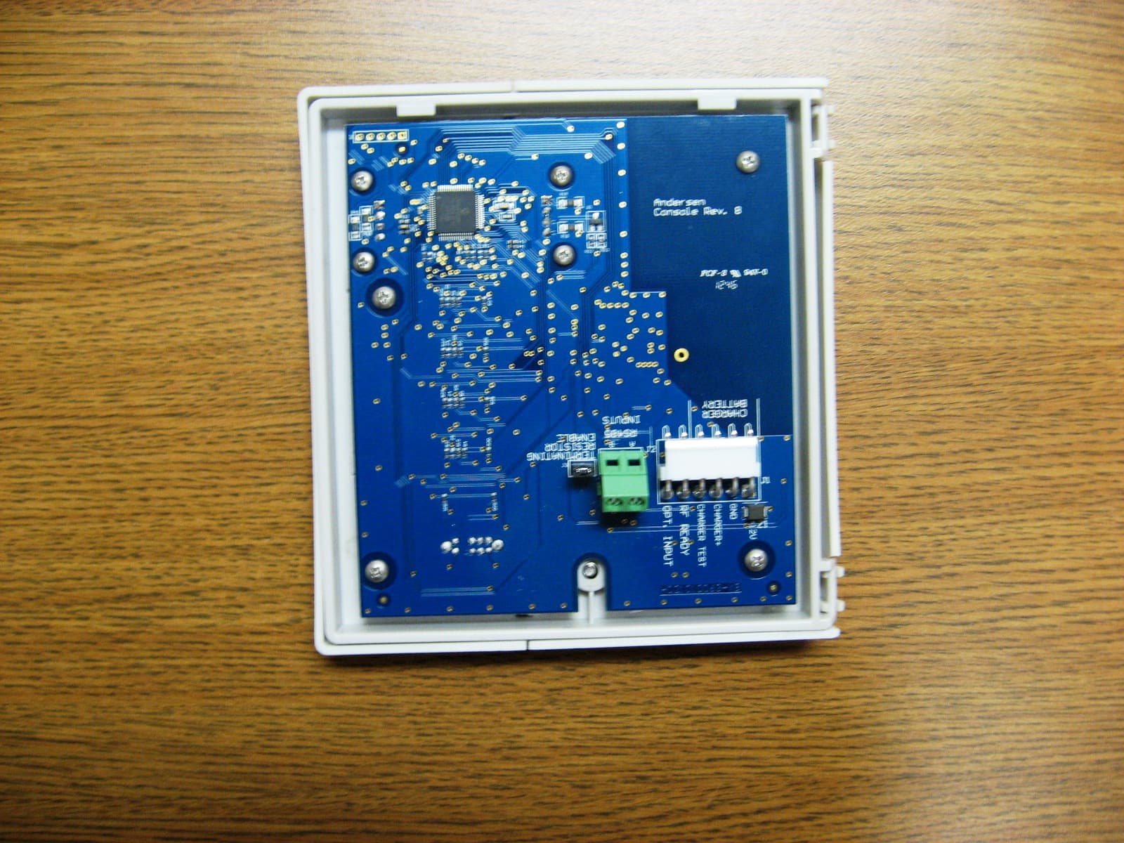
Internal Photos Company: Andersen Corporation Model: 9018359 Circuit Board - Side 1 - 1 of 2 Circuit Board - Side 1 - 2 of 2 Circuit Board - Side 2 - 1 of 2 Circuit Board - Side 2 - 2 of 2 Circuit Board - Edge Circuit Board - Close-up of Antenna
Test Report
166 South Carter, Genoa City, WI 53128 Page 1 of 52 Company: Andersen Corporation Model Tested: 9018359 Report Number: 18706 Project Number: 5701 i. Cover Page Code of Federal Regulations 47 Part 15 – Radio Frequency Devices Subpart C – Intentional Radiators Section 15.231 Periodic operation in the band 40.66 - 40.70 MHz and above 70 MHz Including Verification data for Subpart B - Unintentional Radiators Sections 15.107 & 15.109 for the Receiver THE FOLLOWING MEETS THE ABOVE TEST SPECIFICATIONS Formal Name: Power Window Driver Kind of Equipment: Power Window Driver with transceiver Frequency Range: 868.2 MHz Test Configuration: Tabletop Model Number(s): 9018359 Model(s) Tested: 9018359 Serial Number(s): none (Test Sample) Date of Tests: January 23 to February 14, 2013 Test Conducted For: Andersen Corporation 100 Fourth Avenue North Bayport, Minnesota 55003-1096, USA NOTICE: “This test report relates only to the items tested and must not be used by the client to claim product endorsement by NVLAP or any agency of the U.S. Government”. Please see the "Description of Test Sample" page listed inside of this report. © Copyright 1983 - 2013 D.L.S. Electronic Systems, Inc. COPYRIGHT NOTICE This report must not be reproduced (except in full), without the approval of D.L.S. Electronic Systems, Inc. 166 South Carter, Genoa City, WI 53128 Page 2 of 52 Company: Andersen Corporation Model Tested: 9018359 Report Number: 18706 Project Number: 5701 ii. Signature Page SIGNATURE PAGE Tested By: Craig Brandt Test Engineer Reviewed By: William Stumpf OATS Manager Approved By: Brian Mattson General Manager 166 South Carter, Genoa City, WI 53128 Page 3 of 52 Company: Andersen Corporation Model Tested: 9018359 Report Number: 18706 Project Number: 5701 iii. Table of Contents Table of Contents i. Cover Page .......................................................................................................................................1 ii. Signature Page .................................................................................................................................2 iii. Table of Contents .............................................................................................................................3 iv. NVLAP Certificate of Accreditation ...............................................................................................4 1.0 Summary of Test Report ..................................................................................................................5 2.0 Introduction ......................................................................................................................................5 3.0 Test Facilities ...................................................................................................................................5 4.0 Description of Test Sample ..............................................................................................................6 5.0 Test Equipment ................................................................................................................................7 6.0 Test Arrangements ...........................................................................................................................7 7.0 Test Conditions ................................................................................................................................8 8.0 Modifications Made To EUT For Compliance ................................................................................8 9.0 Additional Descriptions ...................................................................................................................8 10.0 Results ..............................................................................................................................................8 11.0 Conclusion .......................................................................................................................................8 Appendix A – Test Photos ...........................................................................................................................9 Appendix B – Measurement Data ..............................................................................................................19 1.0 Emission Bandwidth – 20 dB ................................................................................................... 19 2.0 Automatic Deactivation ............................................................................................................ 21 3.0 Field Strength of Emissions – Fundamental and Spurious ....................................................... 23 4.0 Duty Cycle Correction .............................................................................................................. 32 5.0 AC Line Conducted Emissions ................................................................................................. 34 6.0 Unintentional Radiated Emissions ............................................................................................ 39 166 South Carter, Genoa City, WI 53128 Page 4 of 52 Company: Andersen Corporation Model Tested: 9018359 Report Number: 18706 Project Number: 5701 iv. NVLAP Certificate of Accreditation 166 South Carter, Genoa City, WI 53128 Page 5 of 52 Company: Andersen Corporation Model Tested: 9018359 Report Number: 18706 Project Number: 5701 1.0 Summary of Test Report It was determined that the Andersen Corporation Power Window Driver, Model 9018359, complies with the requirements of CFR 47 Part 15 Subpart C Section 15.231. Subpart C Section 15.231 Applicable Technical Requirements Tested: Section Description Procedure Note Compliant? 15.231(c) 20 dB Emission Bandwidth ANSI C63.4-2009 & ANSI C63.10-2009 1,2 Yes 15.231(a)(1) and 15.231(a)(2) Automatic Deactivation ANSI C63.4-2009 & ANSI C63.10-2009 1,2 Yes 15.231(b) Field Strength of Emissions - Fundamental and Spurious - ANSI C63.4-2009 & ANSI C63.10-20…
Text truncated - open the document above for the full version.
Contact Information
Applicant
Graham Duthie(Technical Leader)
Technical Contact
D. L. S. Electronic Systems, Inc.William (Bill) Martin Stumpf
[email protected]262-279-0210
166 South Carter Street · Genoa City, Wisconsin · United States
Test Firm
DLS Electronic Systems, Inc.William Stumpf
Technical Specifications
| # | Rule Parts | Frequency Range | Power Output |
|---|---|---|---|
| 1 | 15.231 | 868.2 MHz - 868.2 MHz | - |
Other Applications from Andersen Corporation
WVJ-AB00010492901
Mar 11, 2013Wall-mounted Window Control Transmitter
Equipment Class
DSR - Part 15 Remote Control/Security Device Transceiver
WVJ-AB00010492801
Mar 07, 2013Hand-held Remote Control Transmitter for Windows
Equipment Class
DSR - Part 15 Remote Control/Security Device Transceiver
WVJ-CB00010592902
May 20, 2012INTRUSION DETECTOR SENSOR
Equipment Class
DXX - Part 15 Low Power Communication Device Transmitter
WVJ-CB00010522402
May 13, 2012INTRUSION DETECTOR SENSOR
Equipment Class
DXX - Part 15 Low Power Communication Device Transmitter
WVJ-CB00010519902
May 06, 2012INTRUSION DETECTOR SENSOR
Equipment Class
DSC - Part 15 Security/Remote Control Transmitter