WVTWOUXUN05TWO-WAY RADIO
Quanzhou Wouxun Electronics Co., Ltd.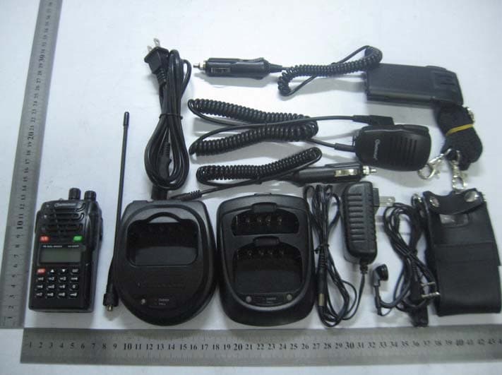
Click to zoom
Application Details
- Equipment Class
- TNF - Licensed Non-Broadcast Transmitter Held to Face
- Date of Grant
- Jun 16, 2011
- Application Purpose
- Original Equipment
- Date of Application
- Jun 16, 2011
- Equipment Note
- TWO-WAY RADIO
- Frequency Range
- 220.00000000 - 222.00000000
- Country
- China
Documents & Files
Document Text
Text extracted from the exhibit documents filed with the FCC. Open a document above to read the original.
Users Manual
To ensure that your expose to RF electromagnetic energy is Within the FCC allowable limits for occupational use, alwaysAdhere to the following guidelines: z DO NOT operate the radio without a proper antenna attached, as this may damaged the radio And may also cause you to exceed FCC RF exposure limits, A proper antenna is the antenna Supplied with this radio by the manufacturer or antenna specifically authorized by the manufacturer for use with this radio. z DO NOT transmits for more than 50% of total radio use time (“50% duty cycle). Transmitting more than 50% of the time can cause FCC RF exposure compliance requirements to be exceeded. The radio is transmitting when the “TX indicator” lights red. You can cause the radio to transmit by pressing the “PTT” switch. z ALWAYS kepp the antenna at least 2.5cm (1 inch) away from the body when transmitting and Only use the belt-clip which is listed in instructions when attaching the radio to your belt, etc., to ensure FCC RF exposure compliance requirements are not exceeded. To provide the recipients of your transmission the best sound quality, hold the antenna at least 5cm(2 inches) from your mouth, and slightly off to one side. The information listed above provides the user with the information needed to make him or her aware of RF exposure, and what to do to as-sure that this radio operates with the FCC RF exposure limits of this radio. NOTE 1: This equipment has been tested and found to comply with the part 15 of the FCC rules. These limits are designed to provide reasonable protection against harmful interference in a residential installation. This equipment generates, uses and can radiate radio frequency energy and, if not installed and used in accordance with the instructions, may cause harmful interference to radio communications. However, there is no guarantee that interference will not occur in a particular installation. If this equipment does cause harmful interference to radio or television reception, which can be determined by turning the equipment off and on, the user is encouraged to try to correct the interference by one or more of the following measures: - Reorient or relocate the receiving antenna. - Increase the separation between the equipment and receiver. -Connect the equipment into an outlet on a circuit different from that to which the receiver is connected. -Consult the dealer or an experienced radio/TV technician for help. Any changes or modifications not expressly approved by the manufacturer could void the user’s authority to operate the equipment. SAFETY TRAINING INFORMATION This Radio has been tested and complies with the Federal Communications Commission(FCC) RF exposure limits for Occupational Use/Controlled exposure environment. In addition, it complies with the following Standards and Guidelines: □ 47 CFR part 2 sub-part j, United States Federal Communications Commission, Code of Federal Regulations □ FCC OET Bulletin 65 Edition 01-01(2001) Supplement C, Evaluating Compliance with FCC Guidelines for Human Exposure to Radio Frequency Electromagnetic Fields. □ ANSI/IEEE C95.1-1992, IEEE Standard for Safety Levels with Respect to Human Exposure to Radio Frequency Electromagnetic Fields, 3kHz to 300GHz. □ ANSI/IEEE C95.3-1992, IEEE Recommended Practice for the Measurement of Potentially Hazardous Electromagnetic Fields-RF and Microwave. WARNING: This radio generates RF electromagnetic energy during transmit mode. This radio is designed for and classified as Occupational Use Only, meaning it must be used only during the course of employment by individuals aware of the hazards, and the ways to minimize such hazards. This radio is not intended for use by the General Population in an uncontrolled environment. CAUTION: To ensure that your expose to RF electromagnetic energy is within the FCC allowable limits for occupational use, always adhere to the following guidelines: RF Exposure Compliance and Control Guidelines and Operating Instructions ■ This radio is NOT approved for use by the general population in an uncontrolled environment. This radio is restricted to occupational use, work related operations only where the radio operator must have the knowledge to control its RF exposure conditions. ■ When transmitting, hold the radio in a vertical position with its microphone 1 to 2 inches (2.5 to 5.0cm) away from your mouth and keep the antenna at least 1 inch (2.5cm) away from your head and body. ■ The radio must be used with a maximum operating duty cycle not exceeding 50%, in typical Push-to-Talk(PTT) configurations, DO NOT transmit for more than 50% of total radio use time (50% duty cycle). Transmitting more than 50% of the time can cause FCC RF exposure compliance requirements to be exceeded. The radio is transmitting when the red LED on the top of the radio is illuminated. You can cause the radio to transmit by pressing the PTT button. Note: Time-out timer: The selected channel has been programmed for Time-Out timer, you must limit the length of each transmission, Wile transmitting, a beep will sound 10 seconds before time-out. Another beep will sound just before the deadline; The TX indicator will disappear the transmission will cease soon thereafter. To resume transmitting, you must release the PTT switch and wait for the “penalty timer “ to expire (if you press the PTT switch before this timer expires, the timer restarts, and you will have to wait another “penalty” period). To ensure that the radio must be used with a maximum operating duty cycle not exceeding 50%, but for VOX mode, the maximum operating duty cycle may be up to 100%. ■ DON NOT transmit when the radio is used in Body Worn configuration with the following accessory: belt-clip(CLIP-18). It must be used ONLY for (1) there is a 1 inch (2.5cm) distance from the body during transmitting, (2) monitoring purposes, using the speaker only and (3) for carrying purposes. The information listed above provides the user with the information needed to make him or…
Text truncated - open the document above for the full version.
Cover Letter(s)
Quanzhou Wouxun Electronics Co., Ltd. No.928 Nanhuan Road, Jiangnan High Technology Industry Park, Quanzhou, Fujian, China June, 4, 2011 Federal Communications Commission Authorization and Evaluation Division Confidentiality Request regarding application for certification of FCC ID: WVTWOUXUN05 Pursuant to Sections 0.457 and 0.459 of the Commission’s Rules, we hereby request confidential treatment of information accompanying this application as outlined below: Exhibit Type File Name Schematics CONF_WVTWOUXUN05_FCC_Schematics.pdf Block Diagram CONF_WVTWOUXUN05_FCC_BlockDiagram.pdf Operational Description CONF_WVTWOUXUN05_FCC_OperationalDescription.pdf The above materials contain trade secrets and proprietary information not customarily released to the public. The public disclosure of these materials may be harmful to the applicant and provide unjustified benefits to its competitors. The applicant understands that pursuant to Section 0.457 of the Rules, disclosure of this application and all accompanying documentation will not be made before the date of the Grant for this application.
Cover Letter(s)
Quanzhou Wouxun Electronics Co., Ltd. No.928 Nanhuan Road, Jiangnan High Technology Industry Park, Quanzhou, Fujian, China Letter of Attestation June 4, 2011 Equipment Authorization Division Office of Engineering and Technology Federal Communications Commission 7435 Oakland Mills Road Columbia, MD 21046 In re: Quanzhou Wouxun Electronics Co., Ltd. FCC ID: WVTWOUXUN05 90.203(e) and (g) statement request Gentlemen: This equipment meets the requirements of FCC Rules, Parts 90.203 (e) and (g) as applicable. Programming of this product’s transmit frequencies can be performed only by the manufacturer or be service or maintenance personnel. The operator cannot program transmit frequencies using the equipment’s external operation.
Cover Letter(s)
Quanzhou Wouxun Electronics Co., Ltd. No.928 Nanhuan Road, Jiangnan High Technology Industry Park, Quanzhou, Fujian, China 1 June 4, 2011 Timco Engineering, Inc. 849 NW State Road 45 P.O. Box 370 Newberry, Florida 32669 Subject: FCC ID: WVTWXOUN05 justification letter for expanded frequency range 136 - 174 MHz and 217-222MHz Gentlemen: The KG-816 Portable radio was designed to operate in the frequency bands 136-174MHz and 217-222MHz To aid equipment authorization in other countries that accept the United States FCC Grant for Certification, Quanzhou Wouxun Electronics Co., Ltd. is requesting that the FCC list the frequencies 136-174MHz and 217-222MHz under FCC Rules Parts 90 on the FCC Grant. For the FCC’s Rule Parts 90 applications, this radio is used in systems by Federal and Public Safety agencies including Police, Fire, and Emergency Medical Services, etc. as indicated in the table below. Frequency Range (MHz) Part 90 Feds Grant Notes 136-150.8 X EF, BE 150.8-161.6250 X EF, BE 161.775-173.4 X X EF, BE 173.4-174 X EF, BE 217-220 X X EF, BE 220-222 X X EF, BE Equipment programming is the responsibility of Authorized Service Personnel. In addition, the radio complies with 47 CFR Part 90.203(e), in that the operator cannot directly program the transmit frequencies using the normally accessible external controls.
External Photos
Quanzhou Wouxun Electronics Co., Ltd. Model: KG-UVD1P REPORT NO.: STR11048040I FCC PART 90 EXHIBIT 2 - EUT EXTERNAL PHOTOGRAPHS EUT View 1 EUT View 2 Quanzhou Wouxun Electronics Co., Ltd. Model: KG-UVD1P REPORT NO.: STR11048040I FCC PART 90 EUT View 3 EUT View 4 Quanzhou Wouxun Electronics Co., Ltd. Model: KG-UVD1P REPORT NO.: STR11048040I FCC PART 90 Antenna Connector View
ID Label/Location Info
Quanzhou Wouxun Electronics Co., Ltd. Model: KG-UVD1P REPORT NO.: STR11048040I FCC PART 90 EXHIBIT 1- PRODUCT LABELING Proposed FCC ID Label Format Specifications : Text is Black in color and justified. Labels are printed in indelible ink on permanent adhesive silk-screened onto the EUT or shall be affixed at a conspicuous location on the EUT. Proposed Label Location on EUT FCC ID Label Location
ID Label/Location Info
Quanzhou Wouxun Electronics Co., Ltd. Model: KG-UVD1P REPORT NO.: STR11048040I FCC PART 90 EXHIBIT 1- PRODUCT LABELING Proposed FCC ID Label Format Specifications : Text is Black in color and justified. Labels are printed in indelible ink on permanent adhesive silk-screened onto the EUT or shall be affixed at a conspicuous location on the EUT. Proposed Label Location on EUT FCC ID Label Location
ID Label/Location Info
2011-06-13 Equipment Authorization Division Office of Engineering and Technology Federal Communications Commission 7435 Oakland Mills Road Columbia, MD 21046 Ref: FCC ID: WVTWOUXUN05 Dear Sirs: Quanzhou Wouxun Electronics Co., Ltd. requests acceptance of the labeling proposal described below for transceivers bearing FCC identifier WVTWOUXUN05. The subject transceivers are compact handheld models as shown in figure 1, authorized under 47CFR Part 80 for maritime services. Figure 1 Because the majority of the transceiver housing is composed of display, speaker, operating controls, and a removable battery pack, there is extremely limited space available to attach the required label carrying the FCC identifier. Attaching the label to the battery pack is not acceptable because the battery pack is a removable item. For this reason, Quanzhou Wouxun Electronics Co., Ltd. proposes placing the label carrying the FCC identifier inside the battery compartment as shown in figure 2. Figure 2 The consumer packaging for these models includes the battery pack as a separate item, NOT installed on the radio. As such, the FCC identifier will be readily visible to the user before the battery pack is installed and whenever the battery pack is removed or replaced. In this location, the label will also be protected from physical abuse and remain readable for the anticipated life of the device. The consumer packaging for these models is a "gift box" which does not allow the transceiver to be seen at time of purchase. In order to meet the requirements of 47CFR Part 2.925 (d), Quanzhou Wouxun Electronics Co., Ltd. will add the FCC identifier " WVTWOUXUN05" to the outside of the consumer "gift box" packaging.
Internal Photos
Quanzhou Wouxun Electronics Co., Ltd. Model: KG-UVD1P REPORT NO.: STR11048040I FCC PART 90 EXHIBIT 3 - EUT INTERNAL PHOTOGRAPHS EUT Housing and Board View Solder Board-Component View 1 Quanzhou Wouxun Electronics Co., Ltd. Model: KG-UVD1P REPORT NO.: STR11048040I FCC PART 90 Solder Board-Component View 2 Solder Board-Component View 3 Quanzhou Wouxun Electronics Co., Ltd. Model: KG-UVD1P REPORT NO.: STR11048040I FCC PART 90 Solder Board-Component View 4 Solder Board-Component View 5
Parts List/Tune Up Info
Parts List The Front parts on PC Board Spec. USE/Function encapsulationDigit. No Quat. NC Laminated Capacitance C0402 C148 C824 C657 C623 C167 C165 C161 C394 C390 9 104P Laminated Capacitance C0402 C833 C846 C845 C843 C842 C840 C837 C830 C827 C817 C814 C812 C641 C640 C638 C636 C634 C631 C624 C592 C589 C517 C514 C513 C511 C164 C162 C158 C614 C233 C841 C396 C389 R643 34 103P Laminated Capacitance C0402 C675 C364 C847 C844 C839 C825 C815 C813 C655 C625 C612 C611 C596 C545 C206 C168 C166 C163 C159 C138 C615 C393 C388 C237 C131 25 470P Laminated Capacitance C0402 C190 C639 C541 C134 C643 C616 6 102P Laminated Capacitance C0402 C360 C838 C829 C658 C652 C516 C512 C373 C169 C160 C156 C645 C644 C617 C397 C927 R631 17 68P Laminated Capacitance C0402 C590 1 220P Laminated Capacitance C0402 C851 C850 C832 C831 C656 C552 6 27P Laminated Capacitance C0402 C849 C848 2 223P Laminated Capacitance C0402 C836 C816 C635 C633 C626 C597 C216 C157 8 683P Laminated Capacitance C0402 C828 C826 2 100P Laminated Capacitance C0402 C823 C822 C821 C820 C632 C646 6 200P Laminated Capacitance C0402 C653 C651 2 272P Laminated Capacitance C0402 C637 1 680P Laminated Capacitance C0402 C630 C627 2 473P Laminated Capacitance C0402 C628 1 24P Laminated C0402 C598 C594 C588 3 Capacitance 20P Laminated Capacitance C0402 C521 1 105P Laminated Capacitance C0402 C642 1 5P Laminated Capacitance C0402 C534 1 8P Laminated Capacitance C0402 C535 1 NC Laminated Capacitance C0603 C136 C431 2 105P Laminated Capacitance C0603 C647 1 10uF Laminated Capacitance C0805 C662 C661 E518 C196 C195 C193 C456 C457 8 2.2uF Laminated Capacitance C0805 E615 E614 C455 C194 4 4.7uF Laminated Capacitance C0805 E612 E611 E117 3 RED LED D0603 D815 1 GREEN LED D0603 D814 1 RLS4148 Diode D-ESC D811 D518 D326 D169 D517 5 LED LED LED D926 1 RLS4148 Diode USC D611 D610 2 1SS372 Diode USM D812 D612 2 32.768KHz crystal MC-146 CR811 1 2.5 mm Headset jack ST-104 JK513 1 3.5 mm Mic jack ST-301 JK611 1 JP20 20chip block JP-20-2L JP811 1 CH100nH Fixed inductance L0603 L811 L611 L520 L517 4 CH68nH Fixed inductance L0603 L519 L518 2 4.7K Laminated Capacitance R0402 R221 R854 R840 R839 R630 R625 R624 R623 R618 R359 R216 R144 R133 R219 R927 C629 16 1K Laminated Capacitance R0402 R222 R132 R824 R669 R668 R663 R815 R814 8 0R Laminated Capacitance R0402 R152 R675 R859 R838 R641 R632 R856 7 10K Laminated Capacitance R0402 R674 R673 R672 R671 R813 R811 R633 R627 R651 R163 10 22K Laminated R0402 R384 R852 R848 R637 R620 R576 R862 R134 8 Capacitance 180K Laminated Capacitance R0402 R131 R646 2 560K Laminated Capacitance R0402 R861 1 220K Laminated Capacitance R0402 R860 R858 R828 R819 R578 R218 R112 7 100R Laminated Capacitance R0402 R855 R664 R662 R617 R572 5 68K Laminated Capacitance R0402 R853 R644 2 100K Laminated Capacitance R0402 R851 R843 R818 R642 4 47K Laminated Capacitance R0402 R850 R817 R622 R596 R135 R118 R116 R115 R113 R648 R389 R379 R667 13 91K Laminated Capacitance R0402 R846 1 5.6K Laminated Capacitance R0402 R845 R844 R634 3 33K Laminated Capacitance R0402 R842 R841 R629 R628 R626 R621 R613 R137 8 120K Laminated Capacitance R0402 R830 1 330R Laminated Capacitance R0402 R829 R665 2 150R Laminated Capacitance R0402 R822 R821 2 2.2K Laminated Capacitance R0402 R820 R666 R639 R573 R119 R114 R390 R378 8 47R Laminated Capacitance R0402 R816 1 18K Laminated Capacitance R0402 R640 1 680K Laminated Capacitance R0402 R638 1 1.5K Laminated Capacitance R0402 R636 1 39K Laminated Capacitance R0402 R635 R139 2 10R Laminated Capacitance R0402 R619 1 1.8M Laminated Capacitance R0402 R612 R611 2 15K Laminated Capacitance R0402 R217 R140 2 NC Laminated Capacitance R0402 R145 R110 2 27K Laminated Capacitance R0402 R138 1 150K Laminated Capacitance R0402 R655 R654 2 1M Laminated Capacitance R0402 R650 R647 R645 3 5.6R Laminated Capacitance R0402 R926 1 560R Laminated Capacitance R0402 R117 R312 2 220R Laminated Capacitance R0603 R358 R356 2 15K Laminated Capacitance R0603 R360 1 150K Laminated Capacitance R0603 R658 R657 R656 R614 4 20K Laminated Capacitance R0603 R361 1 0.33R Laminated Capacitance R1206 R660 R615 R616 3 NC Laminated Capacitance R1206 R659 1 47K exclusion 1206-4 RP812 RP811 2 50K Fine-tuning resistance RV1008 RES611 1 50K Fine-tuning resistance RV1208 RV112 1 PF1 switch TD-26EA SW615 1 MONI KEY switch TD-26EA SW614 1 PTT KEY 开关 TD-30EA SW613 1 2SK3476 FET 2-5N1A T322 T142 2 2SC4617 transistor ESM T615 T614 2 DTA114EE transistor ESM T661 1 DTC114EE transistor ESM T222 T152 T674 T673 T672 T671 T815 T814 T611 T146 T613 T219 T862 T326 14 FT717 transistor TSM T138 T137 T136 T318 T317 T812 6 2SC2712 transistor TSM T926 1 2SC4116 transistor USM T811 1 2SC4226 transistor USM T521 1 1SS4181 transistor USM T616 1 RDA5807P IC QFN24 U514 1 EM78P568 IC QFP44 IC811 1 24C64 IC SOP8 U811 1 LM4558 IC SOP U611 1 LM358 IC SOP8 U612 1 VOICE voltage regulator tube VOICE U812 1 Inverse Parts on PC Board Chart Spec. USE/Function Encapsulation Digit.No QTY ANT-2 antenna ANT-KX01 ANT112 1 BATTERY Battery contacts BATTERY3 BATT611 1 102P Laminated Capacitance C0402 C666 C819 C317 C137 C363 C264 C247 C546 C539 C281 C555 C532 C531 C426 C412 C405 C401 C400 C391 C375 C351 C339 C228 C212 C266 C183 C172 C170 C619 C122 C354 C348 C347 C124 C114 C113 C231 C385 C331 C852 40 104P Laminated Capacitance C0402 C667 C665 C316 C561 C525 C683 C573 C251 C234 C543 C319 C562 C529 C403 C374 C286 C283 C621 C538 C387 C329 C205 22 NC Laminated Capacitance C0402 C818 C559 C557 C682 C572 C540 C558 C530 C425 C378 C384 C376 C372 C244 C235 C224 C222 C210 C112 C284 C432 C430 22 103P Laminated Capacitance C0402 C622 C353 C365 C139 C684 C574 C345 C550 C542 C536 C221 C219 C650 C648 C620 C358 C428 C424 C402 C133 C130 C123 C230 C383 C218 C217 C203 C377 28 470P Laminated Capacitance C0402 C416 C423 C361 C135 C240 C239 C595 C144 C556 C433 C443 C429 C413 C408 C407 C392 C357 C355 C350 C332 C326 C147 C258 C254 C252 C248 C236 C220 C261 C257 C185 C184 C174 C173 C171 C129 C125 C120 C115 C649 52 C618 C366 C343 C285 C127 C117 C422 C…
Text truncated - open the document above for the full version.
Parts List/Tune Up Info
Quanzhou Wouxun Electronics Co., Ltd. Model: KG-UVD1P REPORT NO.: STR11048040I FCC PART 90 Radiation Emission Test Setup (AC Charging Mode) Radiation Emission Test Setup (Adapter Charging Mode) Quanzhou Wouxun Electronics Co., Ltd. Model: KG-UVD1P REPORT NO.: STR11048040I FCC PART 90 Radiation Emission Test Setup (DC 12V Charging Mode) Radiation Emission Test Setup (30MHz to 1GHz) Quanzhou Wouxun Electronics Co., Ltd. Model: KG-UVD1P REPORT NO.: STR11048040I FCC PART 90 Radiation Emission Test Setup (Above 1GHz) Extreme Condition
Parts List/Tune Up Info
Adjustment Description The radio can be adjusted by PC programming software or by keypad adjustment. Adjustment procedure as follows. Instrument: Radio Communication Test Set 1 set Scanner 1 set 3A/12V Power Supply 1 set Digital Voltmeter 1 set Adjustment: 1. The PC programming software can download from wouxun website or ask for your wouxun dealer, install in your PC connect the radio with PC by programming cable; Select the right correspond port by edit software; Turn the radio on. 2. Reading the administer code into the frequency mode 3. Switch the transceiver to the frequency mode 4. Selecting 1W rated transmit power 1. VOC Item Condition Test frequency band Te s t Instrument TerminalVCO Specification on / Remarks Receiver Power supply voltage DC 7.4V 136.025-173.975MHz /217.025~221.975MH z Digital Voltmeter CV DC 1.1-3.3V Transmitter Power supply voltage DC 7.4V 136.025-173.975MHz /217.025~221.975MH z Digital Voltmeter CV DC 1.1-3.3V 2. Receiver Item Condition Test frequency band Test Instrument Terminal Te s t data Specification on / Remarks Sensitivity Power supply voltage DC 7.4V Setting Level:-118dBm Modulation Frequency:1kHz Level: 3kHz 136.025-173.975MHz /217.025~221.975MHz Connect Headset with Radio Communication Test Set AF GENOUTUT by SPK SINAD: ≥ 22dBm
RF Exposure Info
RF EXPOSURE EXHIBIT Standard Applicable According to FCC KDB 447498 clause 5, the power thresholds and operating conditions in the following table 1 are used to determine SAR test requirements for PTT radios required to comply with the general population exposure limit. When the occupational exposure limit applies, these power thresholds are increased by a factor of five (5) to determine the test requirements. SAR is required for PTT devices with maximum output power greater than these thresholds. Evaluation: RF Exposure Conditions: The two-way radio device is intended for use in the Body-worn exposure condition and the Occupational RF exposure environment, and always kepp the antenna at least 1.0cm (0.4 inch) away from the body Transmission Mode: The two-way radio device utilizes a FM modulation with Push-to talk mode. Duty Cycle: The two-way radio device utilizes a FM modulation with a duty cycle of 50% when actual operating duty factor is ≤ 50 %. RF Output Power Tx frequency range: 136~174MHz Antenna-to-tissue separation: ≥1.0 cm Maximum Output Power: 28.18dBm(657.7mW) Maximum Duty Factor: 50% Source-based time-averaged conducted output power is 657.7mW = < 1500 mW
Test Report
Quanzhou Wouxun Electronics Co., Ltd. Model: KG-UVD1P REPORT NO.: STR11048040I PAGE 1 OF 44 FCC PART 90 FCC PART 90 MEASUREMENT AND TEST REPORT FOR Quanzhou Wouxun Electronics Co., Ltd. No. 928 Nanhuan Road, Jiangnan High Technology Industry Park, Quanzhou, Fujian, China FCC ID: WVTWOUXUN05 Report Concerns: Original Report Equipment Type: TWO-WAY RADIO Model: KG-UVD1P Report No.: STR11048040I Test Date: 2011-05-04 to 2011-06-11 Issue Date: 2011-06-16 Tested By: Seven Song / Engineer Reviewed By: Lahm Peng / EMC Manager Approved & Authorized By: Jandy so / PSQ Manager Prepared By: SEM.Test Compliance Service Co., Ltd 3/F, Jinbao Commerce Building, Xin'an Fanshen Road, Bao'an District, Shenzhen, P.R.C.(518101) Tel.: +86-755-33663308 Fax.: +86-755-33663309 Website: www.semtest.com.cn Note: This test report is limited to the above client company and the product model only. It may not be duplicated without prior permitted by SEM.Test Compliance Service Co., Ltd . Quanzhou Wouxun Electronics Co., Ltd. Model: KG-UVD1P REPORT NO.: STR11048040I PAGE 2 OF 44 FCC PART 90 TABLE OF CONTENTS 1. GENERAL INFORMATION ...................................................................................................................................3 1.1 PRODUCT DESCRIPTION FOR EQUIPMENT UNDER TEST (EUT)...............................................................................3 1.2 TEST STANDARDS...................................................................................................................................................3 1.3 TEST METHODOLOGY.............................................................................................................................................4 1.4 TEST FACILITY.......................................................................................................................................................4 1.5 EUT EXERCISE SOFTWARE....................................................................................................................................4 1.6 ACCESSORIES EQUIPMENT LIST AND DETAILS.......................................................................................................4 1.7 EUT CABLE LIST AND DETAILS.............................................................................................................................4 2. SUMMARY OF TEST RESULTS ...........................................................................................................................5 3. §2.1046-CONDUCTED OUTPUT POWER............................................................................................................6 3.1 STANDARD APPLICABLE.........................................................................................................................................6 3.2 TEST EQUIPMENT LIST AND DETAIL.......................................................................................................................6 3.3 TEST PROCEDURE...................................................................................................................................................6 3.4 TEST RESULT/PLOTS..............................................................................................................................................6 4. §2.1046, AND §90.205-RADIATED OUTPUT POWER (E.I.R.P.).....................................................................10 4.1 STANDARD APPLICABLE.......................................................................................................................................10 4.2 TEST EQUIPMENT LIST AND DETAIL.....................................................................................................................10 4.3 TEST PROCEDURE.................................................................................................................................................10 4.4 TEST RESULT........................................................................................................................................................10 5. §2.1047, AND §90.207-MODULATION CHARACTERISTICS.........................................................................12 5.1 STANDARD APPLICABLE.......................................................................................................................................12 5.2 TEST EQUIPMENT LIST AND DETAILS...................................................................................................................12 5.3 TEST PROCEDURE.................................................................................................................................................12 5.4 ENVIRONMENTAL CONDITIONS............................................................................................................................12 5.5 TEST RESULTS/PLOTS...........................................................................................................................................13 6. §2.1049 AND §90.209 - OCCUPIED BANDWIDTH OF EMISSION.................................................................15 6.1 STANDARD APPLICABLE.......................................................................................................................................15 6.2 TEST EQUIPMENT LIST AND DETAILS...................................................................................................................15 6.3 TEST PROCEDURE.................................................................................................................................................16 6.4 TEST RESULTS/MASKS.........................................................................................................................................16 7. §2.1053 AND §90.210- RADIATED SPURIOUS EMISSION .............................................................................23 7.1 MEASUREMENT UNCERTAINTY................................................................................…
Text truncated - open the document above for the full version.
Contact Information
Applicant
Danny Chen(Manager)
Test Firm
SEM.Test Compliance Service Co., Ltd.Jandy So
Technical Specifications
| # | Rule Parts | Frequency Range | Power Output | Emission | Tolerance |
|---|---|---|---|---|---|
| 3 | 9 | 220 MHz - 222 MHz | 541.00 mW | 4K00F3E | 0.31 ppm |
Other Applications from Quanzhou Wouxun Electronics Co., Ltd.
WVTWOUXUN26
Aug 02, 2021TWO WAY RADIO (GMRS RADIO)
Equipment Class
CSR - Scanning Receiver
WVTWOUXUN24
Jun 01, 2021Two way Radio( MURS radio)
Equipment Class
CSR - Scanning Receiver
WVTWOUXUN23
Apr 20, 2021TWO-WAY RADIOS
Equipment Class
CSR - Scanning Receiver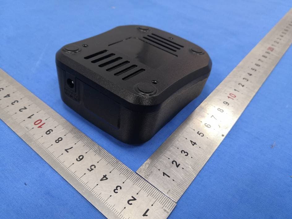
WVTWOUXUN21
Feb 23, 2021TWO-WAY RADIOS
Equipment Class
CSR - Scanning Receiver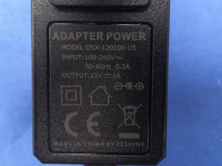
WVTWOUXUN18
Feb 18, 2021TWO-WAY RADIOS
Equipment Class
TNF - Licensed Non-Broadcast Transmitter Held to Face