WWGZ22002.4GHz/10mW TRANSCEIVER MODULE
SUMITOMO PRECISION PRODUCTS CO., LTD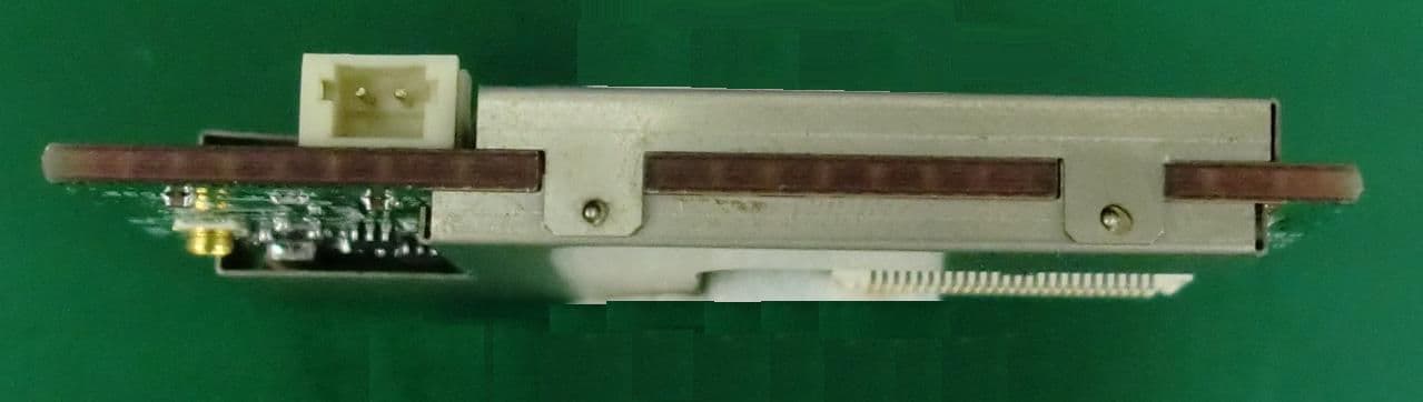
Click to zoom
Application Details
- Equipment Class
- DTS - Digital Transmission System
- Date of Grant
- Jul 31, 2011
- Application Purpose
- Original Equipment
- Date of Application
- Jul 31, 2011
- Equipment Note
- 2.4GHz/10mW TRANSCEIVER MODULE
- Frequency Range
- 2405.00000000 - 2475.00000000
- Country
- Japan
Documents & Files
Document Text
Text extracted from the exhibit documents filed with the FCC. Open a document above to read the original.
Users Manual
©2011 SUMITOMO PRECISION PRODUCTS CO.,LTD. (1/16) [WM-Z2200] High Power RF module Installation manual Sumitomo Precision Products Sumitomo Precision ProductsSumitomo Precision Products Sumitomo Precision Products ©2011 SUMITOMO PRECISION PRODUCTS CO.,LTD. (2/16) Components The components of hardware when the product will be delivered. □ [WM-Z2200] RF module ©2011 SUMITOMO PRECISION PRODUCTS CO.,LTD. (3/16) Contents 1. Product Overview 4 2. General rated value 5 3. Absolute Maximum Ratings 6 4. Recommended Operating Conditions 6 5. Electrical Characteristic 7 6. Electrical Design Information 9 7. Module Exterior Description 11 8. Block Diagram 12 9. Interface Connector Description 13 10. Module Mechanical Drawings 14 11. Installation Instructions 15 12. Production Number Description 16 ©2011 SUMITOMO PRECISION PRODUCTS CO.,LTD. (4/16) 1. Product Overview ■ ■■ ■Features / Overview This product is a 2.4GHz wireless module for data communication used by the transmit power up to 10mW . The following features. 1. PLL synthesizer scheme, a total of 15 channels can be set at 5MHz step 2405MHz to 2475MHz. 2. As a power supply is a supply connector I / F or external AC adapter. 3. The various sensors and external devices connect to the I/O interface. Get the sensor data or it is possible to control the external device. 4. Up to 250kbps data communication is possible. 5. RoHS compliant. ©2011 SUMITOMO PRECISION PRODUCTS CO.,LTD. (5/16) 2. General rated value Table2-1. General rated value Item SPEC Remark Radio Radio Radio Radio Characteristic CharacteristicCharacteristic Characteristic 1 Transmission Half-duplex 2 Modulation Offset-QPSK 3 Data Rate 250 Kbps 4 Frequency Range 2405 MHz~2475 MHz 5MHz step、15ch 5 Sensitivity (PER =1%) < -95 dBm MPU MPUMPU MPU Characteristic CharacteristicCharacteristic Characteristic 1 MCU ATMEL AVR 8bit RISK Core 2 Clock Frequency 8 MHz (FLASH) 128KB (SRAM) 4KB 3 Memory (EEPROM) 4KB 4 A/D converter 10bit、 7ch 5 Analog Comparator 1ch 6 SPI 1ch 7 USART(UART) 2ch 8 I2C 1ch 9 DIO 16ch 10 PWM 2ch Power S Power SPower S Power Supply upplyupply upply 1 Input Voltage DC 2.7V to 3.3V 2 Transmit Current < 100 mA @DC 3.0 V 3 Receiver Current < 80 mA @DC 3.0 V 4 Sleep Current < 1 mA Environmental EnvironmentalEnvironmental Environmental Specifications Specifications Specifications Specifications 1 Operating Temperature -10 deg.C to +70 deg.C 2 Humidity 0 to 90 % R.H. External External External External Interface InterfaceInterface Interface 1 Antenna Connector 20279-001E-01 (I-PEX Coaxial) 50 ohm 2 I/O Connector AXK5F50547YG (Panasonic) 3 PS Connector S2B-ZR-SM4A-TF (JST) Outline information Outline informationOutline information Outline information 1 Dimensions W:50 ×D:25 ×H:7.5 (mm) 2 Weight < 15 g ©2011 SUMITOMO PRECISION PRODUCTS CO.,LTD. (6/16) 3. Absolute Maximum Ratings Table 3-1. Absolute Maximum Ratings Item Units Min. Max. Remark 1 Power Supply V 0 3.6 2 Storage Temperature °C -20 80 4. Recommended Operating Conditions Table4-1. Recommended Operating Conditions Item Units Min. Max. Remark 1 Operating Voltage V 2.85 3.15 2 Ripple Input Level mV p-p - 10 3 Operating Temp. Range °C -10 70 ©2011 SUMITOMO PRECISION PRODUCTS CO.,LTD. (7/16) 5. Electrical Characteristic Table5-1. RF Characteristic Table5-2. I/O DC Characteristic Item Units Min. Max. Remark Digital I/O Voltage Level Input Low Voltage (V IL ) V 0 0.2 x Vcc Input High Voltage (V IH ) V 0.6 x Vcc Vcc Output Low Voltage (V OL ) V - 0.5 I OL =10mA ,Vcc=3V 1 Output High Voltage (V OH ) V 2.2 - I OL =-10mA ,Vcc=3V Two-wire Serial Interface Characteristics Input Low Voltage (V IL ) V 0 0.3 x Vcc Input High Voltage (V IH ) V 0.7 x Vcc Vcc 2 Output Low Voltage (V OL ) V 0 0.4 I OL =3mA Notes 1. Detailed specifications are the property of microcontroller(ATmega128L) data sheet. Item SPEC Remark Transmit Characteristic 1 Output Power +10dBm max. 2 Frequency Tolerance < ±50 ppm 3 ACLR < -25dB 4 OBW < 5MHz (99%OBW) Receiver Characteristic 1 Sensitivity (PER =1%) < -95dBm 2 Spurious Response > 25dB 3 Adjacent Channel Selectivity > 20dB (±5MHz) 4 Co-Channel Selectivity > -6dB 5 Carrier Sense (RSSI) Detectable Level:-77dBm±5dB Link Budget : >90dB ©2011 SUMITOMO PRECISION PRODUCTS CO.,LTD. (8/16) ■ ■■ ■ RF Overview ●RF Band Description, Channels The module has adopted the 2.4GHz band compliant with IEEE802.15.4. (MHz.) CH Lower Freq. Center Freq. Upper Freq. 11 2404 2405 2406 12 2409 2410 2411 13 2414 2415 2416 14 2419 2420 2421 15 2424 2425 2426 16 2429 2430 2431 17 2434 2435 2436 18 2439 2440 2441 19 2444 2445 2446 20 2449 2450 2451 21 2454 2455 2456 22 2459 2460 2461 23 2464 2465 2466 24 2469 2470 2471 25 2474 2475 2476 Fig5-1. IEEE802.15.4(ZigBee) Channels and Frequency Table5-3 IEEE802.15.4 Channel vs Frequency ©2011 SUMITOMO PRECISION PRODUCTS CO.,LTD. (9/16) 6. Electrical Design Information 6.1 Recommended Power Supply Circuit This module is not equipped with a voltage regulator, when the external circuit design, please be sure to configure the voltage regulator. Reference circuit : XC6210 series by TOREX 6.2 Power on status (Reset) The module will begin operating from 100msec after being turned on. T TT To RF module o RF moduleo RF module o RF module input input input input Fig6-1 Reference circuit ON GND Vcc ON GND MCU MCU Reset RF module power-on status 100msec Fig6-2. RF module at power-on sequence Power Supply Power SupplyPower Supply Power Supply (5V) (5V) (5V) (5V) ©2011 SUMITOMO PRECISION PRODUCTS CO.,LTD. (10/16) 6.3 I/O Ports All ports are output from the MCU was set as soon as the module power-on. All I/O pins have protection diodes to both VCC and Ground as indicated in Fig.6-3. 6.4 External Reset An External Reset is generated by a low level on the RESET pin. Reset pulses longer than the minimum pulse width (see Table6-1) will generate a reset, even if the clock is not running. Shorter pulses are not guaranteed to generate a reset. When the applied signal reaches the Reset Threshold Voltage – V RST on its pos…
Text truncated - open the document above for the full version.
Users Manual
©2011 SUMITOMO PRECISION PRODUCTS CO.,LTD. Page 1 2.4GHz/10mW TRANSCEIVER MODULE WM-Z2200 Hardware User’s Manual Features ・ WM-Z2200 is a 2.4 GHz/10mW IEEE 802.15.4, transceiver module designed for wireless sensor measurement system and data link device. ・ The transceiver module includes the direct digital sequence spectrum diffusion baseband modem that offers an effective data rate of 250Kbps. ・ The frequency synthesizer operates for operation frequency range of 2405-2475MHz with 5MHz channel spacing. ・ Frequency stability of 50ppm is determined by a single crystal oscillator (16.000MHz). Benefits ・ Highly reliable even if the RF environment changes. ・ Provides simpler, faster, and easier installation of wireless sensor network system. ・ By the addition of the front end, long-distance communication was enabled. Figure 1. WM-Z2200 ©2011 SUMITOMO PRECISION PRODUCTS CO.,LTD. Page 2 TRANSCEIVER MODULE (type: :: :WM-Z2200) for Wireless Sensor Network system Figure 2. Wireless sensor network system concept Description The transceiver module (WM-Z2200) forms a Wireless Sensor Network system (WSN) with the sensor unit and the equipment control unit, as shown in Fig.2 . WSN utilizes wireless mesh technology. A wireless mesh network consists of a collection of nodes that communicate with each other by ad-hoc routing. A grid-like topology enables the signal to hop among different paths in order to circumvent obstructions as it seeks and ultimately finds its target device. These redundant communication paths enable a very high reliability. Because multiple signal paths exist, the network can adjust to potential communication link disruptions due to changes in the physical environment. Once installed and powered, the transceivers automatically form a mesh network, and the Xmesh's communication is virtually transparent to the system and end user. :Router / Sensor node :Gateway node :Mesh-network line Server PC :USB line ©2011 SUMITOMO PRECISION PRODUCTS CO.,LTD. Page 3 Specifications No. It e m Spec Notes 1 Frequency 2405 to 2475 MHz, 5 MHz channel spacing. 15 selectable channels of operation in the 2.4 GHz ISM band. 2 Modulation O-QPSK Direct Sequence Spread Spectrum radio in accordance with the IEEE 802.15.4 specification 3 Oscillator Frequency Synthesizer 4 Transmit bit rate 250Kbps 5 Antenna Impedance 50ohm unbalanced 6 Antenna type Coaxial connector I-PEX type 7 Receiver type Super heterodyne 8 Operating Temperature -10 to +70°C 9 Dimensions 50mm x 25mm x 7.5mm 10 Power Voltage +2.7 ~ +3.3Vdc Transmission Specifications No. Item Spec Notes 㻝 Frequency error tolerance + /- 50ppm 㻞 Harmonics 20 dB down from the highest emission level Conducted 㻟 Adjacent ch leakage < -25dBm 㻠 Occupied bandwidth < 5MHz(99% OBW) 5Spurious emission 30-88MHz 88-216MHz 216-960MHz Above 960MHz < 100 uV /m < 150 uV/m < 200 uV/m < 500 uV/m Radiated 6 Current dissipation < 100mA Receiver Specifications No. Item Spec Notes 1 Sensitivity (PER=1%) < -95dBm 2 Spurious emission < -47dBm @1GHz and more 3 Spurious Response > 25dB 4 Adjacent channel rejection > 25dB (+ /- 5MHz) 5 Selectivity < -6dB 6 Inter-modulation > 25dB 7 Carrier Sense Level:-77dBm + /- 5dBm Dynamic Range:> 90dB 8 Current dissipation < 80mA ©2011 SUMITOMO PRECISION PRODUCTS CO.,LTD. Page 4 Interface Connector Description Pin. Name I/O Description Pin Name I/O Description 1 GND Ground 26 PE3 I/O GPIO 2 DVDD Power Supply 27 USART0_RXD I USART0 Receive 3 INT7 I/O GPIO 28 USART0_TXD O USART0 Transmit 4 NC Not Connected 29 PC0 I/O GPIO 5 INT5 I/O GPIO 30 PC1 I/O GPIO 6 INT4 I/O GPIO 31 PC2 I/O GPIO 7 NC Not Connected 32 PC3 I/O GPIO 8 LED3 O LED (Yellow) 33 PC4 I/O GPIO 9 LED2 O LED (Green) 34 PC5 I/O GPIO 10 LED1 O LED (Red) 35 PC6 I/O GPIO 11 PG1 I/O GPIO 36 NC Not Connected 12 PG0 I/O GPIO 37 ADC6 I ADC Channel 6 13 PG2 I/O GPIO 38 ADC5 I ADC Channel 5 14 PC7 I/O GPIO 39 ADC4 I ADC Channel 4 15 NC Not Connected 40 ADC3 I ADC Channel 3 16 PDI I Programming Data Input 41 ADC2 I ADC Channel 2 17 PDO O Programming Data Out 42 ADC1 I ADC Channel 1 18 SCK I SPI Serial Clock 43 ADC0 I ADC Channel 0 19 NC Not Connected 44 NC Not Connected 20 NC Not Connected 45 NC Not Connected 21 I2C_CLK O I2C Bus clock 46 NC Not Connected 22 I2C_DATA O I2C Bus data 47 /RSTN I Reset 23 PB4 I/O GPIO 48 PB6 I/O GPIO 24 PB5 I/O GPIO 49 DVDD Power Supply 25 PE2 I/O GPIO 50 GND Ground pin26 pin25 pin1 J1 : Power supply connector [S2B-ZR-SM4A-TF] pin1 Vcc GND J2 : I/O connector [AXK5F50547YG] pin50 J2 : Pin definitions © 2011 SUMITOMO PRECISION PRODUCTS CO.,LTD. Page 5 Block diagram ※ The modular transmitter don't have its power supply regulation. In installing the module, please be sure to configure the voltage regulator. J1 J2 J9 © 2011 SUMITOMO PRECISION PRODUCTS CO.,LTD. Page 6 Dimensional drawing unit : mm ©2011 SUMITOMO PRECISION PRODUCTS CO.,LTD. Page 7 Compliance Statement FCC WARNING : Changes or modifications not expressly approved by the party responsible for compliance could void the user’s authority to operate the equipment. This device complies with Part 15 of the FCC Rules. Operation is subject to the following two Conditions: (1) this device may not cause harmful interference, and (2) this device must accept any interference received, including interference that may cause undesired operation. FCC ID : WWGZ2200 NOTE: This equipment has been tested and found to comply with the limits for a Class B digital device, pursuant to part 15 of the FCC Rules. These limits are designed to provide reasonable protection against harmful interference in a residential installation. This equipment generates uses and can radiate radio frequency energy and, if not installed and used in accordance with the instructions, may cause harmful interference to radio communications. This transmitter must not be co-located or operated in conjunction with any other antenna or transmitter. However, there is no guarantee that interference will not occur in a particular installation. If this equipment does ca…
Text truncated - open the document above for the full version.
Cover Letter(s)
Letter Of Agency Date: July 20, 2011 UL Japan, Inc. 4383-326 Asama-cho, Ise-shi, Mie 516-0021 Japan FCC ID: WWGZ2200 To Whom It May Concern: Please be advised SUMITOMO PRECISION PRODUCTS CO., LTD authorizes Yoshinobu Asai of Application Section, WiSE Japan, UL Verification Service, UL Japan, Inc. to act on our behalf, until otherwise notified, for applications submitted for Federal Communication Commission Radio equipment applications submitted to UL Japan, Inc. We certify that we are not subject to denial of federal benefits, that includes FCC benefits, pursuant to Section 5301 of the Anti-Drug Abuse ACT of 1988, U.S.C. 862. Further, no party, as defined in 47 CFR 1.2002(b), to the application is subject to denial of federal benefits, that includes FCC benefits. The application for the subject equipment has not been submitted to another TCB for certification. Thank you for your attention to this matter. Sincerely, Jun-ya Tada SUMITOMO PRECISION PRODUCTS CO., LTD
Cover Letter(s)
July 28, 2011 FCC ID : WWGZ2200 Model : WM-Z2200 Applicant : SUMITOMO PRECISION PRODUCTS CO., LTD. Request fo Request foRequest fo Request for rr r Limited LimitedLimited Limited Mod ModMod Modular Transmitter Approval ular Transmitter Approvalular Transmitter Approval ular Transmitter Approval This 2.4GHz wireless Module (Model: WM-Z2200) is designed by SUMITOMO PRECISION PRODUCTS CO., LTD. This modular transmitter complies with the modular transmitters basic requirements (Item 1 to 8) in FCC Part 15 Subpart C Section 15.212 as indicated below: [Modular transmitters basic requirements] (1) Have its own RF shielding: This modular transmitter has its own RF shielding. Please refer to the external photo. (2) Have buffered modulation/data inputs: Data input to this modular transmitter is controlled as not generating excessive data speed and abnormal modulation. (3) Have its own power supply regulation: This modular transmitter does not have own power supply regulator. The Sumitomo Precision Products Co., LTD product provides stable voltage (DC5V) constantly to the EUT regardless of input voltage. (4) Comply with the antenna and transmission system requirements of § 15.203, 15.204(b) and 15.204(c): The EUT has a unique coupling/antenna connector(U.FL). This modular transmitter will always be used in the configuration in which it was authorized. (5) Tested in a stand-alone configuration: The modular transmitter has been performed the testing as a stand alone and then confirmed the compliance. Unless the transmitter module will be battery powered, it must comply with the AC line conducted requirements found in FCC § 15.207. AC or DC power lines and data input/output lines connected to the module must not contain ferrites, unless they will be marketed with the module. The length of these lines shall be the length typical of actual use or, if that length is unknown, at least 10 centimeters to insure that there is no coupling between the case of the module and supporting equipment. Any accessories, peripherals, or support equipment connected to the module during testing shall be unmodified and commercially available: This modular transmitter complies with AC line conducted requirements. AC/DC power lines and data input/output lines does not contain ferrites, and the lengths of these lines are typical of actual use. All peripherals used during the testing are unmodified and commercially available. Please refer to the test report. (6) Equipped with either a permanently affixed label or must be capable of electronically displaying its FCC ID: FCC ID is shown on the label and permanently affixed to this modular transmitter. Please refer to the label drawing. If the FCC ID is not visible when the module is installed inside another device, then the outside of the device into which the module is installed must also display a label referring to the enclosed module: If the FCC ID is not visible, FCC ID will also be displayed on the host device. Please refer to the user manual. (7) Comply with any specific rules or operating requirements that ordinarily apply to a complete transmitter and the manufacturer must provide adequate instructions along with the module to explain any such requirements: The necessary explanation to be complied with this requirement is contained in the manual. Please refer to the user manual. (8) Comply with any applicable RF exposure requirements in its final configuration: The modular transmitter complies with FCC radiation exposure requirement. Please refer to the RF Exposure/SAR Statement. Jun-ya Tada SUMITOMO PRECISION PRODUCTS CO., LTD
Cover Letter(s)
Request for Confidentiality Date: July 20, 2011 UL Japan, Inc. 4383-326 Asama-cho, Ise-shi, Mie 516-0021 Japan RE: Certification Application FCC ID: WWGZ2200 Please be advised that the following information is to be held confidential on behalf of SUMITOMO PRECISION PRODUCTS CO., LTD, referring to the FCC rules 0.457 and 0.459: Schematics Diagram Block Diagram Parts List Theory of Operation The application contains technical information which SUMITOMO PRECISION PRODUCTS CO., LTD deems to be trade secrets and proprietary. If made public, the information might be used to the disadvantage of the applicant in the market place. Thank you for your attention to this matter. Sincerely, Jun-ya Tada SUMITOMO PRECISION PRODUCTS CO., LTD
External Photos
© 2011 Sumitomo Precision Products Co., LTD. Module ModuleModule Module E EE Exterior xteriorxterior xterior P PP Photograph hotographhotograph hotograph Fig1. Top Side Fig2. Bottom Side Sumitomo Precision Products Co., LTD. Model:WM-Z2200 FCC ID:WWGZ2200 © 2011 Sumitomo Precision Products Co., LTD. Fig3. Side view (Front side) Fig4. Side view (Right side) Antenna Photo
ID Label/Location Info
© 2011 Sumitomo Precision Products Co., LTD. Label LabelLabel Label Information InformationInformation Information Fig.1. Label design Fig2. Label Location (Top View) Sumitomo Precision Products Co., LTD. Model:WM-Z2200 FCC ID:WWGZ2200
Internal Photos
© 2011 Sumitomo Precision Products Co., LTD. Module ModuleModule Module Internal InternalInternal Internal P PP Photograph hotographhotograph hotograph Fig1. Top Side Fig2. Bottom Side Sumitomo Precision Products Co., LTD. Model:WM-Z2200 FCC ID:WWGZ2200
RF Exposure Info
UL Japan, Inc. Shonan EMC Lab. 1-22-3 Megumigaoka, Hiratsuka-shi, Kanagawa-ken, 259-1220 JAPAN Telephone : +81 463 50 6400 Facsimile : +81 463 50 6401 A p p lic a n t: S U M IT IO M O P R E C IS IO N P R O D U C T S C O .,L T D T y p e o f E q u ip m e n t: 2 .4 G H z/1 0 m W T R A N S C E IV E R M O D U L E M o d e l N o . : W M - Z 2 2 0 0 F C C ID: W W G Z 2 2 0 0 SUM ITIOM O PRECISION PRODUCTS CO.,LTD declares that M odel : 2.4GH z/10m W TRAN SCEIVER M ODULE com plies w ith FCC radiation exposure requirem ent specified in the FCC Rules 2.1093. The “W M-Z2200“ has 10.72 m W of conducted Peak Output pow er and 16.98 m W of EIRP. This kind of equipm ent is below 60/frequency[MH z] W (TCB Exclusion List) so that SAR testing is excluded. The Follow ing calculation is the reference data for 20cm distance. R F E xp o su re C a lc u la tio n s: T he fo llo w in g info rm a t io n p r o vid e s t he m inim u m se p ara t io n d ist a nc e fo r t he hig he st g a in a nt e nna p ro vid e d w it h t h e “W M -Z 2 2 0 0 “ a s ca lc u la t e d fr o m F C C O E T B u lle t in 6 5 A p p e nd ix A , T a ble ( B ) L im it s fo r G e ne ra l P o p u lat io n / U nc o nt ro lle d E xp o su r e. T his ca lc u la t io n is ba se d o n t he hig he st E I R P p o ssible fr o m t he syst em , c o nsid e r ing m a xim u m p o w e r a nd ant enn a g a in, a nd c o nsid e ring a 1 .0 m W /c m ^2 u nco nt r o lle d e xp o su r e lim it . T he F r iis fo r m u la u se d w a s: S = (P * G ) / ( 4 * π * r 2 ) W h e re P = 1 0 .7 2m W (M a xim u m p ea k o u tp u t p o w e r) G = 1 .5 8N u m eric a l A n t en n a g a in ; eq u a l t o2 .0 0d B i r =2 0 .0 c m F o r: W M -Z 2 2 0 0S = 0 .0 0 3 3 8 m W /c m 2 N o . : 3 1 F E 0 0 7 8 -S H -0 1 -A R F E x p o s u r e / S A R S ta te m e n t
Test Report
Test report No. : 31FE0078-SH-01-A-R1 Page : 2 of 41 Issued date : August 1, 2011 FCC ID : WWGZ2200 UL Japan, Inc. Shonan EMC Lab. 1-22-3 Megumigaoka, Hiratsuka-shi, Kanagawa-ken, 259-1220 JAPAN Telephone : +81 463 50 6400 Facsimile : +81 463 50 6401 Contents Page SECTION 1: Customer information ..................................................................................... 3 SECTION 2: Equipment under test (E.U.T.) ....................................................................... 3 SECTION 3: Test specification, procedures & results ......................................................... 4 SECTION 4: Operation of E.U.T. during testing ................................................................. 7 SECTION 5: Conducted emission ......................................................................................... 8 SECTION 6: 6dB bandwidth & Occupied bandwidth (99%) ............................................. 8 SECTION 7: Maximum peak output power ......................................................................... 9 SECTION 8: Spurious emission (Antenna port conducted) ................................................ 9 SECTION 9: Radiated emission .......................................................................................... 10 SECTION 10: Peak Power density ...................................................................................... 11 Contents of appendixes ......................................................................................................... 12 APPENDIX 1: Photographs of test setup ............................................................................ 13 APPENDIX 2: Test data ...................................................................................................... 17 APPENDIX 3: Test instruments .......................................................................................... 41 Test report No. : 31FE0078-SH-01-A-R1 Page : 3 of 41 Issued date : August 1, 2011 FCC ID : WWGZ2200 UL Japan, Inc. Shonan EMC Lab. 1-22-3 Megumigaoka, Hiratsuka-shi, Kanagawa-ken, 259-1220 JAPAN Telephone : +81 463 50 6400 Facsimile : +81 463 50 6401 SECTION 1: Customer information Company Name : SUMITOMO PRECISION PRODUCTS CO., LTD. Brand or Trade name : SPP Address : 1-10, Fuso-cho, Amagasaki, Hyogo, 660-0891 Japan Telephone Number : +81-6-6489-8264 Facsimile Number : +81-6-6489-5910 Contact Person : Junya Tada SECTION 2: Equipment under test (E.U.T.) 2.1 Identification of E.U.T. Type of Equipment : 2.4GHz/10mW TRANSCEIVER MODULE Model Number : WM-Z2200 Serial Number : 1105500002 Rating : DC5V Country of Mass-production : Japan Condition of EUT : Production prototype (Not for Sale: This sample is equivalent to mass-produced items.) Receipt Date of Sample : March 1, 2011 Modification of EUT : No modification by the test lab. 2.2 Product description Model: WM-Z2200 (referred to as the EUT in this report) is a 2.4GHz/10mW TRANSCEIVER MODULE. Clock frequency(ies) in the system : 7.3728MHz Equipment type : Transceiver Frequency of operation : 2405-2475MHz Bandwidth & channel spacing : 5MHz & 5MHz Type of modulation : Offset- QPSK Antenna type : Dipole Antenna Antenna gain : 2.0dBi(W1030), 2.1dBi(ANTB18-135A0), 1.8dBi(ANTB18-143A0C0), 1.8dBi(ANTB18-143B0C0), 1.8dBi (ANTB18-152A0) *1) Antenna connector type : I-PEX(U.FL) ITU code : G1D Operation temperature range : -10 to 70 deg.C. *1) The antennas W1030 and ANTB18-135A0 were tested as representatives. ANTB18-135A0 was selected since it has the highest antenna gain in 4 antennas (ANTB18-**). FCC Part15.31 (e) The Sumitomo Precision Products CO., LTD. product provides stable voltage (DC5V) constantly to the EUT regardless of input voltage. Therefore, the EUT complies with the requirement. FCC Part15.203 The EUT has a unique coupling/antenna connector (U.FL). Therefore the equipment complies with the requirement of 15.203. Test report No. : 31FE0078-SH-01-A-R1 Page : 4 of 41 Issued date : August 1, 2011 FCC ID : WWGZ2200 UL Japan, Inc. Shonan EMC Lab. 1-22-3 Megumigaoka, Hiratsuka-shi, Kanagawa-ken, 259-1220 JAPAN Telephone : +81 463 50 6400 Facsimile : +81 463 50 6401 SECTION 3: Test specification, procedures & results 3.1 Test specification Test specification : FCC Part 15 Subpart C: 2010, final revised on December 6, 2010 and effective January 5, 2011 Title : FCC 47CFR Part15 Radio Frequency Device Subpart C Intentional Radiators Section 15.207 Conducted limits Section 15.209 Radiated emission limits, general requirements Section 15.247 Operation within the bands 902-928MHz, 2400-2483.5MHz, and 5725-5850MHz The EUT complies with FCC Part 15 Subpart B: 2010 although the test has been performed on the host device. Refer to the test report: 31FE0078-SH-01-B. 3.2 Procedures & Results Item Test Procedure Specification Remarks DeviationWorst Margin Results Conducted emission ANSI C63.4:2003 7. AC powerline conducted emission measurements FCC 15.207 - N/A 11.3dB Freq.: 0.31310MHz Phase: N Detection: Average Mode: Tx 11ch 2405MHz and Freq.: 0.30295MHz Phase: N Detection: Average Mode: Tx 18ch 2440MHz (Antenna:ANTB18-135A0) Complied 6dB bandwidth "Guidance on Measurement for Digital Transmission Systems Section 15.247" & ANSI C63.4:2003 13. Measurement of intentional radiators FCC 15.247 (a)(2) & 15.209 ConductedN/A See data Complied Maximum peak output power "Guidance on Measurement for Digital Transmission Systems Section 15.247" & ANSI C63.4:2003 13. Measurement of intentional radiators FCC 15.247 (b)(3) & 15.209 ConductedN/A Complied Spurious emission & Restricted band edges "Guidance on Measurement for Digital Transmission Systems Section 15.247" & ANSI C63.4:2003 13. Measurement of intentional radiators FCC 15.109, 15.247 (d) & 15.209 Conducted / Radiated N/A 3.1dB Freq.: 2549.164 MHz Polarization: Horizontal Detection: Average Mode: Tx 11ch 2405MHz (Antenna:ANTB18-135A0) Complied Power density "Guidance on Measurement for Digital Transmission Systems Section 15.247" & A…
Text truncated - open the document above for the full version.
Test Report
DATA OF CONDUCTED EMISSION TEST UL Japan,Inc. Shonan EMC Lab. No.2 Shielded Room Date : 2011/07/01 Company: SUMITOMO PRECISION PRODUCTS CO.,LTD Mode: Transmitting(11ch: 2405MHz) Kind of E.U.T.: 2.4GHz/10mW TRANSCEIVER MODULE Report No. : 31FE0078-SH-01-A-R1 Model No.: WM-Z2200Power: AC120V/60Hz Serial No.: 1105500002Temp./Humi.: 27°C / 63% Remarks:Antenna:W1030 Limit1 : FCC 15C(15.207) QP Limit2 : FCC 15C(15.207) AVEngineer:: Hikaru Shirasawa Calculation:Result[dBuV]=Reading[dBuV]+C.Fac(ISN+Cable)[dB] LISN:SLS-03 Limit1(QP) Limit2(AV) N(PK) N(QP/AV) L1(PK) L1(QP/AV) Frequency [MHz] RFI Voltage [dBuV] .1530 .2.3.5.7123571020 0 10 20 30 40 50 60 70 80 90 100 No. Freq. ReadingReading C.Fac ResultsResultsLimitLimitMarginMargin PhaseCommentNo. Freq. <QP><AV> C.Fac <QP><AV><QP><AV><QP><AV>PhaseCommentNo. [MHz][dBuV][dBuV][dB][dBuV][dBuV][dBuV][dBuV][dB][dB] PhaseComment 10.2224027.3---12.639.9---62.752.722.8---N 20.3391730.523.112.743.235.859.249.216.013.4N 30.5001423.1---12.735.8---56.046.020.2---N 40.6006822.6---12.735.3---56.046.020.7---N 51.0329722.3---12.835.1---56.046.020.9---N 62.2195022.1---12.834.9---56.046.021.1---N 70.2201027.7---12.640.3---62.852.822.5---L1 80.3381230.317.712.743.030.459.249.216.218.8L1 90.5008219.5---12.732.2---56.046.023.8---L1 100.6000120.6---12.733.3---56.046.022.7---L1 111.0362318.1---12.830.9---56.046.025.1---L1 122.2138520.2---12.833.0---56.046.023.0---L1 DATA OF CONDUCTED EMISSION TEST UL Japan,Inc. Shonan EMC Lab. No.2 Shielded Room Date : 2011/07/01 Company: SUMITOMO PRECISION PRODUCTS CO.,LTD Mode :Transmitting(18ch: 2440MHz) Kind of E.U.T.: 2.4GHz/10mW TRANSCEIVER MODULE Report No. : 31FE0078-SH-01-A-R1 Model No.: WM-Z2200Power: AC120V/60Hz Serial No.: 1105500002Temp./Humi.: 27°C / 63% Remarks:Antenna:W1030 Limit1 : FCC 15C(15.207) QP Limit2 : FCC 15C(15.207) AVEngineer:: Hikaru Shirasawa Calculation:Result[dBuV]=Reading[dBuV]+C.Fac(ISN+Cable)[dB] LISN:SLS-03 Limit1(QP) Limit2(AV) N(PK) N(QP/AV) L1(PK) L1(QP/AV) Frequency [MHz] RFI Voltage [dBuV] .1530 .2.3.5.7123571020 0 10 20 30 40 50 60 70 80 90 100 No. Freq. ReadingReading C.Fac ResultsResultsLimitLimitMarginMargin PhaseCommentNo. Freq. <QP><AV> C.Fac <QP><AV><QP><AV><QP><AV>PhaseCommentNo. [MHz][dBuV][dBuV][dB][dBuV][dBuV][dBuV][dBuV][dB][dB] PhaseComment 10.2206026.7---12.639.3---62.752.723.4---N 20.2814227.4---12.740.1---60.750.720.6---N 30.3354029.822.212.742.534.959.349.316.814.4N 40.4971024.618.112.737.330.856.046.018.715.2N 50.5581921.4---12.734.1---56.046.021.9---N 60.6024724.2---12.736.9---56.046.019.1---N 70.6612024.2---12.736.9---56.046.019.1---N 80.7120821.4---12.734.1---56.046.021.9---N 92.1212019.5---12.832.3---56.046.023.7---N 100.2198927.6---12.640.2---62.852.822.6---L1 110.2809027.3---12.740.0---60.750.720.7---L1 120.3358529.617.012.742.329.759.349.317.019.6L1 130.4973521.413.412.734.126.156.046.021.919.9L1 140.5564518.1---12.730.8---56.046.025.2---L1 150.6037620.8---12.733.5---56.046.022.5---L1 160.6617120.0---12.732.7---56.046.023.3---L1 170.7108418.3---12.731.0---56.046.025.0---L1 182.1659019.7---12.832.5---56.046.023.5---L1 DATA OF CONDUCTED EMISSION TEST UL Japan,Inc. Shonan EMC Lab. No.2 Shielded Room Date : 2011/07/01 Company: SUMITOMO PRECISION PRODUCTS CO.,LTD Mode: Transmitting(25ch: 2475MHz) Kind of E.U.T.: 2.4GHz/10mW TRANSCEIVER MODULE Report No. : 31FE0078-SH-01-A-R1 Model No.: WM-Z2200Power: AC120V/60Hz Serial No.: 1105500002Temp./Humi.: 27°C / 63% Remarks:Antenna:W1030 Limit1 : FCC 15C(15.207) QP Limit2 : FCC 15C(15.207) AVEngineer:: Hikaru Shirasawa Calculation:Result[dBuV]=Reading[dBuV]+C.Fac(ISN+Cable)[dB] LISN:SLS-03 Limit1(QP) Limit2(AV) N(PK) N(QP/AV) L1(PK) L1(QP/AV) Frequency [MHz] RFI Voltage [dBuV] .1530 .2.3.5.7123571020 0 10 20 30 40 50 60 70 80 90 100 No. Freq. ReadingReading C.Fac ResultsResultsLimitLimitMarginMargin PhaseCommentNo. Freq. <QP><AV> C.Fac <QP><AV><QP><AV><QP><AV>PhaseCommentNo. [MHz][dBuV][dBuV][dB][dBuV][dBuV][dBuV][dBuV][dB][dB] PhaseComment 10.2209026.5---12.639.1---62.752.723.6---N 20.2796628.321.912.…
Text truncated - open the document above for the full version.
Contact Information
Applicant
Jun-ya Tada
Technical Contact
UL Japan, Inc.Ichiro Isozaki
[email protected]81-463-50-6400
1-22-3, Megumigaoka, Hiratsuka-shi · Kanagawa-ken · Japan
Test Firm
UL Japan, Inc. Shonan EMC EMC Lab.Tetsuya Hashimoto
Technical Specifications
| # | Rule Parts | Frequency Range | Power Output |
|---|---|---|---|
| 1 | 15C | 2.40 GHz - 2.48 GHz | 10.70 mW |
Other Applications from SUMITOMO PRECISION PRODUCTS CO., LTD
WWGZ3001
Oct 28, 2013920MHz/20mW TRANSCEIVER MODULE
Equipment Class
DSS - Part 15 Spread Spectrum Transmitter
WWGZ2210
Apr 05, 20122.4GHz/10mW TRANSCEIVER MODULE
Equipment Class
DTS - Digital Transmission System