WWGZ22102.4GHz/10mW TRANSCEIVER MODULE
SUMITOMO PRECISION PRODUCTS CO., LTD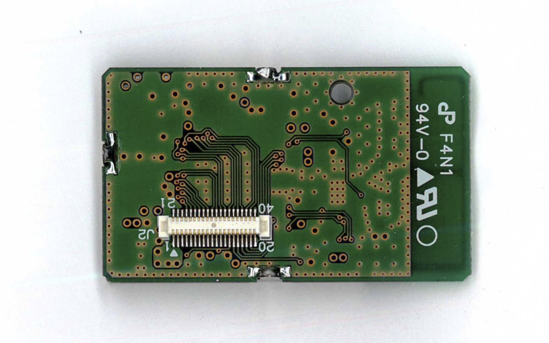
Click to zoom
Application Details
- Equipment Class
- DTS - Digital Transmission System
- Date of Grant
- Apr 05, 2012
- Application Purpose
- Original Equipment
- Date of Application
- Apr 05, 2012
- Equipment Note
- 2.4GHz/10mW TRANSCEIVER MODULE
- Frequency Range
- 2405.00000000 - 2475.00000000
- Country
- Japan
Documents & Files
Document Text
Text extracted from the exhibit documents filed with the FCC. Open a document above to read the original.
Users Manual
©2012 SUMITOMO PRECISION PRODUCTS CO.,LTD. Page 1 2.4GHz/10mW TRANSCEIVER MODULE WM-Z2210 Hardware User’s Manual Features ・ WM-Z2210 is a 2.4 GHz/10mW IEEE 802.15.4, transceiver module designed for wireless sensor measurement system and data link device. ・ The transceiver module includes the direct digital sequence spectrum diffusion baseband modem that offers an effective data rate of 250Kbps. ・ The frequency synthesizer operates for operation frequency range of 2405-2475MHz with 5MHz channel spacing. ・ Frequency stability of 50ppm is determined by a single crystal oscillator (16.000MHz). Benefits ・ Highly reliable even if the RF environment changes. ・ Provides simpler, faster, and easier installation of wireless sensor network system. ・ By the addition of the front end, long-distance communication was enabled. Figure 1. WM-Z2210 ©2012 SUMITOMO PRECISION PRODUCTS CO.,LTD. Page 2 TRANSCEIVER MODULE (type: :: :WM-Z2210) for Wireless Sensor Network system Figure 2. Wireless sensor network system concept Description The transceiver module (WM-Z2210) forms a Wireless Sensor Network system (WSN) with the sensor unit and the equipment control unit, as shown in Fig.2 . WSN utilizes wireless mesh technology. A wireless mesh network consists of a collection of nodes that communicate with each other by ad-hoc routing. A grid-like topology enables the signal to hop among different paths in order to circumvent obstructions as it seeks and ultimately finds its target device. These redundant communication paths enable a very high reliability. Because multiple signal paths exist, the network can adjust to potential communication link disruptions due to changes in the physical environment. Once installed and powered, the transceivers automatically form a mesh network, and the Xmesh's communication is virtually transparent to the system and end user. :Router / Sensor node :Gateway node :Mesh-network line Server PC :USB line ©2012 SUMITOMO PRECISION PRODUCTS CO.,LTD. Page 3 Specifications No. Item Spec Notes 1 Frequency 2405 to 2475 MHz, 5 MHz channel spacing. 15 selectable channels of operation in the 2.4 GHz ISM band. 2 Modulation O-QPSK Direct Sequence Spread Spectrum radio in accordance with the IEEE 802.15.4 specification 3 Oscillator Frequency Synthesizer 4 Transmit bit rate 250Kbps 5 Antenna Impedance 50ohm unbalanced 6 Antenna type Coaxial connector I-PEX type 7 Receiver type Super heterodyne 8 Operating Temperature -30 to +75°C 9 Dimensions 25mm x 43mm x 4.5mm 10 Power Voltage +2.7 ~ +3.6Vdc Transmission Specifications No. Item Spec Notes 1 RF Power 10 mW 2 Frequency error tolerance + /- 50ppm 3 Harmonics 20 dB down from the highest emission level Conducted 4 Adjacent ch leakage < -25dBm 5 Occupied bandwidth < 5MHz(99% OBW) 6 Spurious emission 30-88MHz 88-216MHz 216-960MHz Above 960MHz < 100 uV/m < 150 uV/m < 200 uV/m < 500 uV/m Radiated 7 Current dissipation < 70mA Receiver Specifications No. Item Spec Notes 1 Sensitivity (PER=1%) < -95dBm 2 Spurious emission < -47dBm @1GHz and more 3 Spurious Response > 25dB 4 Adjacent channel rejection > 25dB (+ /- 5MHz) 5 Selectivity < -6dB 6 Inter-modulation > 25dB 7 Current dissipation < 50mA ©2012 SUMITOMO PRECISION PRODUCTS CO.,LTD. Page 4 Interface Connector Description © 2012 SUMITOMO PRECISION PRODUCTS CO.,LTD. Page 5 Block diagram © 2012 SUMITOMO PRECISION PRODUCTS CO.,LTD. Page 6 Dimensional drawing ©2012 SUMITOMO PRECISION PRODUCTS CO.,LTD. Page 7 Compliance Statement FCC CAUTION : Changes or modifications not expressly approved by the party responsible for compliance could void the user’s authority to operate the equipment. This device complies with Part 15 of the FCC Rules. Operation is subject to the following two Conditions: (1) this device may not cause harmful interference, and (2) this device must accept any interference received, including interference that may cause undesired operation. FCC ID : WWGZ2210 CAUTION: Radio Frequency Radiation Exposure This equipment complies with FCC radiation exposure limits set forth for an uncontrolled environment and meets the FCC radio frequency (RF) Exposure Guidelines in Supplement C to OET65. This equipment has very low levels of RF energy that it deemed to comply without maximum permissive exposure evaluation (MPE). But it is desirable that it should be installed and operated keeping the radiator at least 20cm or more away from person’s body (excluding extremities: hands, wrists, feet and ankles). Co-location: This transmitter must not be co-located or operated in conjunction with any other antenna or transmitter. Products equipped with this device, must indicate the following contents on the label or the Chassis : - “Contains Transmitter Module FCC ID: WWGZ2210 ” or - “Contains FCC ID: WWGZ2210 ” Manufactured by : Sumitomo Precision Products For Sales and Support , contact : Crossbow Japan, Ltd. Sumitomo Precision Products Bldg. 1-10, Fuso-cho, Amagasaki, Hyogo 660-0891 Japan Phone: 81-6-6489-5922 Fax: 81-6-6489-5902 E-mail: [email protected]
Cover Letter(s)
Letter Of Agency Date: March 27, 2012 UL Japan, Inc. 4383-326 Asama-cho, Ise-shi, Mie 516-0021 Japan FCC ID: WWGZ2210 To Whom It May Concern: Please be advised SUMITOMO PRECISION PRODUCTS CO., LTD. authorizes Yoshinobu Asai of Application Section, WiSE Japan, UL Verification Service, UL Japan, Inc. to act on our behalf, until otherwise notified, for applications submitted for Federal Communication Commission Radio equipment applications submitted to UL Japan, Inc. We certify that we are not subject to denial of federal benefits, that includes FCC benefits, pursuant to Section 5301 of the Anti-Drug Abuse ACT of 1988, U.S.C. 862. Further, no party, as defined in 47 CFR 1.2002(b), to the application is subject to denial of federal benefits, that includes FCC benefits. The application for the subject equipment has not been submitted to another TCB for certification. Thank you for your attention to this matter. Sincerely, Jun-ya Tada Assistant Manager SUMITOMO PRECISION PRODUCTS CO., LTD.
Cover Letter(s)
April 4, 2012 FCC ID : WWGZ2210 Model : WM-Z2210 Applicant : SUMITOMO PRECISION PRODUCTS CO., LTD Request for Modular Transmitter Approval This Zigbee Module (Model: WM-Z2210) is designed by SUMITOMO PRECISION PRODUCTS CO., LTD. This modular transmitter complies with the modular transmitters basic requirements (Item 1 to 8) in FCC Part 15 Subpart C Section 15.212 as indicated below: [Modular transmitters basic requirements] (1) Have its own RF shielding: This modular transmitter has its own RF shielding. Please refer to the external photo. (2) Have buffered modulation/data inputs: Data input to this modular transmitter is controlled as not generating excessive data speed and abnormal modulation. (3) Have its own power supply regulation: This modular transmitter has own power supply regulator. Please refer to the block diagram / schematics. (4) Comply with the antenna and transmission system requirements of § 15.203, 15.204(b) and 15.204(c): Antenna is permanently attached to the modular transmitter by solder. / This module has a unique antenna coupler, U-FL. This modular transmitter will always be used in the configuration in which it was authorized. (5) Tested in a stand-alone configuration: The modular transmitter has been performed the testing as a stand alone and then confirmed the compliance. Unless the transmitter module will be battery powered, it must comply with the AC line conducted requirements found in FCC § 15.207. AC or DC power lines and data input/output lines connected to the module must not contain ferrites, unless they will be marketed with the module. The length of these lines shall be the length typical of actual use or, if that length is unknown, at least 10 centimeters to insure that there is no coupling between the case of the module and supporting equipment. Any accessories, peripherals, or support equipment connected to the module during testing shall be unmodified and commercially available: This modular transmitter complies with AC line conducted requirements. AC/DC power lines and data input/output lines does not contain ferrites, and the lengths of these lines are typical of actual use. All peripherals used during the testing are unmodified and commercially available. Please refer to the test report. (6) Equipped with either a permanently affixed label or must be capable of electronically displaying its FCC ID: FCC ID is shown on the label and permanently affixed to this modular transmitter. Please refer to the label drawing. If the FCC ID is not visible when the module is installed inside another device, then the outside of the device into which the module is installed must also display a label referring to the enclosed module: If the FCC ID is not visible, FCC ID will also be displayed on the host device. Please refer to the installation manual. (7) Comply with any specific rules or operating requirements that ordinarily apply to a complete transmitter and the manufacturer must provide adequate instructions along with the module to explain any such requirements: The necessary explanation to be complied with this requirement is contained in the manual. Please refer to the installation manual. (8) Comply with any applicable RF exposure requirements in its final configuration: The modular transmitter complies with FCC radiation exposure requirement. Please refer to the RF Exposure/SAR Statement. Jun-ya Tada Assistant Manager SUMITOMO PRECISION PRODUCTS CO., LTD
Cover Letter(s)
Request for Short-Term Confidentiality April 4, 2012 UL Japan, Inc. 4383-326 Asama-cho, Ise-shi, Mie 516-0021 Japan RE : Certification Application FCC ID : WWGZ2210 Please be advised that the following information is to be held in confidence for 180 days from the date of the Grant of Equipment Authorization and behalf of, SUMITOMO PRECISION PRODUCTS CO., LTD., referring to the FCC rules 0.457 and 0.459: External Photos Internal Photos Test Setup Photos User Manual The application contains technical information, which SUMITOMO PRECISION PRODUCTS CO., LTD. deems to be trade secrets and proprietary. If made public, the information might be used to the disadvantage of the applicant in the market place. Thank you for your attention to this matter. Sincerely, ____________________________________ Jun-ya Tada Assistant Manager SUMITOMO PRECISION PRODUCTS CO., LTD.
Cover Letter(s)
Request for Confidentiality Date: April 5, 2012 UL Japan, Inc. 4383-326 Asama-cho, Ise-shi, Mie 516-0021 Japan RE: Certification Application FCC ID: WWGZ2210 Please be advised that the following information is to be held confidential on behalf of SUMITOMO PRECISION PRODUCTS CO., LTD., referring to the FCC rules 0.457 and 0.459: Schematics Diagram Block Diagram Theory of Operation The application contains technical information which SUMITOMO PRECISION PRODUCTS CO., LTD. deems to be trade secrets and proprietary. If made public, the information might be used to the disadvantage of the applicant in the market place. Thank you for your attention to this matter. Sincerely, Jun-ya Tada Assistant Manager SUMITOMO PRECISION PRODUCTS CO., LTD.
External Photos
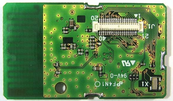
© 2012 Sumitomo Precision Products Co., LTD. Sumitomo Precision Products Co., LTD. Model : WM-Z2210 FCC ID : WWGZ2210 Fig.1 Top Side Module Exterior Photograph Fig.2 Bottom Side © 2012 Sumitomo Precision Products Co., LTD. Sumitomo Precision Products Co., LTD. Model : WM-Z2210 FCC ID : WWGZ2210 Fig.3 Side view Fig.4 Side view Fig.5 Side view Fig.6 Side view
External Photos
Antenna Photograph Integrated Antenna ANTB18-187A0 ANTB18-135A0 W1049B W1049B030 W1030W
ID Label/Location Info
© 2012 Sumitomo Precision Products Co., LTD. Sumitomo Precision Products Co., LTD. Model : WM-Z2210 FCC ID : WWGZ2210 Fig.1 Label design Label Information Fig.2 Label Location(Top View) ○○△△□ ××××× (������)
Internal Photos
Sumitomo Precision Products Co., LTD. Model : WM-Z2210 FCC ID : WWGZ2210 © 2012 Sumitomo Precision Products Co., LTD. Fig.1 Top Side Module Internal Photograph Fig.2 Bottom Side
RF Exposure Info
UL Japan, Inc. Head Office EMC Lab 4383-326 Asama-cho, Ise-shi, Mie 516-0021 Japan T:: +81.596.24.8116 / F:: +81.596.24.8124 / W:: ul.com/jp April 4, 2012 UL Japan, Inc. 4383-326 Asama-cho, Ise-shi, Mie 516-0021 Japan FCC ID: WWGZ2210 To whom it may concern, We, UL Japan, Inc, hereby declare that 2.4GHz/10mW TRANSCEIVER MODULE, model: WM-Z2210 (FCC ID: WWGZ2210) of SUMITOMO PRECISION PRODUCTS CO., LTD. is exempt from RF exposure SAR evaluation as its output power meets the exclusion limits stated in FCC Part 2 §2.1093 and FCC radio frequency (RF) Exposure Guidelines in Supplement C to OET65. Thank you for your attention to this matter. Sincerely, Masanori Nishiyama Leader of Head Office EMC Lab. WiSE Japan UL Verification Service UL Japan, Inc.
Test Report
Test report No. : 32CE0103-HO-01-R1 Page : 2 of 49 Issued date : April 4, 2012 Revised date : April 5, 2012 FCC ID : WWGZ2210 UL Japan, Inc. Head Office EMC Lab. 4383-326 Asama-cho, Ise-shi, Mie-ken 516-0021 JAPAN Telephone : +81 596 24 8116 Facsimile : +81 596 24 8124 CONTENTS PAGE SECTION 1: Customer information ......................................................................................................... 3 SECTION 2: Equipment under test (E.U.T.) ........................................................................................... 3 SECTION 3: Test specification, procedures & results ............................................................................ 4 SECTION 4: Operation of E.U.T. during testing .................................................................................... 7 SECTION 5: Conducted Emission ............................................................................................................ 9 SECTION 6: Radiated Spurious Emission ............................................................................................ 10 SECTION 7: Antenna Terminal Conducted Tests ................................................................................ 11 APPENDIX 1: Data of EMI test .............................................................................................................. 11 Conducted Emission ......................................................................................................................... 12 6dB Bandwidth ................................................................................................................................. 18 Maximum Peak Output Power .......................................................................................................... 20 Radiated Spurious Emission ............................................................................................................. 21 Duty Cycle ........................................................................................................................................ 30 Conducted Spurious Emission .......................................................................................................... 32 Conducted Emission Band Edge compliance ................................................................................... 38 Power Density ................................................................................................................................... 39 99%Occupied Bandwidth ................................................................................................................. 41 APPENDIX 2: Test instruments ............................................................................................................. 42 APPENDIX 3: Duty cycle specification .................................................................................................. 44 APPENDIX 4: Photographs of test setup ............................................................................................... 45 Conducted Emission ......................................................................................................................... 45 Radiated Spurious Emission ............................................................................................................. 46 Test report No. : 32CE0103-HO-01-R1 Page : 3 of 49 Issued date : April 4, 2012 Revised date : April 5, 2012 FCC ID : WWGZ2210 UL Japan, Inc. Head Office EMC Lab. 4383-326 Asama-cho, Ise-shi, Mie-ken 516-0021 JAPAN Telephone : +81 596 24 8116 Facsimile : +81 596 24 8124 SECTION 1: Customer information Company Name : SUMITOMO PRECISION PRODUCTS CO., LTD. Address : 1-10, FUSO-CHO, AMAGASAKI, HYOGO, 660-0891 JAPAN Telephone Number : +81-6-6489-8264 Facsimile Number : +81-6-6489-5910 Contact Person : Junya Tada SECTION 2: Equipment under test (E.U.T.) 2.1 Identification of E.U.T. Type of Equipment : 2.4GHz/10mW TRANSCEIVER MODULE Model No. : WM-Z2210 Serial No. : Refer to Section 4, Clause 4.2 Receipt Date of Sample : March 12, 2012 Country of Mass-production : Japan Condition of EUT : Production prototype (Not for Sale: This sample is equivalent to mass-produced items.) Modification of EUT : No Modification by the test lab 2.2 Product Description General Specification Clock frequency(ies) in the system : 14.7456MHz Radio Specification Radio Type : Transceiver Frequency of Operation : 2405-2475MHz Modulation : Offset QPSK Power Supply : DC 2.7-3.6V Type of Antenna : Dipole antenna Option (External type): Antenna2 to 6 PCB trace antenna (Inverted F type): Antenna1 Antenna Information Antenna1 Antenna2 Antenna3 Antenna4 Antenna5 Antenna6 Model No. - ANTB18- 187A0 ANTB18- 135A0 W1049B W1049B030 W1030W Frequency Range 2400~2500 2400~2500 2400~2500 2400~2500 2400~2500 2400~2500 Impedance 50Ω 50Ω 50Ω 50Ω 50Ω 50Ω Antenna Type Inverted F 1/2λDipole 1/2λDipole 1/4λDipole 1/4λDipole 1/4λDipole Antenna Gain 2.0dBi(Max) 2.0dBi (Max) 1.0dBi (Min) 2.0dBi (nominal) 2.0dBi (MAX) 2.0dBi (nominal) Size 25.0mmx7.5mm φ7.8x82.8mmφ7.8x82.8mmφ7.8x82.5mmφ7.8x82.5mm φ9x82.5mm *Test was performed with Antenna1, Antenna2, and Antenna6 as representative. Antenna2 was chosen as a representatvie 1/2λDipole antenna, because it has the higher antenna gain than Antenna3. Antenna6 was chosen as a representavie 1/4λDipole antenna, because Antenna6 has the worst data as the result of preliminary check of carrier and noise among Antenna4 to 6. Test report No. : 32CE0103-HO-01-R1 Page : 4 of 49 Issued date : April 4, 2012 Revised date : April 5, 2012 FCC ID : WWGZ2210 UL Japan, Inc. Head Office EMC Lab. 4383-326 Asama-cho, Ise-shi, Mie-ken 516-0021 JAPAN Telephone : +81 596 24 8116 Facsimile : +81 596 24 8124 SECTION 3: Test specification, procedures & results 3.1 Test Specification Test Specification : FCC Part 15 Subpart C: 2012, final revised on February 1, 2012 Title : FCC 47CFR Part15 Radio Frequency Device Subpart C Intentional Radiators Section 1…
Text truncated - open the document above for the full version.
Test Setup Photos
Test report No. : 32CE0103-HO-01-R1 Page : 45 of 49 Issued date : April 4, 2012 Revised date : April 5, 2012 FCC ID : WWGZ2210 UL Japan, Inc. Head Office EMC Lab. 4383-326 Asama-cho, Ise-shi, Mie-ken 516-0021 JAPAN Telephone : +81 596 24 8116 Facsimile : +81 596 24 8124 APPENDIX 4: Photographs of test setup Conducted Emission Photo 1 Photo 2 Test report No. : 32CE0103-HO-01-R1 Page : 46 of 49 Issued date : April 4, 2012 Revised date : April 5, 2012 FCC ID : WWGZ2210 UL Japan, Inc. Head Office EMC Lab. 4383-326 Asama-cho, Ise-shi, Mie-ken 516-0021 JAPAN Telephone : +81 596 24 8116 Facsimile : +81 596 24 8124 Radiated Spurious Emission Photo 1 Photo 2 Test report No. : 32CE0103-HO-01-R1 Page : 47 of 49 Issued date : April 4, 2012 Revised date : April 5, 2012 FCC ID : WWGZ2210 UL Japan, Inc. Head Office EMC Lab. 4383-326 Asama-cho, Ise-shi, Mie-ken 516-0021 JAPAN Telephone : +81 596 24 8116 Facsimile : +81 596 24 8124 Worst Case Position (EUT-module and Antenna1: Horizontal Z-axis / Vertical: Y-axis:) X-axis Y-axis Z-axis Test report No. : 32CE0103-HO-01-R1 Page : 48 of 49 Issued date : April 4, 2012 Revised date : April 5, 2012 FCC ID : WWGZ2210 UL Japan, Inc. Head Office EMC Lab. 4383-326 Asama-cho, Ise-shi, Mie-ken 516-0021 JAPAN Telephone : +81 596 24 8116 Facsimile : +81 596 24 8124 Worst Case Position Antenna2: Horizontal Z90-axis / Vertical: Z0-axis EUT-module: Horizontal X-axis / Vertical: X-axis X0-axis X90-axis Y0-axis Y90-axis Z0-axis Z90-axis Test report No. : 32CE0103-HO-01-R1 Page : 49 of 49 Issued date : April 4, 2012 Revised date : April 5, 2012 FCC ID : WWGZ2210 UL Japan, Inc. Head Office EMC Lab. 4383-326 Asama-cho, Ise-shi, Mie-ken 516-0021 JAPAN Telephone : +81 596 24 8116 Facsimile : +81 596 24 8124 Worst Case Position Antenna6: Horizontal Y0-axis / Vertical: Y90-axis EUT-module: Horizontal X-axis / Vertical: X-axis X0-axis X90-axis Y0-axis Y90-axis Z0-axis Z90-axis
Contact Information
Applicant
Jun-ya Tada
Technical Contact
UL Japan, Inc.Masanori Nishiyama
[email protected]81 596 24 8116
4383-326 Asama-cho, Ise-shi, · Mie-ken · Japan
Test Firm
UL Japan, Inc. Head office EMC Lab.Tetsuya Hashimoto
Technical Specifications
| # | Rule Parts | Frequency Range | Power Output |
|---|---|---|---|
| 1 | 15C | 2.40 GHz - 2.48 GHz | 8.40 mW |
Other Applications from SUMITOMO PRECISION PRODUCTS CO., LTD
WWGZ3001
Oct 28, 2013920MHz/20mW TRANSCEIVER MODULE
Equipment Class
DSS - Part 15 Spread Spectrum Transmitter
WWGZ2200
Jul 31, 20112.4GHz/10mW TRANSCEIVER MODULE
Equipment Class
DTS - Digital Transmission System