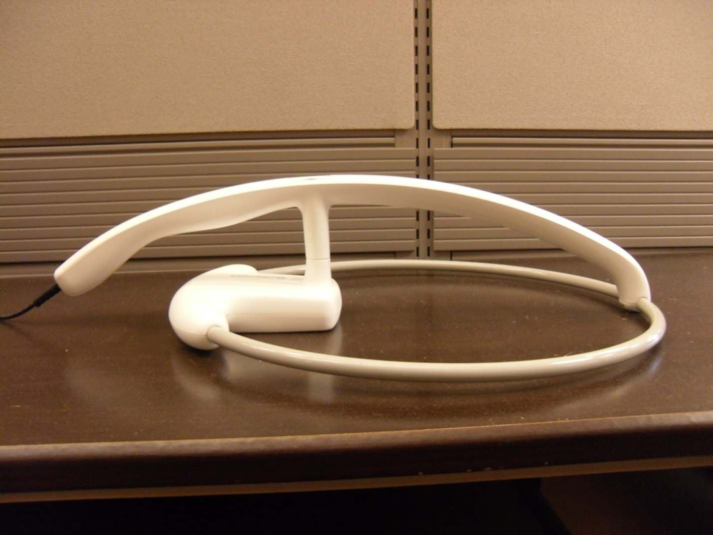
WWQCCMS002Detects & counts surgical items with RFID tags.
ClearCount Medical Solutions Inc.
Click to zoom
Application Details
- Equipment Class
- DXX - Part 15 Low Power Communication Device Transmitter
- Date of Grant
- Jan 27, 2010
- Application Purpose
- Original Equipment
- Date of Application
- Jan 25, 2010
- Equipment Note
- Detects & counts surgical items with RFID tags.
- Frequency Range
- 13.56000000 - 13.56000000
- Country
- United States
Documents & Files
Document Text
Text extracted from the exhibit documents filed with the FCC. Open a document above to read the original.
Users Manual
The SmartWand-DTX System Operating Procedures Manual TM 100936 Rev. A i • • • • • • • • • • • • Preface Indications for Use The ClearCount Medical Solutions SmartWand-DTX ™ System is indicated for use in counting and displaying the number of RFID-tagged surgical sponges, laparatomy sponges, and towels detected by the device and providing a non-invasive means of locating retained RFID-tagged surgical sponges, towels and other tagged items within a surgical site. Wa r n in g s The following list of warnings applies to the SmartWand-DTX System: •Do not use the system in the presence of a flammable anesthetic mixture with air, or with oxygen or nitrous oxide. •For the system to function, use only ClearCount disposables. •Keep the SmartWand-DTX System outside of the sterile field, unless it is properly covered. •The sterility of disposables is guaranteed only for unopened, undamaged packages. Disposables are for single use only; do not re-use or re-sterilize disposables. •Do not cut or tear SmartSponge disposables, as the RFID tags might become separated. •Using the scanning wand without a sterile wand cover could contaminate the sterile field. •Disposables should not be left inside the patient's body for more than 24 hours. •Do not subject patients to an MRI with SmartSponge disposables still inside their body. •Tags may become damaged by surgical lasers. Do not apply a surgical laser directly to a tag. The loss of tag function may result. •Due to possible interference, the system should be separated by at least 1 meter from an active Electrosurgical Unit (ESU). The system should be checked for normal operation to ensure there is no interference present. •No part of the ClearCount SmartWand-DTX System is user serviceable. The system contains no user replaceable fuses. All Service is to be performed by trained personnel. ii • • • • • • Conventions Used Warning! A warning is a statement that identifies conditions or actions that could result in personal injury or loss of life. Caution! A caution is a statement that identifies conditions or actions that could result in damage to the system. Notes A note is an advisory comment or recommendation regarding practices or procedures. Table of Contents • • • • • • Preface ...............................................................................................................................................i Chapter 1: System Description ......................................................................................................1-1 System Components ...................................................................................................1-2 SmartWand Box ............................................................................................1-2 SmartWand....................................................................................................1-4 SmartSponge Disposables.............................................................................1-5 SmartWand Cover.........................................................................................1-7 SmartTags .....................................................................................................1-8 Chapter 2: Initial Setup and Operation ..........................................................................................2-1 Initial Setup ................................................................................................................2-2 Preparing the SmartWand-DTX System for Use ..........................................2-2 Placing the SmartTag ....................................................................................2-3 System Operation .......................................................................................................2-4 Activating the System ...................................................................................2-4 Using the SmartWand ...................................................................................2-5 Deactivating the System ...............................................................................2-7 Chapter 3: Cleaning and Maintenance...........................................................................................3-1 Cleaning Instructions..................................................................................................3-2 Maintenance ...............................................................................................................3-3 Chapter 4: Troubleshooting ...........................................................................................................4-1 General Troubleshooting ............................................................................................4-2 System Message .........................................................................................................4-4 System Error...............................................................................................................4-5 Appendix A: Technical Specifications .........................................................................................A-6 SmartWand-DTX System Dimensions .....................................................................A-6 Power Requirements .................................................................................................A-7 EMC Considerations .................................................................................................A-8 Device Label ...........................................................................................................A-13 1-1 • • • • • • • • • • • • Chapter 1: System Description The SmartWand-DTX ™ System is used in an operating room to detect and identify tagged surgical items for the purpose of preventing a retained foreign body. The system employs radio-frequency identification (RFID) technology to detect ClearCount SmartSponge ® surgical sponges and towels. The system combines detection with the benefit of identif…
Text truncated - open the document above for the full version.
Cover Letter(s)
Non ‐ Conformities FCC ID: WWQCCMS002 (CKC CS Ref # E10 ‐ 000007 ‐ FCC ‐ 01) The items listed below represent requests for information following review of this application for certification under United States (FCC) regulations. Further question may arise pending review of responses to these items. OK ID # Non ‐ Conformity or Comment Submitted Response Respondent / Date of Response √ C 1 Please submit external photos of all sides of the EUT. OK ‐ CKendall 1/25/09 Additional photos uploaded 01/25/2010. K. Whipkey, 1/22/2010. √ C 2 Please provide the RFID Tag return frequency (ies). OK ‐ CKendall 1/25/09 J. Gibala of Clearcount has responded that the tag reflects the 13.56Mhz that is generated by the reader, which is 13.56Mhz but the Tag does not generate the 13.56Mhz. K. Whipkey, 1/22/2010. √ TL 3 Please explain how you satisfied 15.225(e) requirements. OK ‐ CKendall 1/25/09 Please note the reference to the OEM module, FCC ID PJMLRM2000, for compliance to 15.225e on page 3, section 1.5. A copy of that test report has been uploaded 01/25/2010 for your convenience. K. Whipkey, 1/22/2010. √ TL 4 Where is the conducted emission data when the transmitter is on and also in the receive mode? OK ‐ CKendall 1/26/09 F2 report now has the conducted emissions in it. K. Whipkey, 1/26/2010. √ TL 5 Where in this test report is the data when the AC input was varied between 85 ‐ 115% of nominal AC power and where is the data for the variance in temperature from ‐ 20 degrees C to +50 degrees C? Ref: 15.225(e) OK ‐ CKendall 1/25/09 Per J. Gibala of Clearcount, see response to Item 3 above. K. Whipkey, 1/22/2010. √ C 6 Where is the transmitter schematic? There needs to be a schematic that shows the oscillator, antenna and grounding system. The block diagram shows the following clocks: 8, 13.56, 29.4, and 30 MHz yet the schematics do not display the clocks at all. Per J. Gibala of Clearcount: The transmitter schematic is a proprietary Feig electronics document. The transmitter used is FCCID PJRLRM2000. The schematics should be available to K. Whipkey, 1/22/2010. the FCC under that ID. A schematic for OEM MCU module that the client purchases has been uploaded as of 01/25/2010. √ TL 7 Page 19 of the test report F2LQ3776 ‐ 02E displays a Band Edge Plot for 13.56 MHz. This is clearly a peak measurement display. Where is the average reading taking from this peak reading since it appears that the peak is over the limit of the in ‐ band frequency mask? This needs to be blown up to adequately display the emissions versa the limits. There are some close by 15.205 restricted bands adjacent to the fundamental frequency. Nowhere in the report is there a table showing the operating frequency, the individual factors that were taken into consideration in arriving at the corrected readings for both the average and peak readings. The only information depicted is the peak plot shown. A measurement must be made of the fundamental frequency and clearly shown in the test report at the required test distance. Please provide more information regarding this and explain how you applied the correction factors to the measurement you took. OK ‐ CKendall 1/26/09 New report from F2 uploaded K. Whipkey, 1/26/2010 √ C 8 Please submit another request for confidentiality with Jeff Wolfgong signature on it OK ‐ CKendall 1/25/09 A revised letter has been uploaded 01/25/2010. K. Whipkey, 1/22/2010 √ C 9 Please provide internal photos (both sides) of all PCBs that make up the EUT. OK ‐ CKendall 1/25/09 Additional photos have been uploaded 01/25/2010. K. Whipkey, 1/22/2010 √ C/TL 10 Please provide an MPE calculation that shows that you comply with 2.1091(c). 15.225 is exempt from RF exposure testing – 2.1091 and 2.1093 do not apply. No MPE calculations are needed if the field strength measurements meet the 15.225 requirements. I lost the fight over this one (NC #10) so delete this one. Randal Clark 1/21/10 Chuck Kendall 1/21/10 X CKC CS notes: temperature testing provided in a separate test report.
External Photos
Client: Clearcount Medical Solutions F-Squared Laboratories Model: A03 Order No.: F2LQ3776-C1 Smart Wand DTX Front Smart Wand DTX Rear Client: Clearcount Medical Solutions F-Squared Laboratories Model: A03 Order No.: F2LQ3776-C1 Smart Wand DTX Right Smart Wand DTX Left Client: Clearcount Medical Solutions F-Squared Laboratories Model: A03 Order No.: F2LQ3776-C1 Wand Assembly Front Wand Assembly Side Client: Clearcount Medical Solutions F-Squared Laboratories Model: A03 Order No.: F2LQ3776-C1 Wand Assembly LED Panel
ID Label/Location Info
4X R.13 NOTES: MATERIAL: .007" PROTEK POLYESTER, UL / CSA RECOGNIZED 1. REAR ADHESIVE: 3M 9472 HIGH STRENG TH 5 MIL, UL / CSA RECOGNIZED 2. COLORS FOR THE LABEL ARE AS FOLLOWS: 3. Green: Clear Window, DO NOT PRINT (RELIEVE ADHESIVE FROM WINDOW AREA) Magenta: Cut outline, DO NOT PRINT Dark Gray: PMS 10u, light textureWhite: COLOR MATCH WHITE TO SAMPLE PROVID ED BY CLEARCOUNT MEDICAL SOLUTIONS. (CYCOLOY C2950, COLOR WH7154) Blue: PMS 299u, light texture FILE FORMATS ARE AS FOLLOWS: 4. 100614.ai (MASTER), NATI VE ILLISTRATOR FORMAT ECN 1102 SF BY PROJECTION ASME Y14.5M - 1994 REV 04 THIRD ANGLE DESCRIPTION OF CHANGE DWN BY APP DATE 03 DS ECN 1064 9-17-09 JRZJRZ APP 12-2-09 04 INTERPRET GEOMETRIC TOLERANCING PER: LABEL; MODEL-SERIAL NUMBER 100614 SHEET 1 OF 1 SCALE REV DWG. NO. A SIZE .005 CLEARCOUNT MEDICAL SOLUTIONS. OR AS A WHOLE WITHOUT THE WRITTEN PROPRIETARY AND CONFIDENTIAL DRAWING IS THE SOLE PROPERTY OFCLEARCOUNT MEDICAL SOLUTIONS THE INFORMATION CONTAINED IN THISIS PROHIBITED. 5 4 3 2 1 D C B A TITLE: 1:1 MATERIAL: FINISH: CLEARCOUNT MEDICAL SOLUTIONS APP DATE: PERMISSION OF ANY REPRODUCTION IN PART UNITS FOR ALL DIMENSIONS UNLESS OTHERWISE NOTED: InchesFRACTIONAL ANGULAR: MACH 1 BEND 1 TWO PLACE DECIMAL .010 THREE PLACE DECIMAL DO NOT SCALE DRAWING BACKGROUND: WHITE (WH7154) 3.41 2.51
ID Label/Location Info
06 ASME Y14.5M - 1994 THIRD ANGLE PROJECTION D C B AB C D 1 2 3 4 5 6 7 8 8 765 4 3 2 1 E F E F A CHASSIS BOTTOM INTERPRET GEOMETRICTOLERANCING PER: CLEARCOUNT MEDICAL SOLUTIONS 100725 SHEET 1 OF 6 ASSEMBLY; SCALE: 1:4 APP DATE: REV DWG. NO. C SIZE TITLE: FINISH MATERIAL UNITS FOR ALL DIMENSIONS UNLESSOTHERWISW NOTED: INCHESFRACTIONAL: ANGULAR: MACH: 1 BEND 1 TWO PLACE DECIMAL: .010 THREE PLACE DECIMAL: .005 PROPRIETARY AND CONFIDENTIAL THE INFORMATION CONTAINED IN THISDRAWING IS THE SOLE PROPERTY OFCLEARCOUNT MEDICAL SOLUTIONS. ANY REPRODUCTION IN PART OR AS A WHOLEWITHOUT THE WRITTEN PERMISSION OFCLEARCOUNT MEDICAL SOLUTIONS IS PROHIBITED. 4 3 2 1 REVISIONS REV. DESCRIPTION OF CHANGE DWN BY APP BY APPROVED DATE 05 ECN 1074 JRZ DS 10-16-09 06 ECN 1087 JRZ JZ 11-13-09 4X STEP 2 12 INSERT INTO MOUNTING HOLE,THEN PRESS PIN TO SECURE STEP 1 1 STEP 3 LOCATE CABLE MOUNTS APPROXIMATELY AS SHOWN. DIMENSIONS 1. ARE FOR REFERENCE. 1 5 16 " 3 1 4 " BB A A SECTION A-A SCALE 1 : 1 2 1 8 " 20 2 TYPICAL 2 PLCS TORQUE TO 2.5 in-lbs SECTION B-B SCALE 1 : 1 12 13 2" 13 2X THESE SURFACES MUSTBE PARALLEL 28 POSITION LABEL AS SHOWN. CENTER ON POWER ENTRY CUTOUT. REMOVE BACKING AND APPLY FIRMLY. 1 STEP 3A: INSTALL LABEL MODULE CUTOUT POWER ENTRY 1.50 STEP 5 NOTES: INSTALL ITEM 4 (FEIG READER) INTO ITEM 24 1. (ENCLOSURE BASE) AND SECURE WITH ITEMS 15 AND 16. TORQUE AS NOTED. 06 ASME Y14.5M - 1994 THIRD ANGLE PROJECTION D C B AB C D 1 2 3 4 5 6 7 8 8 765 4 3 2 1 E F E F A CHASSIS BOTTOM INTERPRET GEOMETRICTOLERANCING PER: CLEARCOUNT MEDICAL SOLUTIONS 100725 SHEET 2 OF 6 ASSEMBLY; SCALE: 1:4 APP DATE: REV DWG. NO. C SIZE TITLE: FINISH MATERIAL UNITS FOR ALL DIMENSIONS UNLESSOTHERWISW NOTED: INCHESFRACTIONAL: ANGULAR: MACH: 1 BEND 1 TWO PLACE DECIMAL: .010 THREE PLACE DECIMAL: .005 PROPRIETARY AND CONFIDENTIAL THE INFORMATION CONTAINED IN THISDRAWING IS THE SOLE PROPERTY OFCLEARCOUNT MEDICAL SOLUTIONS. ANY REPRODUCTION IN PART OR AS A WHOLEWITHOUT THE WRITTEN PERMISSION OFCLEARCOUNT MEDICAL SOLUTIONS IS PROHIBITED. 4 3 2 1 TORQUE TO 9.6 in-lbs 6X 19 6X 30 3 STEP 4: MCU1 INSTALLATION TORQUE TO 7.0 1.5 in-lbs 9 29 INSTALL ITEM 9, POWER ENTRY MODULE, THRU THE CUTOUT 1. IN THE REAR PANEL AS SHOWN.SECURE WITH (2) TWO #4-40 FLAT HEAD SCREWS (ITEM 18) 2. AS SHOWN.TORQUE TO THE SPECIFICATION NOTED. 3. STEP 7: POWER ENTRY MODULE INSTALLATION 18 4X TORQUE TO 5.2 in-lbs 5 7 1729 STEP 6: POWER SUPPLY INSTALLATION TORQUE TO 19.8 in-lbs TORQUE TO 19.8 in-lbs 3X 24 SLOT FOR CABLE ASSEMBLY (ITEM 8) 29 4 STEP 5: FEIG READER INSTALLATION 15 1629 06 ASME Y14.5M - 1994 THIRD ANGLE PROJECTION D C B AB C D 1 2 3 4 5 6 7 8 8 765 4 3 2 1 E F E F A CHASSIS BOTTOM INTERPRET GEOMETRICTOLERANCING PER: CLEARCOUNT MEDICAL SOLUTIONS 100725 SHEET 3 OF 6 ASSEMBLY; SCALE: 1:4 APP DATE: REV DWG. NO. C SIZE TITLE: FINISH MATERIAL UNITS FOR ALL DIMENSIONS UNLESSOTHERWISW NOTED: INCHESFRACTIONAL: ANGULAR: MACH: 1 BEND 1 TWO PLACE DECIMAL: .010 THREE PLACE DECIMAL: .005 PROPRIETARY AND CONFIDENTIAL THE INFORMATION CONTAINED IN THISDRAWING IS THE SOLE PROPERTY OFCLEARCOUNT MEDICAL SOLUTIONS. ANY REPRODUCTION IN PART OR AS A WHOLEWITHOUT THE WRITTEN PERMISSION OFCLEARCOUNT MEDICAL SOLUTIONS IS PROHIBITED. 4 3 2 1 APPLY PER MANUFACTURERSRECOMMENDATIONS STEP 8: CABLE INSTALLATION 7 8 8 6 9 10 31 APPLY PER MANUFACTURERSRECOMMENDATIONS 31 06 ASME Y14.5M - 1994 THIRD ANGLE PROJECTION D C B AB C D 1 2 3 4 5 6 7 8 8 765 4 3 2 1 E F E F A CHASSIS BOTTOM INTERPRET GEOMETRICTOLERANCING PER: CLEARCOUNT MEDICAL SOLUTIONS 100725 SHEET 4 OF 6 ASSEMBLY; SCALE: 1:4 APP DATE: REV DWG. NO. C SIZE TITLE: FINISH MATERIAL UNITS FOR ALL DIMENSIONS UNLESSOTHERWISW NOTED: INCHESFRACTIONAL: ANGULAR: MACH: 1 BEND 1 TWO PLACE DECIMAL: .010 THREE PLACE DECIMAL: .005 PROPRIETARY AND CONFIDENTIAL THE INFORMATION CONTAINED IN THISDRAWING IS THE SOLE PROPERTY OFCLEARCOUNT MEDICAL SOLUTIONS. ANY REPRODUCTION IN PART OR AS A WHOLEWITHOUT THE WRITTEN PERMISSION OFCLEARCOUNT MEDICAL SOLUTIONS IS PROHIBITED. 4 3 2 1 STEP 8A: CABLE INSTALLATION DETAILS 10 CHASSIS GROUND TO POWERSUPPLY GROUND CABLE ASM 5 9 POWER ENTRY TO POWERSUPPLY CABLE ASM 6 8 21 22 3X 23 TORQUE TO 12 IN-LBS LOCATE APPROX. AS SHOWN 9 POWER ENTRY TO PECABLE ASM 10 06 ASME Y14.5M - 1994 THIRD ANGLE PROJECTION D C B AB C D 1 2 3 4 5 6 7 8 8 765 4 3 2 1 E F E F A CHASSIS BOTTOM INTERPRET GEOMETRICTOLERANCING PER: CLEARCOUNT MEDICAL SOLUTIONS 100725 SHEET 5 OF 6 ASSEMBLY; SCALE: 1:4 APP DATE: REV DWG. NO. C SIZE TITLE: FINISH MATERIAL UNITS FOR ALL DIMENSIONS UNLESSOTHERWISW NOTED: INCHESFRACTIONAL: ANGULAR: MACH: 1 BEND 1 TWO PLACE DECIMAL: .010 THREE PLACE DECIMAL: .005 PROPRIETARY AND CONFIDENTIAL THE INFORMATION CONTAINED IN THISDRAWING IS THE SOLE PROPERTY OFCLEARCOUNT MEDICAL SOLUTIONS. ANY REPRODUCTION IN PART OR AS A WHOLEWITHOUT THE WRITTEN PERMISSION OFCLEARCOUNT MEDICAL SOLUTIONS IS PROHIBITED. 4 3 2 1 CONNECT READER RS232 CABLE END (ITEM 7) THRUSLOT IN COVER (ITEM 25) AND INTO CONNECTOR LOCATED ON FEIG READER (ITEM 4) , AS SHOWNAPPLY A SMALL AMOUNT OF ITEM 31 TO MATING CONNECTORS 6X 25 TORQUE TO 5.2 in-lbs 26 29 WHEN ALL CABLES HAVE BEEN ROUTED TO THEIR PROPER CONNECTION 1. POINTS, INSTALL ITEM 25, ENCLOSURE BLANK-TOP FEIG, AS SHOWN. SECURE WITH (6) TWO #4-40 FLAT HEAD SCREWS (ITEM 26) AS SHOWN. 2. TORQUE TO THE SPECIFICATION NOTED. 3. STEP 9: FEIG ENCLOSURE 7 4 25 APPLY PER MANUFACTURERSRECOMMENDATIONS 31 STEP 10: FEIG READER CABLE INSTALL STEP 11: SECURE CABLES WITH TIE WRAPS 14 SECURE ITEMS 6 & 8 CABLES WITHZIP TIE AT THIS LOCATION 14 SECURE ITEM 8 CABLE WITH ZIP TIEAT THIS LOCATION ITEM NO. QTY CLEARCOUNT PART NUMBER DESCRIPTION DISTRIBUTOR DISTRIBUTOR PART NUMBER MANUFACTURER MANUFACTURER PART NUMBER 31 AR 100909 ADHESIVE-SILICONE; GE RTV 133 NEWARK 00Z1316 GE RTV 133 30 6 100908 Washer No. 4 Screw Size, External-Tooth Lock McMaster Carr 95584A201 29 AR 100154 THREAD LOCK_LOCTITE 242 - - LOCTITE 242 28 1 100811 LABEL; ELECTRICAL SHOCK HAZARD SAFETY LABEL SOLUTIONS 8002K-ISO SAFETY LABEL SOLUTIONS 8002K-ISO 27…
Text truncated - open the document above for the full version.
Internal Photos
Client: Clearcount Medical Solutions F-Squared Laboratories Model: A03 Order No.: F2LQ3776-C1 Console LED PCB Front Console LED PCB Rear Client: Clearcount Medical Solutions F-Squared Laboratories Model: A03 Order No.: F2LQ3776-C1 FEIG DAT Board in Wand Top FEIG DAT Board in Wand Bottom Client: Clearcount Medical Solutions F-Squared Laboratories Model: A03 Order No.: F2LQ3776-C1 FEIG Module Front FEIG Module Rear Client: Clearcount Medical Solutions F-Squared Laboratories Model: A03 Order No.: F2LQ3776-C1 FEIG Module Right FEIG Module Left Client: Clearcount Medical Solutions F-Squared Laboratories Model: A03 Order No.: F2LQ3776-C1 FEIG Module Top FEIG Module Bottom Client: Clearcount Medical Solutions F-Squared Laboratories Model: A03 Order No.: F2LQ3776-C1 LCD PCB Client: Clearcount Medical Solutions F-Squared Laboratories Model: A03 Order No.: F2LQ3776-C1 Power Supply Top Power Supply Bottom Client: Clearcount Medical Solutions F-Squared Laboratories Model: A03 Order No.: F2LQ3776-C1 Wand LED PCB Front Wand LED PCB Rear
Test Report
This report shall not be duplicated except in full without the written approval of F-Squared Laboratories. Form EMC009-102209 Report Number: F2LQ3776-02E Rev. 1 Page 1 of 30 Issue Date: Jan. 25, 2010 F-Squared Laboratories 16740 Peters Road Middlefield, Ohio 44062 (440) 632-5541 Fax: (440) 632-5542 For an RFID Device Manufacturer: Testing Laboratory: Clearcount Medical Solutions, Inc. F-Squared Laboratories 101 Bellevue Road 16740 Peters Road Pittsburgh, Pennsylvania 15229 Middlefield, Ohio 44062 United States of America United States of America The RFID Device, model DTX, was tested and was found to comply with the requirements of the Federal Communications Commission outlined in the Federal Register CFR 47, Part 15.225. The product was received on Dec. 11, 2009 and the testing was completed on Dec. 11, 2009. Evaluation Conducted By: Report Reviewed By: Russell Beattie Wendy Fuster EMC Technical Manager President Certification Test Report Client: Clearcount Medical Solutions, Inc. Order Number: F2LQ3776-C2 Model: DTX Form EMC009-102209 Report Number: F2LQ3776-02E Rev. 1 Page 2 of 30 Issue Date: Jan. 25, 2010 Table of Contents Section Title Page Cover Page 1 Table of Contents 2 1 Engineering Statement 3 2 List of Measurement Instrumentation 5 3 EUT Information and Data 6 4 EUT Configuration and Cables 7 5 Product Description 8 6 FCC Part 15.225(a)-(d) – Radiated Emissions 9 7 Figures – Spectral Data Plots 12 8 Pictorials – Test Setup 24 9 Pictorials – EUT 29 Client: Clearcount Medical Solutions, Inc. Order Number: F2LQ3776-C2 Model: DTX Form EMC009-102209 Report Number: F2LQ3776-02E Rev. 1 Page 3 of 30 Issue Date: Jan. 25, 2010 1. ENGINEERING STATEMENT This report has been prepared on behalf of Clearcount Medical Solutions, Inc. to provide documentation for the testing described herein. This equipment has been tested and found to comply with Part 15.225 of the FCC Rules using ANSI C63.4 2003 standards. The test results found in this test report relate only to the items tested. 1.1. Equipment Under Test: RFID Device FCC ID: WWQCCMS002 1.2. Trade Name: Clearcount Medical Solutions, Inc. 1.3. Model: DTX 1.4. Power Supply: Input: 100-240V~, 50-60 Hz, 1.3A. Output: SL Power Electronics Corp. MINT 1065A2475C01 1.5. Applicable Rules: CFR 47, Part 15.225, (a)-(e) Reference FCC ID PJMLRM2000. Test results for Part 15.225(e) may be found on page 33 of 58 of CETECOM ICT Services GmbH Test Report 2-4112-01-02/05, under separate cover. 1.6. Equipment Category: Low Power Communication Device Transmitter Frequency: 13.56 MHz 1.7. Antenna: Handheld Wand 1.8. Measurement Location: F-Squared Laboratories in Middlefield, Ohio. Site description and attenuation data are on file with the FCC's Sampling and Measurement Branch at the FCC Laboratory in Columbia, MD. Client: Clearcount Medical Solutions, Inc. Order Number: F2LQ3776-C2 Model: DTX Form EMC009-102209 Report Number: F2LQ3776-02E Rev. 1 Page 4 of 30 Issue Date: Jan. 25, 2010 1.9. Measurement Procedure: All measurements were performed according to the 2003 version of ANSI C63.4 and recommended FCC parts 15.31, 15.33 and 15.35. A list of the measurement equipment can be found in Section 2. 1.10. Uncertainty Budget: Conducted Emissions – Combined uncertainly + 1.13 dB, expanded +2.26 dB Radiated Emissions – Combined Uncertainty + 2.24 dB; Expanded Uncertainty +4.48 dB Client: Clearcount Medical Solutions, Inc. Order Number: F2LQ3776-C2 Model: DTX Form EMC009-102209 Report Number: F2LQ3776-02E Rev. 1 Page 5 of 30 Issue Date: Jan. 25, 2010 2. LIST OF MEASUREMENT INFORMATION Equipment Type Asset Number Manufacturer Model Serial Number Calibration Due Date Shield Room CL014 Shielding Resources 3 Meter 001 Aug. 14, 2010 Temp/Hum. Recorder CL118 Extech RH520 H005870 Dec. 11, 2010 Spectrum Analyzer CL129 Hewlett Packard 8591E 3246A00780 Oct. 7, 2010 Receiver 0145 Rohde & Schwarz Display, EASI-0- 804-8932-52; RF Unit, ESMI-RF 1032-5640-53 84982/015; 849152/005 Apr. 23, 2010 Antenna 1-Chamber 0142 ETS/EMCO 3142B 9811-1330 Aug. 31, 2010 Antenna 2-OATS 0105 Sunol Sciences JB1 A101101 July 22, 2011 Pre-Amplifier CL045 Hewlett-Packard 8447D 2944A08445 Oct. 20, 2010 OATS CL017 Compliance Labs N/A 001 Jan. 13, 2010 Transient Limiter CL102 Hewlett Packard 11947A 3107A03325 Dec. 31, 2009 LISN 1 0149 Solar 8028-50-TS-24- BNC 1130 Oct. 20, 2010 LISN 3 0148 Solar 8028-50-TS-24- BNC 1129 Oct. 20, 2010 Client: Clearcount Medical Solutions, Inc. Order Number: F2LQ3776-C2 Model: DTX Form EMC009-102209 Report Number: F2LQ3776-02E Rev. 1 Page 6 of 30 Issue Date: Jan. 25, 2010 3. EQUIPMENT UNDER TEST (EUT) INFORMATION AND DATA 3.1 Test Item Condition: The equipment to be tested was received in good condition. 3.2 Testing Algorithm: The EUT was configured into the wand sweep mode which continuously operated the Tx/Rx. 3.3 Radiated Emission Testing on Open Area Test Site (OATS): The DTX was initially characterized in a semi-anechoic chamber over a frequency range of 0.009 to 1000 MHz. Magnetic field emissions were measured below 30 MHz and electric field emissions were examined above 30 MHz. The final radiated emissions measurements were performed on an Open Air Test Site (OATS). The DTX was tested at a tested at a distance of 3.0 meters at frequencies below 30 MHz and 3.0 meters above 30 MHz. At frequencies below 30 MHz, the emissions were maximized by rotating the Transmitter and the loop antenna on their axes. Additionally, the Transmitter was examined in three orthogonal positions to ensure maximization of emissions. At frequencies above 30 MHz, the emissions were maximized by rotating the Transmitter while raising/lowering the bilog antenna mounted on a 4.0 meter mast. Again, three orthogonal Transmitter positions were examined to ensure maximization of the emissions. Both horizontal and vertical field components were measured above 30 MHz. A resolution bandwidth of 200 Hz was used between 0.009 to 0.15 MHz, 9 kHz was used between 0.15 to 30 MHz, and 120 kHz was used between 30…
Text truncated - open the document above for the full version.
Test Report
CETECOM ICT Services GmbH Untertürkheimer Str. 6-10, 66117 Saarbruecken Phone: +49 (0) 681 598-0 Fax: -9075 RSC-Laboratory Phone: +49 (0) 681 598-0 Fax: -9075 Test report no.: 2-4112-01-02/05 Date: 2005-11-29 Page 1 of 58 Recognized by the Federal Communications Commission Anechoic chamber registration no.: 90462 (FCC) Anechoic chamber registration no.: 3463 (IC) TCB ID: DE 0001 Accredited by the German Accreditation Council DAR–Registration Number DAT-P-176/94-D1 Independent ETSI compliance test house ETSI Accredited Bluetooth ® Test Facility (BQTF) Test report no. : 2-4112-01-02/05 Applicant : Feig Electronics GmbH Type : ID ISC.LRM2000 Transponder reader Test Standard : FCC Part 15 / RSS210 FCC ID : PJMLRM2000 Certification No. IC : CETECOM ICT Services GmbH Untertürkheimer Str. 6-10, 66117 Saarbruecken Phone: +49 (0) 681 598-0 Fax: -9075 RSC-Laboratory Phone: +49 (0) 681 598-0 Fax: -9075 Test report no.: 2-4112-01-02/05 Date:2005-11-29 Page 2 of 58 Table of contents 1 GENERAL INFORMATION ................................................................................................................................... 3 1.1. ADMINISTRATIVE DATA OF THE TEST FACILITY..................................................................................................... 3 1.1.1 Identification of the testing laboratory ......................................................................................................... 3 1.2. NOTES................................................................................................................................................................... 3 1.3 DETAILS OF APPLICANT......................................................................................................................................... 4 1.4 APPLICATION DETAILS.......................................................................................................................................... 4 1.5 TEST ITEM............................................................................................................................................................. 5 1.6 TEST SETUP........................................................................................................................................................... 6 1.7 TEST SPECIFICATIONS............................................................................................................................................ 6 2 STATEMENT OF COMPLIANCE .......................................................................................................................... 7 2.1 SUMMARY OF MEASUREMENT RESULTS................................................................................................................ 7 2.1.1 CFR 47 Part 15 Radio frequency devices ..................................................................................................... 7 3 MEASUREMENTS AND RESULTS ....................................................................................................................... 8 4 FCC PART 15 SUBPART B ...................................................................................................................................... 9 4.1 Timing of the transmitter .................................................................................................................................. 9 4.2 Field strength of the fundamental ................................................................................................................... 10 4.3 Field strength of harmonics and spurious ..................................................................................................... 13 4.4 Frequency tolerance ....................................................................................................................................... 33 4.5 Conducted Limits ............................................................................................................................................ 34 5 ANNEX B: PHOTOGRAPHS OF TEST SITE ..................................................................................................... 39 6 ANNEX C: PHOTOGRAPHS OF THE EQUIPMENT...................................................................................... 44 CETECOM ICT Services GmbH Untertürkheimer Str. 6-10, 66117 Saarbruecken Phone: +49 (0) 681 598-0 Fax: -9075 RSC-Laboratory Phone: +49 (0) 681 598-0 Fax: -9075 Test report no.: 2-4112-01-02/05 Date:2005-11-29 Page 3 of 58 1 General information 1.1. Administrative data of the test facility 1.1.1 Identification of the testing laboratory Company name: Cetecom ICT Services GmbH Address: Untertürkheimerstr. 6-10 D-66117 Saarbruecken Germany Laboratory accreditation: DAR-Registration No. DAT-P-176/94-D1 Bluetooth Qualification Test Facility (BQTF) Federal Communications Commission (FCC) Identification/Registration No : 90462 Responsible for testing laboratory: Harro Ames Phone: +49 681 598 0 Fax: +49 681 598 9075 email: [email protected] 1.2. Notes The test results of this test report relate exclusively to the test item spec…
Text truncated - open the document above for the full version.
Contact Information
Applicant
Jeff Wolfgong(Director, Quality Assurance and Regulatory Affairs)
Technical Contact
ClearCount Medical Solutions, Inc.Jeff Gibala
[email protected]412-931-7233
101 Bellevue Road · Pittsburgh · United States
Non-Technical Contact
F-Squared LaboratoriesKaren Whipkey
[email protected]440-632-5541
Test Firm
F2 LabsWendy Fuster
Technical Specifications
| # | Rule Parts | Frequency Range | Power Output |
|---|---|---|---|
| 1 | 15C | 13.56 MHz - 13.56 MHz | - |
Other Applications from ClearCount Medical Solutions Inc.
WWQCCMS004
Feb 16, 2012SmartSponge Flex Model A04
Equipment Class
DXX - Part 15 Low Power Communication Device Transmitter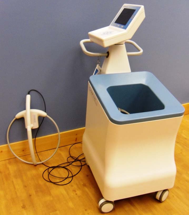
WWQCCMS003
Feb 09, 2010Detects and counts surgical items with RFID tags.
Equipment Class
DXX - Part 15 Low Power Communication Device Transmitter