WWQCCMS004SmartSponge Flex Model A04
ClearCount Medical Solutions Inc.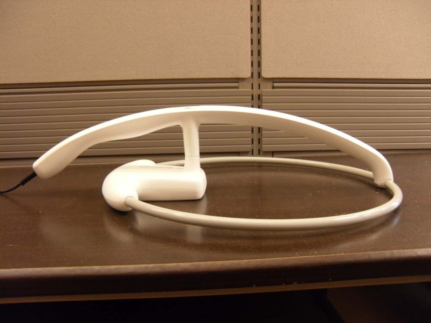
Click to zoom
Application Details
- Equipment Class
- DXX - Part 15 Low Power Communication Device Transmitter
- Date of Grant
- Feb 16, 2012
- Application Purpose
- Original Equipment
- Date of Application
- Feb 16, 2012
- Equipment Note
- SmartSponge Flex Model A04
- Frequency Range
- 13.56000000 - 13.56000000
- Country
- United States
Documents & Files
Document Text
Text extracted from the exhibit documents filed with the FCC. Open a document above to read the original.
Users Manual
i • • • • • • • • • • • • Preface Indications for Use The ClearCount Medical Solutions SmartSponge ® Basin is indicated for use in counting and recording the number of RFID-tagged surgical gauze, laparotomy sponges, and towels used during surgical procedures. It also provides a non-invasive means of locating retained radio-frequency identification (RFID)-tagged surgical sponges, towels, and other tagged items within a surgical site. Wa r n in g s The following list of warnings applies to the SmartSponge Flex: •Use only one SmartSponge Flex during a surgical procedure. •Do not dispose of sponges from a previous surgical case into the Count Out Basin. Sponge counts may not reconcile properly. Use only sponges from the current surgery. •Do not use the system in the presence of a flammable anesthetic mixture with air, or with oxygen or nitrous oxide. •For the system to function, use only ClearCount disposables. •Keep the SmartSponge Flex outside of the sterile field, unless it is properly covered. •Place only ClearCount disposables in the Count Out Basin. •The sterility of disposables is guaranteed only for unopened, undamaged packs. Disposables are for single use only; do not re-use or re-sterilize disposables. •Do not cut or tear ClearCount disposables, as the RFID tags might become separated. •When scanning items contained in a sterile surgical kit (bundles of items not in their own sterile packs) into the SmartSponge Flex, cover the system with the sterilized liner from the surgical kit. This prevents contamination of the items being scanned. •Using the wand without a sterile wand cover could contaminate the sterile field. •Holding items that have been scanned in too close to the Count Out Basin may result in these items being added to the Out column of the inventory (detected) prior to use and disposal. Dispose of any items into the Count Out Basin without using them if they have been counted out prior to use. •Disposables should not be left inside the patient's body for more than 24 hours. ii • • • • • • •When using the wand, the system may experience a slight degradation of read range of RFID tagged items when metal objects are within the scanning field. Small metal objects like implants and pacemakers will have no impact in most cases. To the extent possible, remove metal from the scanning site or keep the RFID tags at least ½ an inch from direct contact with metal objects. •Individual sponges or packs of sponges may not correctly count when placed directly on metal surfaces including back tables, mayo stands, large reusable capacitively-coupled return electrode pads and metal kick buckets. When using the wand, remove the sponges from those areas, or provide a separation distance between the metal and the RFID tags so that the tags can be read. •When using a SmartTag in conjunction with a large reusable capactively-coupled return electrode pad, it is necessary to place the tag lateral to the pad in order for the wand to detect it. The SmartTag will not be detected if applied directly to the pad because of its metal interior. •While using the wand, interference may appear momentarily on ECG graphs. Users should be aware that this interference is temporary and will discontinue when the wand is moved away from ECG equipment or when wand use is discontinued. •While using the wand interference may appear on Ultrasound images. Place the device in Standby while ultrasound imaging is in progress. The device will not lose count when in Standby. •The wand is a tool to assist in the location of tagged items within the body. Use of the wand, does not guarantee that a tagged item will be detected. Detection depends on proper technique and a variety of environmental conditions. •The orientation of the RFID tags within a body has an effect on the ability to read those tags. For this reason, proper wand technique should be exercised when searching for tagged items. Proper technique requires deliberate and thorough scanning through various orientations. See Chapter 4 of this operators manuals for complete details. •Packs of sponges, either partial or complete, may not count when discarded into the Count Out Basin. If a pack is discarded and fails to read, separate the sponges from each other to ensure a correct count. •Tags may become damaged by surgical lasers. Do not apply a surgical laser directly to a tag. The loss of tag function may result. •Due to possible interference, the system should be separated by at least 1 meter from an active Electrosurgical Unit (ESU). The system should be checked for normal operation to ensure there is no interference present. •No part of the ClearCount SmartSponge Flex is user serviceable. The system contains no user replaceable fuses. All Service is to be performed by trained personnel. •Cardiac pacers should be set to asynchronous pacing (VOO/DOO) mode prior to patient scanning with the wand to avoid potential short-term interference. iii • • • • • • Conventions Used Warning! A warning is a statement that identifies conditions or actions that could result in personal injury or loss of life. Caution! A caution is a statement that identifies conditions or actions that could result in damage to the system. Notes A note is an advisory comment or recommendation regarding practices or procedures. iv • • • • • • Table of Contents • • • • • • Preface .............................................................................................................................................................i Chapter 1: System Description .................................................................................................................. 1-1 Counting System ...................................................................................................................... 1-3 SmartWand .............................................................................................................................. 1-5 Mobile Cart ................................…
Text truncated - open the document above for the full version.
Cover Letter(s)
,:: .r;r clearcount L*iiit IrF3 \, f r. \- r ir:ii hlEDtcAL saLL)rraNs February 6,2012 To Whom It May Concern: I hereby authorize Franck D'Annunzio of TAGSYS RFID to act on our behalf only for signing the Request for Confidentiality letter for this filing FCC ID:WWQCCMS004. r[e exhiUits being held confidential are the intellectual property of TAGSYS RFID. This authorization is limited to only the signing of the Request for Confrdentiality letter. This authorizationshall expire l2 months from original date. Sincerely, ftrl a"tr% Jeff Wolfgong VP of QA/RA and Service 101 Bette"ue Rd. Suite 203, Pittsburgh, PA 15229 Phone: 412.931.7233 Fax:4'12.291.1091
Cover Letter(s)
Northwest EMC TCB Compliance Opinion Rev. 7/1/10 KEYS0009 Information about the Applicant Grantee (Company Name) ClearCount Medical Solutions, Inc. FCC Contact Person Jeff Wolfgong Address 101 Bellevue Road, Suite 300 City, State, Zip Pittsburg, PA 15229 Job Number KEYS0009 Model SmartSponge Flex A04 FCC ID WWQCCMS004 Agent Franck D'Annunzio Approval Type Original Equipment Class DXX Part 15, Low Power Communication Device Transmitter Rule Part 15C Overview The SmartSponge Flex Model A04 is a component of the ClearCount's SmartSponge system, which includes surgical sponges, laparatomy pads and surgical towels. Each of these components contains unique RFID tags. The Model A04 employs a radio, operating at 13.56 MHz to manage the various components of the system in the surgical suite. Confidentiality requested for allowed files. Request is properly addressed and referenced. Short term confidentiality requested. Recommendation All items have been resolved and completed to my satisfaction; therefore I recommend this application for approval. Signature Dave Tolman, TCB Committee 2/16/2012
Cover Letter(s)
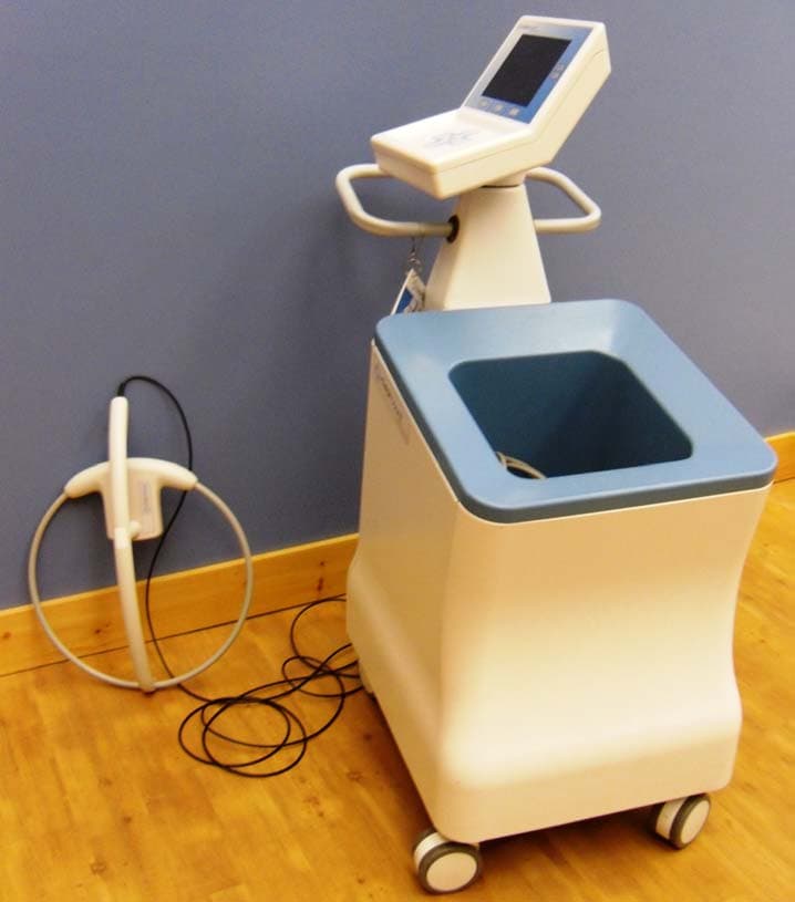
101 Bellevue Rd. Suite 203, Pittsburgh, PA 15229 Phone: 412.931.7233 Fax: 412.291.1091 February 17, 2012 To Whom It May Concern: The following application is for the ClearCount Medical Solutions, Inc. SmartSponge Flex Model A04 system. This application is for original certification of FCC ID: WWQCCMS004 to FCC rule part 15.225. The SmartSponge Flex Model A04 incorporates a high frequency radio frequency identification (RFID) radio, model Medio L40. The radio transmit frequency is 13.56 MHz and it operates to the ISO15693 standard. The frequency stability information required by FCC rule part 15.225(e) is incorporated by reference to the report for Medio L40 radio, FCC ID: QHKMEDIOL40. A copy of this report is submitted with this application. The SmartSponge Flex Model A04 is a specially designed cart mounted device containing a microcontroller unit with specialized software designed for data collection. Integrated RFID technology allows capture of the information coded on the unique RFID tag on the sponges, pads and towels. The microcontroller unit counts the initial number of sponges introduced into a surgical case, and using the custom software program, reports the total sponges discarded at the end of the procedure, and compares that number to the original. By providing a count of the items entered into surgery, and a count of those discarded and removed permanently from the surgical field, personnel can be alerted to sponges that may still remain in the surgical field prior to closing the patient. A Detection Wand is an additional antenna that is tethered by a cable to the SmartSponge Flex Model A04. It is powered and controlled by the SmartSponge Flex Model A04. The antenna functions as an additional RFID antenna to the system, functioning in an identical manner to the SmartSponge Flex Model A04 internal antennas. By using a keypad the user may select to activate the Detection Wand antenna. When in Detection Wand mode, the system uses the Wand antenna to recognize RFID-tagged items that may be inside the surgical site. The ClearCount Medical Solutions SmartSponge Flex Model A04® System is indicated for use in counting and recording the number of RFID-tagged surgical sponges, laparatomy sponges and towels used during surgical procedures, as well as for providing a non-invasive means of locating retained RFID-tagged surgical sponges, towels, and other tagged items within a surgical site. Sincerely, Jeff Wolfgong VP of QA/RA and Service
Cover Letter(s)
il::-:ll , ; r clearc0unt i-ill ilEOtCAL SOLUTTONS January 27,2012 Federal Communications Commission 7435 Oakland Mills Road Columbia, MD 21046 Gentlemen: This letter is to comply with Section 0.457(dxii) and section 0.459 pertaining to confidential material ClearCount Medical Solutions, Inc. would like the following documents regarding this submission for FCC ID: WWQCCMSO04 to be kept confidential. We request long term confidentiality for the following items. l. Frequency Block Diagram 2. System Description 3. All schematics The above material contains trade secrets or technical data, which would customarily be guarded from competitors. We do not want these documents to be accessible to the general public. In addition to the items listed above, per Public Notice DA 04-1705, ClearCount Medical Solutions requests holding the following exhibits confidential short term until 05/0Il 2012. 1. Device Internal Photos 2. Users Manual 3. Antenna Details public availability of the above information prior to release of the product would be a competitive disadvantage for ClearCount Medical Solutions. The requested conf:rdentiality period will allow the product to be introduced to the Market prior to release of these documents' Sincerely, ffirfu Jeff Wolfgong VP of QA/RA and Service 101 Beitevue Rd. Suite 203, Pittsburgh, PA 15229 Phone: 412.931.7233 Fax: 412.291.1091
Cover Letter(s)
785 Voie Antiope - Athélia III - 13600 La Ciotat - France Tél : +33 (0)4-4218-8900 - Fax : +33 (0)4-4518-8901 Siret : 437 748 486 TAGSYS RFID LA CIOTAT FRANCE Monday, 06 February 2012 To whom it may concern, I hereby request the exhibits listed below to be held confidential for the filing of the FCC ID: WWQCCMS004. - Schematics – MEDIO L40 (file: SCH13901B1_MedioL40_Reader.pdf) - Block Diagram– MEDIO L40 (file: Medio_L40_Block_Diagram.pdf) The exhibits being held confidential are the intellectual property of TAGSYS RFID. This authorization shall expire 12 months from original date. Yours Sincerely, FRANCK D’ANNUNZIO Product Design Director
External Photos
System (Front View) System (Rear View) System (Side View) System (Side View) System (Top View) Wand (Top View) Wand (Side View) Wand (Rear View) Wand (Side View) Wand (Front View) Wand (Bottom View)
ID Label/Location Info
COMPONENT SPECIFICATION SHEET CCM PART NO. REVISION LABEL, MODEL AND SERIAL NUMBER 101511 01 Page 1 of 1 For use by affiliates of ClearCount Medical Solutions. This document contains proprietary information and may not be reproduced or disclosed without prior written approval. A printed version of this document is considered an uncontrolled copy. The user of this document is responsible for verifying the current revision level. PHYSICAL CHARACTERISTICS / SPECIFICATIONS: MATERIAL: o .007” PROTEK POLYESTER, UL/CSA RECOGNIZED REAR ADHESIVE: o 3M 9472 HIGH STRENGTH 5 MIL, UL/CSA RECOGNIZED o NO ADHESIVE IN CLEAR WINDOW AREA ARTWORK DIMENSIONS: o 2.51” HIGH X 3.41” WIDE COLORS AS PER ADOBE ILUSTRATOR FILE 101511-01.AI o BACKGOUND: WHITE o TEXT: BLACK o CLEARCOUNT LOGO: DARK GRAY, PMS 10U, LIGHT TEXTURE BLUE, PMS 299U, LIGHT TEXTURE SUPPLIER INFORMATION: Possible Manufacturers Manufacturer Part No. Possible Distributors Distributor Part No. Butler Technologies 101511 - - SPECIAL HANDLING: N/A SHELF LIFE: N/A REVISION HISTORY: Revision Effective Date Change Notice # Contributor(s) 01 12/21/2011 ECN 1240 H. Suwalski CLEAR WINDOW 2.51 +/- .01 3.41 +/- .01 4X R.13 1 2 3 4 5 6 7 8 A B C D 1 2 3 4 5 6 7 8 A B C D INTERPRET GEOMETRIC TOLERANCING PER: ASME Y14.5M - 1994 THE INFORMATION CONTAINED IN THISDRAWING IS THE SOLE PROPERTY OFCLEARCOUNT MEDICAL SOLUTIONS. ANYREPRODUCTION IN PART OR AS A WHOLEWITHOUT THE WRITTEN PERMISSION OFCLEARCOUNT MEDICAL SOLUTIONS ISPROHIBITED. PROPRIETARY AND CONFIDENTIAL UNITS FOR ALL DIMENSIONS UNLESSOTHERWISE NOTED: INCHES FRACTIONAL: ANGULAR: MACH: 1 BEND: 1 TWO PLACE DECIMAL: .010 THREE PLACE DECIMAL: .005 MATERIAL: FINISH: THIRD ANGLEPROJECTION SCALE: REV DWG. NO. SIZE TITLE; CLEARCOUNT MEDICAL SOLUTIONS C A PRINTED VERSION OF THIS DOCUMENT IS CONSIDERED AN UNCONTROLLED COPY.THE USER OF THIS DOCUMENT IS RESPONSIBLE FOR VERIFYING THE CURRENT REVISION LEVEL. .75 1.00 SHEET 3 OF 3 0.400 101517 SYSTEM, LCCD -- 03 STEP 3: ATTACH SERIAL LABEL AND BACK COVER 1. CLEAN THE SURFACE AREA ON THE COVER/SCREEN ASSEMBLY (101658) WHERE THE SERIAL NUMBER LABEL (101511) WILL BE APPLIED WITH ISOPROPYL ALCOHOL AND LET DRY. 2. PRINT SERIAL NUMBER PER PROCEDURE CCM-WI-01. POSITION THE PRINTED SERIAL NUMBER SO THAT IT IS CENTERED AND SHOWS THROUGH THE CLEAR WINDOW OF 101511. INSTALL THE SERIAL NUMBER LABEL (101511) TO THE BACK OF THE COVER/SCREEN ASSEMBLY (101658) AS SHOWN. 3. PRESS TO MAKE SURE THAT THE LABEL IS FULLY SEATED. 4. INSTALL THE BACK COVER (101653) TO THE COVER/SCREEN ASSEMBLY (101658) USING 4 SCREWS (101576). TORQUE SCREWS TO 12 +/- 1 IN-LBS. STEP 4: FUNCTIONAL TEST 1. TEST SYSTEM PER TEST PROCEDURE 101560 - FINAL FUNCTIONAL TEST FOR THE LCCD SYSTEM. 2. REMOVE BOTH PIECES OF TEMPORARY TAPE FROM THE OVERLAY INCLUDED WITH TOP COVER ASSEMBLY (101658) AND INSTALL IN THE MATCHING RECESS ON THE TOP COVER ASSEMBLY. 3. PRESS TO MAKE SURE THAT THE LABEL IS FULLY SEATED. 4 3 8 SEE NOTE 2 5 SCALE 0.800 5
Internal Photos
Wand Antenna Board Antenna Antenna Cable Wand Antenna Board Wand Antenna Board (Bottom View) System (Side View Cover Removed) In-Scan Antenna Radio Antenna Cables Out-Scan Antenna System (Front View Cover Removed) In-Scan Antenna Radio Antenna Cables Out-Scan Antenna System (Side View Cover Removed) In-Scan Antenna Radio Antenna Cables Out-Scan Antenna System (Rear View Cover Removed) In-Scan Antenna Antenna Cables System (Top View Cover Removed) In-Scan Antenna Radio Out-Scan Antenna Antenna Cables Out-scan Antenna Board Out-scan Antenna Board (Bottom View) In-scan Antenna Board In-scan Antenna Board (Bottom View) Control Board Control Board (Bottom View) Speaker Assembly and Power Supply Antenna Cables Power Supply Power Supply (Bottom View) Reader (Top View) Reader (Bottom View) Reader (Side View) Reader (Side View) Display Adapter Board Display Adapter Board (Bottom View) Display Display (Bottom View)
Operational Description
Rev. 1 1/24/12 1 ClearCount SmartSponge Flex Antenna Details The SmartSponge Flex system incorporates multiple custom antennas. Which specific antennas are active depend on the device operating mode. The SmartSponge Flex modes of operation are Count In, Count Out and Wand. Count In and Count Out mode are also referred to as Scan In and Scan Out. Each operating mode uses a specific antenna(s). Count In mode utilizes a dedicated rectangular loop antenna that is approximately 5.125” x 9”. In Count Out mode uses an array of 3 square loop antennas, each antenna is driven sequentially with only one antenna driven at a time. Two of the loops measure 12.5” x 12.5” and the third measures 13.75” x 13.75”. In Wand mode a tethered hand held antenna is driven. This antenna is referred to as either the Wand or SmartWand. This antenna is circular loop with an diameter of 16.25”. 15.203 Compliance Compliance with section 15.203 is accomplished with permanently attached antennas and unique identification information integrated into the system antennas. The unique identification information is programmed into each antenna and can be read by the system radio. When a system antenna is active the radio detects and reads the information embedded in the antenna and if the information does not match what is expected the system will go into error mode shutting off the RF. If an antenna that was not provided with the system was connected to the radio the unique identification information would be missing and the system will error and shutdown. Rev. 1 1/24/12 2 Figure 1- Count In /Count Out Antenna Photo Count In Antenna Bottom Count Out Antenna Center Count Out Antenna Top Count Out Antenna Rev. 1 1/24/12 3 Figure 2- Count Out Antenna Top View Wand Antenna The system Wand is a single loop antenna that is tethered to system by RG58 coax. The inside diameter of the loop is 16.25”. Count Out Antenna’s Rev. 1 1/24/12 4 Figure 3- Wand photo 16.25”
Test Report
ClearCount Medical Solutions SmartSponge Flex February 16th, 2012 Report Number: 1106-039E Rev. C Report Prepared By: EMC Test Report www.keystonecompliance.com 724-657-9940 Keystone Compliance, LLC. 2 of 72 Report Number: 1106-039E Rev. C - Purchase Order Number: 11168 Performed By: Keystone Compliance, LLC. 2861 W. State Street New Castle, PA 16101 Keystone Compliance, LLC., does hereby certify that all inspection(s) and test(s) have been performed in accordance with the documents referenced herein with exceptions as noted in this report. The results in this report pertain only to the specified equipment tested. This report shall not be reproduced, except in full, without the written approval of Keystone Compliance, LLC. This report must not be used by the client to claim product certification, approval, or endorsement by NIST, A2LA, or any agency of the Federal Government. Tech. Writer: Date: February 16th, 2012 Coy Price, Technical Writer Reviewed By: Date: February 16th, 2012 Ronald Hague, EMC Engineer Reviewed By: Date: February 16th, 2012 Eva Maxwell, Quality Manager Approved By: Date: February 16th, 2012 Andrew Catterall, EMC Lab Manager Revisions 3 of 72 Report Number: 1106-039E Rev. C - Purchase Order Number: 11168 Revisions Revision: Description: A Revised to incorporate customer comments on initial issue, as follows: Corrected Customer Name Spelling Added Wand Part Number and Serial Number to Peripheral Table for Configuration 1 Changed Conducted Emissions Comments to reflect the correct installation and removal of 50Ω loads Added “Per FCC publication 174176” as Deviation from Test Standard for Conducted Emissions Corrected Operating Mode Information on Test Data Sheets Added notation for peak frequency of 13.56MHz on Conducted Emissions Plots Added Quasi Peak Radiated Emissions plot (page 63) for Wand Mode B Revised to incorporate additional customer comments, as follows: Amended customer name to use complete form Changed configuration table to include Part Number and Serial Number of the EUT Test Data Sheets equipment lists updated. C Revised to incorporate FCC submittal review comments, as follows: Sample calculations and their application to the computed data has been illustrated Antenna factors have been added Field strength of intentional transmitter has been stated on datasheets, where applicable The results of frequency stability measurements required by 15.225(e) 4 of 72 Report Number: 1106-039E Rev. C - Purchase Order Number: 11168 Table of Contents Title Page ............................................................................................................................ 1 Signature Page ..................................................................................................................... 2 Revisions ............................................................................................................................. 3 Table of Contents ................................................................................................................ 4 Product Description ............................................................................................................. 5 Configurations ..................................................................................................................... 6 Executive Summary ............................................................................................................. 7 Acronyms and Abbreviations ............................................................................................... 8 Conducted Emissions .......................................................................................................... 10 Radiated Emissions ............................................................................................................. 50 Frequency Stability ............................................................................................................. 68 Appendix A – EUT & Test Photos ......................................................................................... 69 End of Report ..................................................................................................................... 72 Product Description 5 of 72 Report Number: 1106-039E Rev. C - Purchase Order Number: 11168 Party Requesting the Test Company Name: ClearCount Medical Solutions Address: 101 Bellevue Rd. City, State, Zip: Pittsburgh, PA 15229 Test Requested By: Jeff Gibala Description: SmartSponge Flex Model: SmartSponge Flex First Date of Test: 11/10/2011 Last Date of Test: 11/11/2011 Receipt Date of Samples: 11/10/2011 Equipment Condition: No Damage Information Provided by the Party Requesting the Test Operational Description of the EUT (Equipment Under Test): SmartSponge Flex Testing Objective: To perform testing and evaluation to the customer’s requirements to demonstrate compliance to the current FCC standard CFR 47, Part 15.207, Part 15.209, Part 15.225 EUT Photo(s) Configurations 6 of 72 Report Number: 1106-039E Rev. C - Purchase Order Number: 11168 Configuration 1 EUT Description Manufacturer Part Number Model Number Serial Number SmartSponge Flex ClearCount Medical Solutions 101517 A04 ENG002 Peripherals Description Manufacturer Part Number Model Number Serial Number Wand ClearCount Medical Solutions 101714 N/A CAT002 SMARTSPONGE FLEX Test Configuration Executive Summary 7 of 72 Report Number: 1106-039E Rev. C - Purchase Order Number: 11168 Executive Summary Test Specification(s): FCC Part 15 Item Test Modification(s) Note(s) Disposition of EUT Test Result 1. Conducted Emissions FCC Part 15.207 Tested as delivered to Test Station. No EMI suppression devices were added or modified during this test. Upon completion of testing, the items were returned to the customer for further evaluation Compliant 2. Radiated Emissions FCC Part 15.209 FCC Part 15.225 Tested as delivered to Test Station. No EMI suppression devices were added or modified during t…
Text truncated - open the document above for the full version.
Test Report
Rapport d’essai / Test report N° 96350-A1-R2-E JDE : 105566 DELIVRE A / ISSUED TO : TAGSYS RFID 785 Voie Antiope Athélia III 13600 LA CIOTAT - FRANCE Objet / Subject : Essais de compatibilité électromagnétique conformément aux normes FCC CFR 47 Part 15, Subpart B et C. Electromagnetic compatibility tests according to the standards FCC CFR 47 Part 15, Subpart B and C Matériel testé / Apparatus under test : • Produit / Product : Lecteur RFID / RFID Reader • Marque / Trade mark : TAGSYS RFID • Constructeur / Manufacturer : TAGSYS RFID • Type / Model : MEDIO L40 + ANTENNAS • N° de série / serial number : T1111002A0 • Type d’antenne / Antenna Model AERO LB / AERO LC / MAT / LSA3 / LSA4 • N° de série / serial number See configuration page 5 • FCC ID : QHKMEDIOL40 Date des essais / Test date : Du 21 au 29 Mars 2011 / From March 21st to 29th, 2011 Lieu d’essai / Test location : LCIE SUD-EST ZI Centr’Alp – 170 rue de Chatagnon 38430 MOIRANS - FRANCE Test réalisé par / Test performed by : Anthony MERLIN Ce document comporte /Composition of document : 73 pages. M OIRANS, LE 5 MAI 2011 / MAY 5TH, 2011 Ecrit par / Written by Approuvé par / Approved by, Anthony MERLIN Yannick SAVOIE La reproduction de ce document n'est autorisée que sous sa forme intégrale. Toute reproduction partielle ou toute insertion de résultats dans un texte d'accompagnement en vue de leur diffusion doit recevoir un accord préalable et formel du LCIE. Ce document résulte d’essais effectués sur un spécimen, un échantillon ou une éprouvette. Il ne préjuge pas de la conformité de l’ensemble des produits fabriqués à l’objet essayé. Sauf indication contraire, la décision de conformité prend en compte l’incertitude de mesures. Il ne préjuge en aucun cas d’une décision de certification. This document shall not be reproduced, except in full, without t he written approval of the LCIE. This document contains results related only to the item tested. It does not imply the conformity of the whole production to the item tested .Unless otherwise specified; the decision of conformity takes into account the uncertainty of measures. This document does not anticipate any certification decision. RAPPORT D'ESSAI / TEST REPORT N° 96350-A1-R2-E Page : 2 / 73 SUMMARY 1. TEST PROGRAM ................................................................................................................................... 3 2. SYSTEM TEST CONFIGURATION ........................................................................................................ 4 3. RADIATED EMISSION DATA ................................................................................................................. 6 4. FUNDAMENTAL FREQUENCY TOLERANCE (15.225E) ..................................................................... 15 5. BAND-EDGE COMPLIANCE §15.209................................................................................................. 17 6. CONDUCTED EMISSION DATA .......................................................................................................... 23 7. ANNEX 1 (GRAPHS) ............................................................................................................................ 31 8. TEST EQUIPMENT LIST ...................................................................................................................... 72 9. UNCERTAINTIES CHART .................................................................................................................... 73 RAPPORT D'ESSAI / TEST REPORT N° 96350-A1-R2-E Page : 3 / 73 1. TEST PROGRAM Standard: - FCC Part 15, Subpart B (Digital Devices) - ANSI C63.4 (2009) EMISSION TEST LIMITS RESULTS (Comments) Frequency Quasi-peak value (dBμV) Average value (dBμV) 150-500kHz 66 to 56 56 to 46 0.5-5MHz 56 46 Limits for conducted disturbance at mains ports 150kHz-30MHz 5-30MHz 60 50 PASS Radiated emissions 30MHz-2GHz* Measure at 3m 30MHz-88MHz : 40 dBμV/m 88MHz-216MHz : 43.5 dBμV/m 216MHz-960MHz : 46.0 dBμV/m Above 960MHz : 54.0 dBμV/m PASS Standard: - FCC Part 15, Subpart C - ANSI C63.4 (2009) EMISSION TEST LIMITS RESULTS (Comments) Frequency Quasi-peak value (dBμV) Average value (dBμV) 150-500kHz 66 to 56 56 to 46 0.5-5MHz 56 46 Limits for conducted disturbance at mains ports 150kHz-30MHz 5-30MHz 60 50 PASS Radiated emissions 9kHz-30MHz Measure at 300m 9kHz-490kHz : 67.6dBμV/m /F(kHz) Measure at 30m 490kHz-1.705MHz : 87.6dBμV/m /F(kHz) 1.705MHz-30MHz : 29.5 dBμV/m PASS Radiated emissions 30MHz-2GHz* Measure at 3m 30MHz-88MHz : 40 dBμV/m 88MHz-216MHz : 43.5 dBμV/m 216MHz-960MHz : 46.0 dBμV/m Above 960MHz : 54.0 dBμV/m PASS Fundamental frequency tolerance Operation within the band 13.110-14.010 MHz §15.225 PASS Bandedge compliance Operation within the band 13.110-14.010 MHz §15.225 PASS *§15.33: The highest internal source of a testing device is defined like more the highest frequency generated or used in the testing device or on which the testing device works or agrees. - If the highest frequency of the internal sources of the testing device is lower than 108 MHz, measurement must be only performed until 1GHz. - If the highest frequency of the internal sources of the testing device ranges between 108 MHz and 500 MHz, measurement must be only performed until 2GHz. - If the highest frequency of the internal sources of the testing device ranges between 500 MHz and 1 GHz, measurement must be only performed until 5GHz. If the highest frequency of the internal sources of the testing device is above 1 GHz, measurement must be only performed until 5 times the highest frequency or 40 GHz, while taking smallest of both. RAPPORT D'ESSAI / TEST REPORT N° 96350-A1-R2-E Page : 4 / 73 2. SYSTEM TEST CON…
Text truncated - open the document above for the full version.
Contact Information
Applicant
Jeff Wolfgong(Director, Quality Assurance and Regulatory Affairs)
Test Firm
Keystone Compliance, LLC.Anthony Masone
Technical Specifications
| # | Rule Parts | Frequency Range | Power Output |
|---|---|---|---|
| 1 | 15C | 13.56 MHz - 13.56 MHz | - |
Other Applications from ClearCount Medical Solutions Inc.
WWQCCMS003
Feb 09, 2010Detects and counts surgical items with RFID tags.
Equipment Class
DXX - Part 15 Low Power Communication Device Transmitter
WWQCCMS002
Jan 27, 2010Detects & counts surgical items with RFID tags.
Equipment Class
DXX - Part 15 Low Power Communication Device Transmitter