WYHFW3817-40ECOSTONE
NEO-TELECOM CORPORATION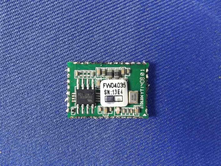
Click to zoom
Application Details
- Equipment Class
- DSS - Part 15 Spread Spectrum Transmitter
- Date of Grant
- Jul 31, 2014
- Application Purpose
- Original Equipment
- Date of Application
- Jul 30, 2014
- Equipment Note
- ECOSTONE
- Frequency Range
- 2402.00000000 - 2480.00000000
- Company
- NEO-TELECOM CORPORATION
- Country
- South Korea
Documents & Files
Document Text
Text extracted from the exhibit documents filed with the FCC. Open a document above to read the original.
Users Manual
1 / 4 Bluetooth Module Datasheet Model: FW3817-40 Version:V1.4 2014-2-9 2 / 4 1 Introduction Introduces the pioneer of the Bluetooth 3.0modules FW3817-40 which is a high performance, cost effective, low power and compact solution. The Bluetooth module provides a complete 2.4GHz Bluetooth system based on the Blue Core CSR8640 chipset which is a single chip radio and base band IC for Bluetooth 2.4GHz systems. This module is fully compliant to Bluetooth v3.0 for audiocommunications. 2 Key Features Bluetooth Profiles Bluetooth v3.0 specification support HFPv1.6 wide band speech (HDvoiceready) HSPv1.2 A2DPv1.2 AVRCPv1.4 Support for smartphone applications(apps) Improved Audio Quality mSBC codec support for wideband speech 2-mic far-end audio enhancements Near-end audio enhancements(noise suppression and AEQ) Wind noise reduction Packet loss concealment Bit error concealment Automatic gain control and automatic volume control Frequency expansion for improved speech intelligibility Music Enhancements Configurable 5-band EQ for music playback (rock, pop, classical, jazz, dance etc) SBC, MP3, AAC and faststream decoder Stereo widening (S3D) Volume Boost Wired Audio Mode supported USB Audio Mode supported 3 / 4 Additional Functionality Support for Voice recognition for answering a call, enables true hands-free use Support for multi-language programmable audio prompts CSR’s proximity pairing and CSR’s proximity connection Multipoint support HFP connection to 2 handsets for voice Multipoint support A2DP connection 2 A2DP source devices for music playback Talk-time extension Slim module with 21mm*14.7mm*2.0mm 3 Applications Stereo Headsets Wired Stereo headsets and headphones Portable Bluetooth Stereo speakers 4 General Specifications Mode Name FW3817-40 Product Description Bluetooth 3.0 class 2 module Bluetooth Standard Bluetooth 3.0 Chipset CSR8640 Dimension 21mm*14.7mm*2.0mm Operating Conditions Voltage 2.8~ 4.2V Temperature -10~ +70°C Storage Temperature -40~ +85°C Electrical Specifications Frequency Range 2402-2480MHz Maximum RF Transmit Power 4dBm Receive Sensitivity -82dBm 4 / 4 FCC STATEMENT 1. This device complies with Part 15 of the FCC Rules. Operation is subject to the following two conditions: (1) This device may not cause harmful interference. (2) This device must accept any interference received, including interference that may cause undesired operation. 2. Changes or modifications not expressly approved by the party responsible for compliance could void the user's authority to operate the equipment. NOTE: This equipment has been tested and found to comply with the limits for a Class B digital device, pursuant to Part 15 of the FCC Rules. These limits are designed to provide reasonable protection against harmful interference in a residential installation. This equipment generates uses and can radiate radio frequency energy and, if not installed and used in accordance with the instructions, may cause harmful interference to radio communications. However, there is no guarantee that interference will not occur in a particular installation. If this equipment does cause harmful interference to radio or television reception, which can be determined by turning the equipment off and on, the user is encouraged to try to correct the interference by one or more of the following measures: - Reorient or relocate the receiving antenna. - Increase the separation between the equipment and receiver. - Connect the equipment into an outlet on a circuit different from that to which the receiver is connected. - Consult the dealer or an experienced radio/TV technician for help. FCC Radiation Exposure Statement This equipment complies with FCC radiation exposure limits set forth for an uncontrolled environment. This equipment should be installed and operated with minimum distance 20cm between the radiator & your body. The ECOSTONE module is designed to comply with the FCC statement. FCC ID is WYHFW3817-40. The host system using ECOSTONE, should have label indicated FCC ID WYHFW3817-40. This radio module must not be installed to co-locate and operating simultaneously with other radios in host system, additional testing and equipment authorization may be required to operating simultaneously with other radio. This bluetooth module has a RF port for bluetooth signal input and output, the OEM or integrator can design the actual antenna types as required. While This module has no shielding, and therefore the host equipment shall add a shielding funciton, and any host with module installed, has to be retested, then additional equipment authorization shall be achieved on the host equipment that has the module installed.
Cover Letter(s)
SCS-F18: Project and Product Certification Representative Authorization Letter Page 1 of 2 Rev 4.0 775 Montague Expressway Milpitas, CA 95035 Tel: 408-526-1188 Fax: 408-526-1088 Email: [email protected] Project and Product Certification Representative Authorization Letter Reason for Amendment (current / obsolete) Revision History Approved Date FromTo Initial Release (obsolete)1.01.0Nov-14-2006 Revised wording (obsolete)1.02.0Sept–25-2007 Updated company template (obsolete)2.03.0Jan-31-2012 Updated letter information (current)3.04.0May-23-2014 SCS-F18: Project and Product Certification Representative Authorization Letter Page 2 of 2 Rev 4.0 (NEO-TELECOM CORPORATION) (2014-07-21) To: SIEMIC, INC. 775 Montague Expressway, Milpitas, CA 95035 USA Dear Sir/Madam, Re: Product Certification Representative Authorization Letter We, ____NEO-TELECOM CORPORATION____hereby authorize SIEMIC, Inc. to act as a Certification Body for certifying for the following project(s): Product description: ECOSTONE Model name: FW3817-40 FCC ID: WYHFW3817-40 Sincerely, Client’s signature Mickey Jang / Engineer Company Name: NEO-TELECOM CORPORATION Address: 7/F, 674-24, Anyang Dong, Manan Gu, Anyang City, Kyunggi Do, 430-831, South Korea Tel: 82-31-448-4265 Email: [email protected]
Cover Letter(s)
SCS-F19: Confidentiality Request LetterPage 1 of 2 Rev 3.0 775 Montague Expressway Milpitas, CA 95035 Tel: 408-526-1188 Fax: 408-526-1088 Email: [email protected] Confidentiality Request Letter Reason for Amendment (current / obsolete) Revision History Approved Date FromTo Initial Release (obsolete)1.01.0Nov-14-2006 Adding CFR 2.459 (obsolete)1.02.0August – 11 - 2008 Updated company template & Added text box (current) 2.03.0Jan-31-2012 SCS-F19: Confidentiality Request LetterPage 2 of 2 Rev 3.0 (NEO-TELECOM CORPORATION) (2014-07-21) To: Federal Communications Commission Authorization and Evaluation Division 7435 Oakland Mills Road Columbia, MD Subject:Permanent Confidentiality Requestfor FCC ID:WYHFW3817-40 We hereby request confidential treatment of information accompanying this application as outlined below: -Block Diagram -Schematics -Operational Description The above materials contain trade secrets and proprietary information not customarily released to the public. The public disclosure of these materials may be harmful to the applicant and provide unjustified benefits to its competitors. The applicant understands that pursuant to Section 0.457 & 0.459 of the Rules, disclosure of this application and all accompanying documentation will not be made before the date of the Grant for this application. Sincerely, Mickey Jang / Engineer Company Name: NEO-TELECOM CORPORATION Address: 7/F, 674-24, Anyang Dong, Manan Gu, Anyang City, Kyunggi Do, 430- 831, South Korea Tel: 82-31-448-4265 Email: [email protected]
Cover Letter(s)
SCS-F26 Modular Approval LetterPage 1 of 3Rev 7.0 775 Montague Expressway Milpitas, CA 95035 Tel: 408-526-1188 Fax: 408-526-1088 Email: [email protected] Modular Approval Declaration Letter Reason for Amendment (current / obsolete) Revision History Approved Date FromTo Initial Release (Obsolete)1.01.0Dec-04-2006 Added IC Modular Letter (Obsolete)1.02.0Feb 16 2009 Add LMA and MA option (Obsolete)2.03.0April 14 2010 Revised per RSS Gen issue 3.0 (Obsolete)3.04.0Jan 12 2011 Removed Foot(2) (obsolete)4.05.0July 19 2011 Adding New note per KDB996369 D01 V01R03 (obsolete) 5.06.0August 29 2011 Updated company template & Added text box (current) 6.07.0Jan-31-2012 SCS-F26 Modular Approval LetterPage 2 of 3Rev 7.0 (NEO-TELECOM CORPORATION) 07/28/2014 (ECOSTONE) FCC ID : WYHFW3817-40, is seeking FCC Authorization as aSingle Modular transmitter /Single Limited Modular Approval(Please check one). The EUT meets the requirements for Single Modular approval /Single Limited Modular Approval(please check one) as detailed in FCC public Notice DA00-1407. Compliance to each of the requirements is described below : Questions are: * Please provide a detailed explanation if the answer is “No.” 1.“The modular transmitter must have its own RF shielding.”Yes /No No, the modular is only a PCB board. 2.“The modular transmitter must have buffered modulation/data inputs.” Yes /No The modular has buffered data inputs, it is integrated in chip CSR8640. 3.“The modular transmitter must have its own power supply regulation.” Yes /No No, DC 5V is fed from the host. 4.“The modular transmitter must comply with the antenna requirements of section 15.203 and 15.204(c).” Yes /No The antenna of module meets the FCC antenna requirements. 5. “The modular transmitter must be tested in a stand-alone configuration.” Yes /No No, the module was tested in a host configuration. 6. “The modular transmitter must be labeled with its own FCC ID number.” Yes /No The label position of FCC ID is clearly indicated. Please see the label location. And also described clearly in users manual. 7. “The modular transmitter must comply with any specific rule oroperating requirements applicable to the transmitter and the manufacture must provide adequate instruction along with the module to explain any such requirements.” Yes /No The module is compliant with all applicable FCC rules. Datail instructions are given in the Users Manual. 8.“The modular transmitter must comply with any applicable RF exposure requirements.” Yes /No The module is a low power transmitter, and complies with any applicable RF exposure requirements. Note: (1) LMAmay be granted when one or more of the requirements in the table above cannot be demonstrated. LMA will also be issued in those instances where applicants can demonstrate that they will retain control over the final installation of the device, such that compliance of the end product is assured. In such cases, an operating condition on the LMA for the module must state that the module is only approved for use when installedin devices produced by a specific manufacturer. When LMA is sought, the application for equipment certification must specifically state how control of the end product into which the module will be installed, and will be maintained, such that full compliance of the end product is always ensured. (2)Please provide Clear and specific instructions describingthe conditions, limitations and procedures for third-parties to use and/or integrate the module into a host device. (3)For non-Software Defined Radio transmitter modules where software is used to ensure compliance of the device, technical description of how such control is implemented to ensure prevention of third party modification must be provided (see KDB 594280). Note 1:Compliance of a module in its final configuration is the responsibility of the applicant. A host device will not be considered certified if the instructions regarding antenna configuration provided in the original description, of one or more separately certified modules it contains, were not followed. Example:A separately certified low-power transceiver module using Bluetooth technology which is housed in a desktop computer, laptop or peripheral does notrequire the overall system to be recertified, if the desktop computer, laptop or peripheral, as a stand-alone unit, complies with all applicable technical standards. Client’s signature Mickey Jang/ Engineer 82-31-448-4265 / 7/F, 674-24, Anyang Dong, Manan Gu, Anyang City, Kyunggi Do, 430-831, South Korea SCS-F26 Modular Approval LetterPage 3 of 3Rev 7.0 (NEO-TELECOM CORPORATION) LMA Declaration Letter We , (NEO-TELECOM CORPORATION) declared that will retain control over the final installation of the device, (FCC ID: WYHFW3817-40) such that compliance of the end product is assured. In such cases, an operating condition on the LMA for the module must be only approved for use when installed in devices produced by a specific manufacturer. Client’s signature Mickey Jang/ Engineer 82-31-448-4265 / 7/F, 674-24, Anyang Dong, Manan Gu, Anyang City, Kyunggi Do, 430-831, South Korea
External Photos
Figure 1 The EUT-Front View Figure 2 The EUT-Back View
ID Label/Location Info
Product Name:ECOSTONE Model No.:FW3817-40 FCC ID:WYHFW3817-40
ID Label/Location Info
Label Location On EUT
Internal Photos
Figure 1 The EUT-Front View Figure 2 The EUT-Back View
RF Exposure Info
MPE EVALUATION Model Name: ECOSTONE Model No.: FW3817-40 FCC ID:WYHFW3817-40 Limits for Maximum Permissible Exposure(MPE) Frequency Range(MHz) Electric Field Strength(V/m) Magnetic Field Strength(A/m) Power Density(mW/cm 2 ) Average Time (A) Limits for Occupational/Control Exposures 300-1500----F/3006 1500-100000----56 (B) Limits for General Population/Uncontrol Exposures 300-1500----F/15006 1500-100000----130 transmission formula: Pd=(Pout*G)\(4*pi*R2) Where Pd= Power density in mW/cm 2 Pout=output power to antenna in mW G= gain of antenna in linear scale Pi=3.1416 R= distance between observation point and center of the radiator in cm Pd the limit of MPE, 1mW/cm2. If we know the maximum gain of the antenna and total power input to the antenna, through the calculation, we willknow the distance where the MPE limit is reached. Measurement Result Channel Frequency (MHz) Output Peak power (mW) Antenna Gain (dBi) Power density at 20cm (mW/ cm 2 ) Power density Limits (mW/cm 2 ) Modulation 24021.1702.328e-41GFSK 24412.1504.277e-41GFSK 24802.0704.118e-41GFSK 2402 0.80 0 1.592e-4 1 π /4DQPSK 2441 1.79 0 3.561e-4 1 π/4DQPSK 2480 1.51 0 3.004e-4 1 π /4DQPSK 2402 0.80 0 1.592e-4 1 8DPSK 2441 1.79 0 3.561e-4 1 8DPSK 2480 1.51 0 3.004e-4 1 8DPSK
Test Report
Shenzhen Anbotek Compliance Laboratory Limited FCC ID: WYHFW3817-40 Page 1 of 55 Report No.: R011406529E Shenzhen Anbotek Compliance Laboratory Limited Tel:(86)755-26066544 Fax:(86)755-26014772 www.anbotek.com FCC TEST REPORT for NEO-TELECOM CORPORATION ECOSTONE Model No.: FW3817-40 Report Number:R011406529E Date of Test:Jul. 01~18, 2014 Date of Report:Jul. 21, 2014 Prepared fo r:NEO-TELECOM CORPORATION Address:7/F, 674-24, Anyang Dong, Manan Gu, Anyang City, Kyunggi Do, 430-831, South Korea Prepared By:Shenzhen Anbotek Compliance Laboratory Limite d Address:1/F., Building 1, SEC Industrial Park, No.0409 Qianhai Road, Nanshan District, Shenzhen, Guangdong, China Tel: (86) 755-26066544 Fax: (86) 755-26014772 Shenzhen Anbotek Compliance Laboratory Limited FCC ID: WYHFW3817-40 Page 2 of 55 Report No.: R011406529E Shenzhen Anbotek Compliance Laboratory Limited Tel:(86)755-26066544 Fax:(86)755-26014772 www.anbotek.com TABLE OF CONTENTS Description Page Test Report 1. GENERAL INFORMATION......................................................................................................5 1.1 Description of Device (EUT).................................................................................................................5 1.2 Auxiliary Equipment Used during Test................................................................................................. 6 1.3 Description of Test Facility................................................................................................................... 6 1.4 Measurement Uncertainty......................................................................................................................6 2. TEST PROCEDURE....................................................................................................................7 3. CONDUCTED EMISSION......................................................................................................... 8 3.1 Block Diagram of Test Setup.................................................................................................................8 3.2 Power Line Conducted Emission Measurement Limits (15.207)..........................................................8 3.3 Configuration of EUT on Measurement................................................................................................ 8 3.4 Operating Condition of EUT................................................................................................................. 8 3.5 Test Procedure....................................................................................................................................... 9 3.6 Power Line Conducted Emission Measurement Results....................................................................... 9 4. RADIATION INTERFERENCE.............................................................................................. 12 4.1 Requirements (15.247, 15.209):...........................................................................................................12 4.2 Test Procedure..................................................................................................................................... 12 4.3 Test Configuration............................................................................................................................... 13 4.4 Test Results..........................................................................................................................................14 5. CHANNEL SEPARATION TEST............................................................................................23 5.1 Measurement Procedure.......................................................................................................................23 5.2 Test SET-UP........................................................................................................................................ 23 5.3 Test Equipment.................................................................................................................................... 23 5.4 Test Results..........................................................................................................................................24 6. 20DB BANDWIDTH TEST.......................................................................................................28 6.1 Measurement Procedure.......................................................................................................................28 6.2 Test SET-UP........................................................................................................................................ 28 6.3 Test Equipment.................................................................................................................................... 28 6.4 Test Results..........................................................................................................................................28 7. QUANTITY OF HOPPING CHANNEL TEST...................................................................... 32 7.1 Measurement Procedure.......................................................................................................................32 7.2 Test SET-UP........................................................................................................................................ 32 7.3 Test Equipment.................................................................................................................................... 32 7.4 Test Results..........................................................................................................................................32 8. DWELL TIME TEST................................................................................................................34 8.1 Measurement Procedure.......................................................................................................................34 8.2 Test S…
Text truncated - open the document above for the full version.
Test Setup Photos
1 Photo of Power Line Conducted Emission Measurement 2 Photo of Radiation Emission Test
Contact Information
Applicant
Mickey Jang(Engineer)
Test Firm
Shenzhen Anbotek Compliance Laboratory LimitedDaniel zhu
[email protected]86-755-26014771
Technical Specifications
| # | Rule Parts | Frequency Range | Power Output |
|---|---|---|---|
| 1 | 15C | 2.40 GHz - 2.48 GHz | 2.15 mW |
Other Applications from NEO-TELECOM CORPORATION
WYHGDI-EXCBN200
Aug 30, 2015ECOCARBON
Equipment Class
DSS - Part 15 Spread Spectrum TransmitterWYHGDI-SXTTR2
Jan 08, 2015Sound Station
Equipment Class
DTS - Digital Transmission System
WYHGDI-EGST700
Jul 27, 2014ECOSTONE
Equipment Class
DSS - Part 15 Spread Spectrum Transmitter