WYHGDI-EGST700ECOSTONE
NEO-TELECOM CORPORATION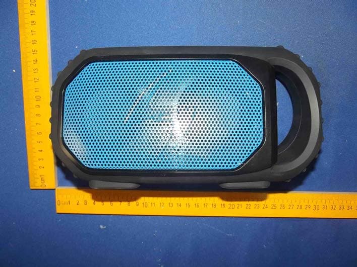
Click to zoom
Application Details
- Equipment Class
- DSS - Part 15 Spread Spectrum Transmitter
- Date of Grant
- Jul 27, 2014
- Application Purpose
- Original Equipment
- Date of Application
- Jul 27, 2014
- Equipment Note
- ECOSTONE
- Frequency Range
- 2402.00000000 - 2480.00000000
- Company
- NEO-TELECOM CORPORATION
- Country
- South Korea
Documents & Files
Document Text
Text extracted from the exhibit documents filed with the FCC. Open a document above to read the original.
Users Manual
Quick Start USER GUIDE ECOSTONE Features & Operation Models: GDI-EGST700--710 QUICK START 1-2-3 STEP 1: Power ON your ECOSTONE STEP 2: SEARCH your Bluetooth Connection on your Smart-device STEP 3: PAIR & PLAY STANDBY ON/OFF BLUETOOTH SPEAKER VOLUME TRACK SELECTION PLAY PAUSE ANSWER LED FLASHLIGHT Quick Start USER GUIDE STEPS 1-2-3 Set Up Recommendations STEP 1 CHARGE your ECOSTONE Before you power on your ECOSTONE connect the USB Micro port to the USB cable and a power source to fully charge your ECOSTONE for best performance. NOTE: Before using your ECOSTONE for the first time, charge the unit until all 4 LED battery level indicators are solid green, indicating a full charge. Typically approximately 3 hours of charging is required from a low to a FULL charge. Power source options include the USB connection to your computer or a power outlet using a USB to AC power adapter. Recommend always using the USB cable included with your ECOSTONE. RECOMMENDATION: always use the USB cable included with your ECOSTONE STEP 2 Power ON, Battery & LED Status Indicators Once fully charged, press the STANDBY POWER button on the top of your ECOSTONE. You will see the green LED light & you will hear an ascending bell tone when powering ON. IMPORTANT: be sure the MAIN POWER switch located in the back compartment under the cap is set in the UPPER ON position. IF the switch is in the LOWER OFF position your ECOSTONE will not be able to turn ON using the Standby button. The LED battery level indicators are located on the top of the unit. Each bar represents 25%, 4 full LED’s indicates a FULL charge AUDIO playback time over Bluetooth connection is approx. 12 hours at 75% max. volume Quick Start USER GUIDE STEP 3 Bluetooth pairing & your Audio Connecting with Bluetooth: connect to your Smart-device & play AUDIO When your ECOSTONE is turned ON the blue LED light on the top panel will flash rapidly indicating the unit is ready to pair. Turn on Bluetooth on your Bluetooth device (Smart-device) and set the device in pairing mode. Available Bluetooth connections shall appear. Select the ECOXGEAR speaker from the list of discovered devices on your Bluetooth device. Wait for a few seconds until the connection is completed. When the ECOXGEAR selection is made and the Bluetooth connection is completed your ECOSTONE announces: “Bluetooth connected” Once connected, select and play your desired audio NOTE: IF the LED is not flashing or if you wish to place your ECOSTONE in pairing mode, press and release the Bluetooth button on the top panel. Your ECOSTONE shall announce “pairing ready” when ready to pair to a new device. NOTE: Your ECOSTONE shall sync & wirelessly pair with most Bluetooth enabled devices. The unit remembers the last device paired and will automatically search for previous connections when the speaker is turned ON or when a device comes back into Bluetooth range. If a connection is lost due to range, the speaker will look to re-establish that connection. IF Bluetooth is turned OFF on your Smart-device, the ECOSTONE will not automatically look for the device. RECOMMENDATION: IF you are not familiar with Bluetooth pairing for your Smartphone or other Smart-device refer to the User Guide for your Smartphone to learn how to add and pair a new device (ECOSTONE for instance) to your Smartphone using Bluetooth. NOTE: Bluetooth Pairing & Connections - Once paired, should you have an issue switching between Bluetooth connections between devices, open the Bluetooth Section within the device currently connected to the ECOSTONE and delete the Bluetooth connection. The ECOSTONE will then be available to pair & connect to an alternate Bluetooth enabled Smartphone / Audio Device Quick Start USER GUIDE Control Buttons & Connections, Functions & Feature STANDBY ON / OFF PRESS the STANDBY POWER button to turn the ECOSTONE ON/OFF. When turned OFF the ECOSTONE remains in STANDBY POWER mode. IMPORTANT: Standby Power function will NOT operate when the MASTER POWER is set OFF. Master Power Switch on the back panel must be set ON for Standby & your ECOSTONE to operate. BLUETOOTH When turned ON, the ECOSTONE will power on and search for your Bluetooth. Refer to STEP 3 for details SPEAKER VOLUME PRESS - to decrease the volume & PRESS + to increase the volume NOTE: Some Bluetooth devices may require they are manually set at max. for max. level audio Your ECOSTONE will beep to indicate when the + button is pressed and maximum volume setting is reached TRACK SELECTION PRESS < for previous track selection & PRESS > to advance the track selection PLAY PAUSE ANSWER PRESS button once to PAUSE & PLAY song tracks and to ANSWER mobile CALLS LED FLASHLIGHT PRESS the LED button once to turn ON the flashlight. PRESS a second time to turn OFF TOP PANEL [on the top] Quick Start USER GUIDE To access the connections TURN the cap to the LEFT so the cap’s arrow point lines up with “UNLOCKED” along the back edge of the unit. STEP 1: Select “UNLOCKED” STEP 2: Open Cap Step 3: Access Connections BACK PANEL [under the Cap] Master Power Switch & Connections Quick Start USER GUIDE ON OFF MASTER POWER MASTER POWER ECOSTONE has a separate Master Power Switch and a Standby Button. The Switch MUST be set to the ON position to power your ECOSTONE. Once the Switch is set to ON, use the Standby Button located on the top panel to turn the unit ON/OFF NOTE: When not in use for extended periods, turn the MASTER POWER OFF to preserve battery life. IMPORTANT: STANDBY POWER function will NOT operate when the MASTER POWER is set OFF OUTPUT 5V 1A USB OUTPUT Connect your devices’ USB cable to connect to the USB OUTPUT (5V...1A) connection in order to charge your device. Connect to the USB OUTPUT port to charge your personal device. Use the USB cable included with your personal device. NOTE: Charging rates are similar to the charging rate when connected to the USB of a desktop PC. Typical charge time is approx. 3hrs from low to full for most Smartphones however char…
Text truncated - open the document above for the full version.
Cover Letter(s)
SCS-F18: Project and Product Certification Representative Authorization Letter Page 1 of 2 Rev 4.0 775 Montague Expressway Milpitas, CA 95035 Tel: 408-526-1188 Fax: 408-526-1088 Email: [email protected] Project and Product Certification Representative Authorization Letter Reason for Amendment (current / obsolete) Revision History Approved Date FromTo Initial Release (obsolete)1.01.0Nov-14-2006 Revised wording (obsolete)1.02.0Sept–25-2007 Updated company template (obsolete)2.03.0Jan-31-2012 Updated letter information (current)3.04.0May-23-2014 SCS-F18: Project and Product Certification Representative Authorization Letter Page 2 of 2 Rev 4.0 (NEO-TELECOM CORPORATION) (2014-07-21) To: SIEMIC, INC. 775 Montague Expressway, Milpitas, CA 95035 USA Dear Sir/Madam, Re: Product Certification Representative Authorization Letter We, ____NEO-TELECOM CORPORATION____hereby authorize SIEMIC, Inc. to act as a Certification Body for certifying for the following project(s): Product description: ECOSTONE Model name: GDI-EGST700, GDI-EGST701, GDI-EGST702, GDI-EGST703, GDI- EGST704, GDI-EGST705, GDI-EGST706, GDI-EGST707, GDI-EGST708, GDI- EGST709, GDI-EGST710 FCC ID: WYHGDI-EGST700 Sincerely, Client’s signature Mickey Jang / Engineer Company Name: NEO-TELECOM CORPORATION Address: 7/F, 674-24, Anyang Dong, Manan Gu, Anyang City, Kyunggi Do, 430-831, South Korea Tel: 82-31-448-4265 Email: [email protected]
Cover Letter(s)
SCS-F19: Confidentiality Request LetterPage 1 of 2 Rev 3.0 775 Montague Expressway Milpitas, CA 95035 Tel: 408-526-1188 Fax: 408-526-1088 Email: [email protected] Confidentiality Request Letter Reason for Amendment (current / obsolete) Revision History Approved Date FromTo Initial Release (obsolete)1.01.0Nov-14-2006 Adding CFR 2.459 (obsolete)1.02.0August – 11 - 2008 Updated company template & Added text box (current) 2.03.0Jan-31-2012 SCS-F19: Confidentiality Request LetterPage 2 of 2 Rev 3.0 (NEO-TELECOM CORPORATION) (2014-07-21) To: Federal Communications Commission Authorization and Evaluation Division 7435 Oakland Mills Road Columbia, MD Subject:Permanent Confidentiality Requestfor FCC ID:WYHGDI-EGST700 We hereby request confidential treatment of information accompanying this application as outlined below: -Block Diagram -Schematics -Operational Description The above materials contain trade secrets and proprietary information not customarily released to the public. The public disclosure of these materials may be harmful to the applicant and provide unjustified benefits to its competitors. The applicant understands that pursuant to Section 0.457 & 0.459 of the Rules, disclosure of this application and all accompanying documentation will not be made before the date of the Grant for this application. Sincerely, Mickey Jang / Engineer Company Name: NEO-TELECOM CORPORATION Address: 7/F, 674-24, Anyang Dong, Manan Gu, Anyang City, Kyunggi Do, 430- 831, South Korea Tel: 82-31-448-4265 Email: [email protected]
Cover Letter(s)
NEO-TELECOM CORPORATION Declaration on Model Differences We, NEO-TELECOM CORPORATION 7/F, 674-24, Anyang Dong, Manan Gu, Anyang City, Kyunggi Do, 430-831, South Korea Declare that the following product(s): Product Name:ECOSTONE Model Number:GDI-EGST700, GDI-EGST701, GDI-EGST702, GDI-EGST703, GDI- EGST704, GDI-EGST705, GDI-EGST706, GDI-EGST707, GDI-EGST708, GDI-EGST709, GDI-EGST710 FCC ID:WYHGDI-EGST700 Utilize the identical circuit design, PCB layout, shielding and interface with (GDI-EGST700), only the appearance and model number are difference. Therefore this application can be regarded as identical in performance to the submitted test sample. The manufacturer would take all the responsibilities for the above product(s). For and on behalf of Anyang City, Kyunggi Do, South Korea Authorized personLocation Name:Mickey Jang Position:Engineer Date of issue:2014-07-21 *I hereby declare that I am entitled to sign on behalf of the applicant and that the information supplied is correct and complete.
External Photos
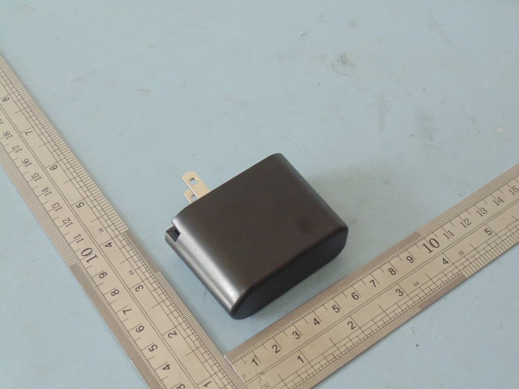
Figure 1 The EUT-Overall View Figure 2 The EUT-Top View Figure 3 The EUT-Bottom View Figure 4 The EUT-Front View Figure 5 The EUT-Back View Figure 6 The EUT-Right View Figure 7 The EUT-Left View
ID Label/Location Info
Product Name:ECOSTONE Model No.:GDI-EGST700 FCC ID:WYHGDI-EGST700 This device complies with Part 15 of the FCC Rules. Operation is subject to the following two conditions: (1) This device may not cause harmful interference, and (2) This device must accept any interference received, including interference that may cause undesired operation.
ID Label/Location Info
Label Location On EUT
Internal Photos
Figure 8 The EUT-Inside View Figure 9 PCB of the EUT-Front View Figure 10 PCB of the Module View Figure 11 PCB of the EUT-Back View Figure 12 PCB of the EUT-Front View Figure 13 PCB of the EUT-Front View
RF Exposure Info
MPE EVALUATION Model Name: ECOSTONE Model No.: GDI-EGST700, GDI-EGST701, GDI-EGST702, GDI-EGST703, GDI-EGST704, GDI-EGST705, GDI-EGST706, GDI-EGST707, GDI-EGST708, GDI-EGST709, GDI-EGST710 FCC ID:WYHGDI-EGST700 Limits for Maximum Permissible Exposure(MPE) Frequency Range(MHz) Electric Field Strength(V/m) Magnetic Field Strength(A/m) Power Density(mW/cm 2 ) Average Time (A) Limits for Occupational/Control Exposures 300-1500----F/3006 1500-100000----56 (B) Limits for General Population/Uncontrol Exposures 300-1500----F/15006 1500-100000----130 transmission formula: Pd=(Pout*G)\(4*pi*R2) Where Pd= Power density in mW/cm 2 Pout=output power to antenna in mW G= gain of antenna in linear scale Pi=3.1416 R= distance between observation point and center of the radiator in cm Pd the limit of MPE, 1mW/cm2. If we know the maximum gain of the antenna and total power input to the antenna, through the calculation, we willknow the distance where the MPE limit is reached. Measurement Result Channel Frequency (MHz) Output Peak power (mW) Antenna Gain (dBi) Power density at 20cm (mW/ cm 2 ) Power density Limits (mW/cm 2 ) Modulation 24021.1402.268e-41GFSK 24412.1604.297e-41GFSK 24802.1304.237e-41GFSK 2402 0.83 0 1.651e-4 1 π /4DQPSK 2441 1.82 0 3.621e-4 1 π/4DQPSK 2480 1.54 0 3.064e-4 1 π /4DQPSK 2402 0.83 0 1.651e-4 1 8DPSK 2441 1.82 0 3.621e-4 1 8DPSK 2480 1.54 0 3.064e-4 1 8DPSK
Test Report
Shenzhen Anbotek Compliance Laboratory Limited FCC ID: WYHGDI-EGST700 Page 1 of 57 Report No.: R011406530E Shenzhen Anbotek Compliance Laboratory Limited Tel:(86)755-26066544 Fax:(86)755-26014772 www.anbotek.com FCC TEST REPORT for NEO-TELECOM CORPORATION ECOSTONE Model No.: GDI-EGST700, GDI-EGST701, GDI-EGST702, GDI-EGST703, GDI-EGST704,GDI-EGST705, GDI-EGST706, GDI-EGST707, GDI-EGST708, GDI-EGST709, GDI-EGST710 Report Number:R011406530E Date of Test:Jul. 01 ~18, 2014 Date of Report:Jul. 21, 2014 Prepared fo r:NEO-TELECOM CORPORATION Address:7/F, 674-24, Anyang Dong, Manan Gu, Anyang City, Kyunggi Do, 430-831, South Korea Prepared B y:Shenzhen Anbotek Compliance LaboratoryLimited Address:1/F., Building 1, SEC Industrial Park, No.0409 Qianhai Road, Nanshan District, Shenzhen, Guangdong, China Tel: (86) 755-26066544 Fax: (86) 755-26014772 Shenzhen Anbotek Compliance Laboratory Limited FCC ID: WYHGDI-EGST700 Page 2 of 57 Report No.: R011406530E Shenzhen Anbotek Compliance Laboratory Limited Tel:(86)755-26066544 Fax:(86)755-26014772 www.anbotek.com TABLE OF CONTENTS Description Page Test Report 1. GENERAL INFORMATION......................................................................................................5 1.1 Description of Device (EUT).................................................................................................................5 1.2 Auxiliary Equipment Used during Test................................................................................................. 6 1.3 Description of Test Facility................................................................................................................... 6 1.4 Measurement Uncertainty......................................................................................................................6 2. TEST PROCEDURE....................................................................................................................7 3. CONDUCTED EMISSION......................................................................................................... 8 3.1 Block Diagram of Test Setup.................................................................................................................8 3.2 Power Line Conducted Emission Measurement Limits (15.207)..........................................................8 3.3 Configuration of EUT on Measurement................................................................................................ 8 3.4 Operating Condition of EUT................................................................................................................. 8 3.5 Test Procedure....................................................................................................................................... 9 3.6 Power Line Conducted Emission Measurement Results....................................................................... 9 4. RADIATION INTERFERENCE.............................................................................................. 12 4.1 Requirements (15.247, 15.209):...........................................................................................................12 4.2 Test Procedure..................................................................................................................................... 12 4.3 Test Configuration............................................................................................................................... 13 4.4 Test Results..........................................................................................................................................14 5. CHANNEL SEPARATION TEST............................................................................................23 5.1 Measurement Procedure.......................................................................................................................23 5.2 Test SET-UP........................................................................................................................................ 23 5.3 Test Equipment.................................................................................................................................... 23 5.4 Test Results..........................................................................................................................................24 6. 20DB BANDWIDTH TEST.......................................................................................................28 6.1 Measurement Procedure.......................................................................................................................28 6.2 Test SET-UP........................................................................................................................................ 28 6.3 Test Equipment.................................................................................................................................... 28 6.4 Test Results..........................................................................................................................................28 7. QUANTITY OF HOPPING CHANNEL TEST...................................................................... 32 7.1 Measurement Procedure.......................................................................................................................32 7.2 Test SET-UP........................................................................................................................................ 32 7.3 Test Equipment.................................................................................................................................... 32 7.4 Test Results..........................................................................................................................................32 8. DWELL TIME TEST................................................................................................................34 8.1 Measurement Proced…
Text truncated - open the document above for the full version.
Test Setup Photos
1 Photo of Power Line Conducted Emission Measurement 2 Photo of Radiation Emission Test
Contact Information
Applicant
Mickey Jang(Engineer)
Test Firm
Shenzhen Anbotek Compliance Laboratory LimitedDaniel zhu
[email protected]86-755-26014771
Technical Specifications
| # | Rule Parts | Frequency Range | Power Output |
|---|---|---|---|
| 1 | 15C | 2.40 GHz - 2.48 GHz | 2.16 mW |
Other Applications from NEO-TELECOM CORPORATION
WYHGDI-EXCBN200
Aug 30, 2015ECOCARBON
Equipment Class
DSS - Part 15 Spread Spectrum TransmitterWYHGDI-SXTTR2
Jan 08, 2015Sound Station
Equipment Class
DTS - Digital Transmission System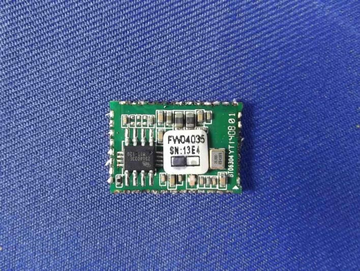
WYHFW3817-40
Jul 31, 2014ECOSTONE
Equipment Class
DSS - Part 15 Spread Spectrum Transmitter