X2LAEPEL-1WIRELESS MICROPHONE
AEPEL INC.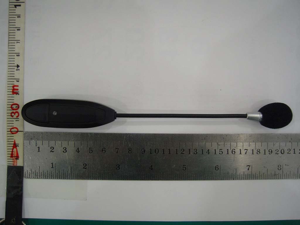
Click to zoom
Application Details
- Equipment Class
- DSS - Part 15 Spread Spectrum Transmitter
- Date of Grant
- Jan 31, 2010
- Application Purpose
- Original Equipment
- Date of Application
- Jan 28, 2010
- Equipment Note
- WIRELESS MICROPHONE
- Frequency Range
- 2402.00000000 - 2480.00000000
- Company
- AEPEL INC.
- Country
- South Korea
Documents & Files
Document Text
Text extracted from the exhibit documents filed with the FCC. Open a document above to read the original.
ID Label/Location Info
FCC Label 1. FCC Label Drawing 2. FCC Label Location AEPEL INC. Model : FC-730M FCC ID : X2LAEPEL-1 Made in Korea This device complies with part 15 of the FCC Rules. Operation is subject to the following two conditions : (1) This device may not cause harmful interference, and (2) This device must accept any interference received, including interference that may cause undesired operation.
Internal Photos
Internal view of EUT View of Main PCB View of Speaker View of Battery
Parts List/Tune Up Info
1. Outline Wireless audio transmitter & receiver that use 2.4GHz wide banded, frequency range is 2402MHz~248 MHz, transmitter output is 0dBm, i.e. 1mW. This has 15MHz of frequency hopping extent per one channel. 2. Schematic flow chart - transmitter 2.1 Microphone (condensor microphone) It is input section to be inputed audio signal. It’s operating voltage is 1.5V~3.0V, and makes microphone act by supplying 2.2V. 2.2 CODEC It supplies Mic Bias voltage (from input section) and converts inputed signal into ADC (analog digital converting) and do sampling 2.4KHz. 2.3 CPU It detects voltage of internal bettery and codec's various functions. Also, controls NRF2401AG RF IC (made by Nordic company) and WM8731LEF/R IC (made by CODEC Wolfson). 2.4 LED DISPLAY After sending voltage data (from voltage detect section) to CPU, controls LED display by using data transfered. Also, send fairing data sended from NRF2401AG RF IC (made by Nordic company) to CPU, controls LED display by using data transferred. 2.5 MODEM Data (from Mic input section) is inputted into CODEC, and digital ADC data (inputted into CPU) is transffered to internal antena through RF IC and then data is transffered to fixed frequency. 3. Schematic flow chart -Receiver 3.1 Internal antena Receives transmited frequency and transmits to MODEM. 3.2 MODEM Transmits data received by antena to CPU. 3.3 CPU Transmits data (received by MODEM) to CODEC and controls surrounding various circuit. 3.4 CODEC It does DAC (Digital analog converting) by using received data from CPU, transfer audio data (inputted from Wire Mic & Audio External Input) to CPU or Amplifier section. 3.5 Volume UP/DOWN KEY Data (produced by controling key) is transferred into CPU, CPU controls LCD DISPLAY circuit and signal gain of CODEC. 3.6 AMP Amplifiers audio signal (inputted from CODEC) and runs speaker. It is fixed gain method and analog BTL alplifier, not digital amplifier. 4. Internal Battery 4.1 Tranmitter battry Transmitter battery is a Rithium polymer battery, which has 3.3V ~4.2V voltage range and 240mAh of capacity. It's charging fills up 120mAh per hour and external chrger is equiped with CPU. Current consumption value is 3.5mAh per hour. 4.2 Receiver battery Receiver batteries are connected in serial, have 6.6V ~ 8.4V of voltage range , 2000mAh capacity. External charger is equipped with CPU, chrging fills up 800mAh per hour. Current consumtion value is 200mAh per hour.
Test Report
Report Number : KSQ-FCC091218FCC ID : X2LAEPEL-1 Page 2 /35 TABLE OF CONTENTS 1. GENERAL INFORMATION....................................................................................................................3 1.1. Applicant(client)...................................................................................................................................3 1.2. Equipment(EUT)..................................................................................................................................3 1.3. Testing Laboratory ...............................................................................................................................4 2. SUMMARY OF TEST RESULTS............................................................................................................5 3. MEASUREMENT & RESULT.................................................................................................................6 3.1. ANTENNA REQUIREMENT..............................................................................................................6 3.2. 20dB BANDWIDTH..........................................................................................................................7 3.3. MAXIMUM PEAK OUTPUT POWER..........................................................................................10 3.4. CARRIER FREQUENCY SEPARATION.........................................................................................13 3.5. NUMBER OF HOPPING CHANNELS.............................................................................................15 3.6. DWELL TIME....................................................................................................................................17 3.7. SPURIOUS EMISSIONS, BAND EDGE, AND RESTRICTED BANDS.........................................20 3.8. RECEIVERSPURIOUS EMISSIONS...............................................................................................31 3.9. RF EXPOSURE..................................................................................................................................33 4. TEST EQUIPMENTS..............................................................................................................................34 ** APPENDIXS 1. EUT photo Report Number : KSQ-FCC091218FCC ID : X2LAEPEL-1 Page 3 /35 1. GENERAL INFORMATION 1.1. Applicant (Client) Name AEPEL INC. Address 445-13, Geumsung-ri, Tanhyeon-myeon, Paju-City, Gyeonggi-do, Korea Contact Person Sung-ho, Yoo Telephone No. +82-31-945-5830 Facsimile No. +82-31-945-5832 E-mail address [email protected] 1.2. Equipment (EUT) Type of equipmentWireless MicroPhone Model NameFC-730M FCC IDX2LAEPEL-1 Frequency Band2402 ~ 2480 MHz Type of ModulationGFSK Numberof Channels79 channels Antenna Gain2dBi Function TypeTransceiver Power SourceInput DC 9V (Adapter) Output DC 4.2V (Li-Ion battery) ManufacturerName AEPEL INC. ManufacturerAddress 445-13, Geumsung-ri, Tanhyeon-myeon, Paju-City, Gyeonggi-do, Korea Report Number : KSQ-FCC091218FCC ID : X2LAEPEL-1 Page 4 /35 1.3. Testing Laboratory Testing Place Korea Standard Quality Laboratories Test EngineerYoung Ryul, Jo Telephone number+82-31-356-7333 Facsimile number+82-31-356-7303 E-mail [email protected] Report Number : KSQ-FCC091218FCC ID : X2LAEPEL-1 Page 5 /35 2. SUMMARY OF TEST RESULTS 2.1. Testing performed for:Wireless MicroPhone 2.2. Equipment UnderTest :FC-730M 2.3. Receipt of Test Sample :November 30, 2009 2.4. Test Start Date :December 01, 2009 2.5. Test End Date :December 02, 2009 The following table represents the list of measurements required under the FCC CFR47 Part 15.207, 15.247, 15.209 Note 1 : Test results reported in this document relate only to the items tested Note 2 : The required tests demonstrated compliance as per client declaration of test configuration, monitoring methodology and associated pass/fail criteria Note 3 : Test results apply only to the item(s) tested * Modifications required for compliance No modifications were implemented by KSQ. All results in this report pertain to the un-modified sample provided to KSQ. RequirementCFR 47 SectionReport SectionTest Result Antenna Requirement15.203, 15.247(b)(4)3.1PASS 20dB Bandwidth15.247(a)(1)3.2PASS Maximum Peak Output Power15.247(b)(1), (4)3.3PASS Carrier Frequency Separation15.247(a)(1)3.4PASS Number of Hopping Channels 15.247(a)(iii), 15.247(b)(1) 3.5PASS Dwell Time15.247(a)(iii)3.6PASS Spurious Emission, Band Edge, and Restricted bands 15.247(d), 15.205(a), 15.209(a)3.7PASS Receiver Spurious Emissions-3.8PASS RF Exposure15.247(i), 1.1307(b)(1)3.9PASS Report Number : KSQ-FCC091218FCC ID : X2LAEPEL-1 Page 6 /35 3. Measurement & Results 3.1 ANTENNA REQUIREMENT 3.1.1 Regulation According to §15.203, an intentional radiator shall be designed to ensure that no antenna other than that furnished by the responsible party shall be used with the device. The use of a permanently attached antenna or of an antenna that uses a unique coupling to the intentional radiator shall be considered sufficient to comply with the provisions of this Section. The manufacturer may design the unit so that a broken antenna can be replaced by the user, but the use of a standard antenna jack or electrical connector is prohibited. And according to §15.247(b)(4), the conducted output power limit specified in paragraph (b) of this section is based on the use of antennas with directional gains that do not exceed 6 dBi. Except as shown in paragraph (c) of this section, if transmitting antennas of directional gain greater than 6 dBi are used, the conducted output power from the intentional radiator shall be reduced below the stated values in paragraphs (b)(1), (b)(2), and (b)(3) of this section, as appropriate, by the amount in dB that the directional gain of the antenna exceeds 6 dBi. 3.1.2 Result :PASS The transmitter has an integral Chip antenna. The directional gain of the antenna is 2.0 dBi. Report Number : KSQ-FCC091218F…
Text truncated - open the document above for the full version.
Contact Information
Applicant
Sung-Ho Yoo
Test Firm
Korea Standard Quality LaboratoriesSung-goo Kim
Technical Specifications
| # | Rule Parts | Frequency Range | Power Output |
|---|---|---|---|
| 1 | 15C | 2.40 GHz - 2.48 GHz | 300.00 µW |
Other Applications from AEPEL INC.
X2LAEPEL-2
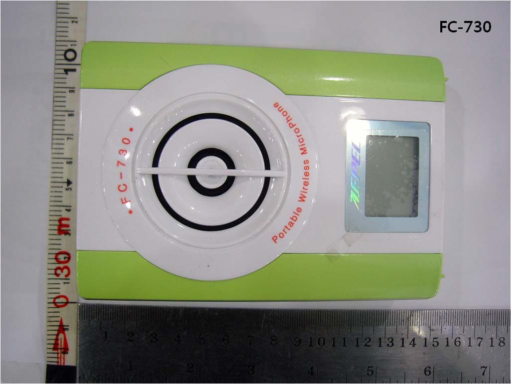
Jan 28, 2010WIRELESS SPEAKER
Equipment Class
DSS - Part 15 Spread Spectrum Transmitter