X2LAEPEL-2WIRELESS SPEAKER
AEPEL INC.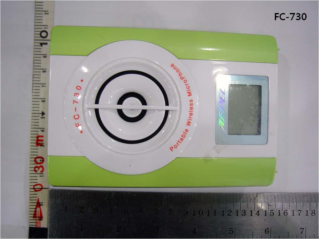
Click to zoom
Application Details
- Equipment Class
- DSS - Part 15 Spread Spectrum Transmitter
- Date of Grant
- Jan 28, 2010
- Application Purpose
- Original Equipment
- Date of Application
- Jan 27, 2010
- Equipment Note
- WIRELESS SPEAKER
- Frequency Range
- 2402.00000000 - 2480.00000000
- Company
- AEPEL INC.
- Country
- South Korea
Documents & Files
Document Text
Text extracted from the exhibit documents filed with the FCC. Open a document above to read the original.
Users Manual
1 PROFESSIONAL SOUND SYSTEM 1 www.aepel.co. kr AIS contact : 445-13, Geumseung-ri, Tanhyeonm-yeon, Paju city, Gyeonggi Province, We will consult its usage and AIS with our fast kindness and friendly smiles. AEPEL Inc., the professional and special manufacturer of the Audio Products has commercialized to launch this product through over 2 years R&D. We have achieved this product through a lot of trial and error same as another wireless devices products, and done our every efforts to return a great pleasure to our consumers. This device of FC-730 has a small built-in amplifier to make the sound volume and rich, the noise to be minimized for the protection of the customers voice. It is a sharp design and compact but rich volume for the easy carrying. It is the multi-purpose loudspeaker which can be used as compatible with wire and wireless. 3 FEATURE OF THE PRODUCT Rather than the analog to the digital circuit design, it is lightweight and excellently durable. With the sharp design, it could add the customers'satisfaction. With the design of the Digital modulation, the clarity of voice is clear and the influence of the signal mixture is very few. Using the Lithium-ion batteries used in cell phone use, its weight becomes minimized. We are proud of its fast charge time. With the Special speakers using the neohdiyum mageuneteu it can excellently deliver the vivid original voice. Installing the LCD window in the center of the product, customers can easily recognize status of the volume, battery and the wireless action. With the an external input terminal, it can be used to connect to a computer or MP3. Its Wireless performance to overcome the disadvantages of regular wired microphone can be used conveniently. With the design of the super power saving, it can be used 10 hours or more. Just with the once charge. (Using the normal operation) PRODUCT COMPOSITION - Console Wireless Microphone Wireless microphone headset Wired microphone Neck hanger Y Adapter deluxe case bags Using manual SPECIFICATIONS f > Frequency response : 2402MHz-2480MHz Normal operation Temperature : -10 "C - 50°C Maximum Output : 20W Weigh t : 3009 External resistance : 48 Size (mm) : 88 (W) x 128 (H) x 25 (D) \ rl~~t AND FUNCTION I Volume adjustern I 1 volume adjusterCl \ 1 Wired microphone terminal 1 External input terminal (MP3, computers) 4 Program initialization I 1 Battery charge I HOW TO USE THE CONSOLE 1. Power Switch : ON I OFF, please push for two seconds. 2. Volume Adjustment : Press the button to the desired volume. 3. Charging socket : It is used to charge the product, be sure to use the rechargeable adapter. 4. LCD Window The battery indicator : It indicates the battery life. If decreased to the number of bar one, please charge. The volume indicator : As the volume bar increases, the voice volumes become increased. Function indicator : Using a wired microphone Using a wireless microphone Using an external device Battery indicator Operation mode of the external device T 4- AUX ~-'~~~;~Ode Microphone Indicating bar 'VIRELESS MICROPHONE I How to assemble a wireless microphont headset When the direction of the arrow is consistent with the , , , direction of the sound, it can be used as the ideal microphone sensitivity. In case of no communication with the console over 3 minutes, the power automatically turns off the wireless microphone to protect the battery d~harging terminall 4 Battery indicator I 4 Power button I HOW TO USE THE MICROPHONE 1. If the power switch on the body push slightly About two seconds, the LCD window will light on. 2. Using the wireless microphone, please push slightly the wireless microphone switch for about 2 seconds. 3. Using the wired microphone, please insert the wired microphone plug on the side of the console and set the switch of the console side to the wired use. 4. Connecting the External devices (MP3, CD), please set the switch of the console side to the external device. 5. Pushing the volume adjust switch of the console, please set the appropriate sound volume to fit the size. 6. If the red and green lamps flashes together on the display window in case of the battery exhausted, please recharge immediately. 7. Please turn off if not used. CAUTIONS 1. If the scale bar number of the battery becomes one on the LCD window, please charge together with the wireless microphone, 2. When charging, please ensure to use the adapter included in this product. 3. If the direction of the microphone is wrong, it may cause the Howling, so please use the microphone as possible as close to your mouth. 4. If used on the table or deck, it could be dropped by the Vibration, please put in the case to use. 5. If products out of order, please do not disassemble the product by yourself, please ensure to contact us. low to use the wireless microphone for the best sound quality 1. Using the headset connection In case of wearing the headset as combining a wireless microphone and the heads, when the microphone is far about Icm away from the lips to adjust the flexible part (wireless microphone stand), it can be uses as most rich sound volume. The red dot on the microphone is a orientation point. If the direction of the mouth is consistent with the direction of the orientation of the microphone, the rich volume could be performed. The personal portable microphone of the commercial product in the current market is always near to the console which is working, so directional microphone is used to minimize the Howling. The wire, wireless microphone of the AEPEL PHONE is also a directional microphone. The wireless microphone of the AEPEL PHONE has manufactured, assuming a headset used. The orientation of the microphone is little bit different from your normally using microphone. Therefore, if you use it as a regular microphone, the sound may be reduced significantly, because the passing angle of the sound is in-conformity. 2. How to check the wireless microphones operating state Green light : Operating normally connec…
Text truncated - open the document above for the full version.
ID Label/Location Info
FCC Label 1. FCC Label Drawing 2. FCC Label Location . AEPEL INC. Model : FC-730 FCC ID : X2LAEPEL-2 Made in Korea This device complies with part 15 of the FCC Rules. Operation is subject to the following two conditions : (1) This device may not cause harmful interference, and (2) This device must accept any interference received, including interference that may cause undesired operation.
Internal Photos
Internal view of EUT Internal view of EUT View of Main PCB View of LCD View of Speaker View of Battery View of Sponge
Parts List/Tune Up Info
1. Outline Wireless audio transmitter & receiver that use 2.4GHz wide banded, frequency range is 2402MHz~248 MHz, transmitter output is 0dBm, i.e. 1mW. This has 15MHz of frequency hopping extent per one channel. 2. Schematic flow chart - transmitter 2.1 Microphone (condensor microphone) It is input section to be inputed audio signal. It’s operating voltage is 1.5V~3.0V, and makes microphone act by supplying 2.2V. 2.2 CODEC It supplies Mic Bias voltage (from input section) and converts inputed signal into ADC (analog digital converting) and do sampling 2.4KHz. 2.3 CPU It detects voltage of internal bettery and codec's various functions. Also, controls NRF2401AG RF IC (made by Nordic company) and WM8731LEF/R IC (made by CODEC Wolfson). 2.4 LED DISPLAY After sending voltage data (from voltage detect section) to CPU, controls LED display by using data transfered. Also, send fairing data sended from NRF2401AG RF IC (made by Nordic company) to CPU, controls LED display by using data transferred. 2.5 MODEM Data (from Mic input section) is inputted into CODEC, and digital ADC data (inputted into CPU) is transffered to internal antena through RF IC and then data is transffered to fixed frequency. 3. Schematic flow chart -Receiver 3.1 Internal antena Receives transmited frequency and transmits to MODEM. 3.2 MODEM Transmits data received by antena to CPU. 3.3 CPU Transmits data (received by MODEM) to CODEC and controls surrounding various circuit. 3.4 CODEC It does DAC (Digital analog converting) by using received data from CPU, transfer audio data (inputted from Wire Mic & Audio External Input) to CPU or Amplifier section. 3.5 Volume UP/DOWN KEY Data (produced by controling key) is transferred into CPU, CPU controls LCD DISPLAY circuit and signal gain of CODEC. 3.6 AMP Amplifiers audio signal (inputted from CODEC) and runs speaker. It is fixed gain method and analog BTL alplifier, not digital amplifier. 4. Internal Battery 4.1 Tranmitter battry Transmitter battery is a Rithium polymer battery, which has 3.3V ~4.2V voltage range and 240mAh of capacity. It's charging fills up 120mAh per hour and external chrger is equiped with CPU. Current consumption value is 3.5mAh per hour. 4.2 Receiver battery Receiver batteries are connected in serial, have 6.6V ~ 8.4V of voltage range , 2000mAh capacity. External charger is equipped with CPU, chrging fills up 800mAh per hour. Current consumtion value is 200mAh per hour.
Test Report
Report Number : KSQ-FCC091219FCC ID : X2LAEPEL-2 Page 2 /35 TABLE OF CONTENTS 1. GENERAL INFORMATION....................................................................................................................3 1.1. Applicant(client)...................................................................................................................................3 1.2. Equipment(EUT)..................................................................................................................................3 1.3. Testing Laboratory ...............................................................................................................................4 2. SUMMARY OF TEST RESULTS............................................................................................................5 3. MEASUREMENT & RESULT.................................................................................................................6 3.1. ANTENNA REQUIREMENT..............................................................................................................6 3.2. 20dB BANDWIDTH..........................................................................................................................7 3.3. MAXIMUM PEAK OUTPUT POWER..........................................................................................10 3.4. CARRIER FREQUENCY SEPARATION.........................................................................................13 3.5. NUMBER OF HOPPING CHANNELS.............................................................................................15 3.6. DWELL TIME....................................................................................................................................17 3.7. SPURIOUS EMISSIONS, BAND EDGE, AND RESTRICTED BANDS.........................................20 3.8. RECEIVERSPURIOUS EMISSIONS...............................................................................................31 3.9. RF EXPOSURE..................................................................................................................................33 4. TEST EQUIPMENTS..............................................................................................................................34 ** APPENDIXS 1. EUT photo Report Number : KSQ-FCC091219FCC ID : X2LAEPEL-2 Page 3 /35 1. GENERAL INFORMATION 1.1. Applicant (Client) Name AEPEL INC. Address 445-13, Geumsung-ri, Tanhyeon-myeon, Paju-City, Gyeonggi-do, Korea Contact Person Sung-ho, Yoo Telephone No. +82-31-945-5830 Facsimile No. +82-31-945-5832 E-mail address [email protected] 1.2. Equipment (EUT) Type of equipmentWireless Speaker Model NameFC-730 FCC IDX2LAEPEL-2 Frequency Band2402 ~ 2480 MHz Type of ModulationGFSK Numberof Channels79 channels Antenna Gain2dBi Function TypeTransceiver Power SourceInput DC 9V (Adapter) Output DC 8.4V (Li-Ion battery) ManufacturerName AEPEL INC. ManufacturerAddress 445-13, Geumsung-ri, Tanhyeon-myeon, Paju-City, Gyeonggi-do, Korea Report Number : KSQ-FCC091219FCC ID : X2LAEPEL-2 Page 4 /35 1.3. Testing Laboratory Testing Place Korea Standard Quality Laboratories Test EngineerYoung Ryul, Jo Telephone number+82-31-356-7333 Facsimile number+82-31-356-7303 E-mail [email protected] Report Number : KSQ-FCC091219FCC ID : X2LAEPEL-2 Page 5 /35 2. SUMMARY OF TEST RESULTS 2.1. Testing performed for:Wireless Speaker 2.2. Equipment UnderTest :FC-730 2.3. Receipt of Test Sample :November 30, 2009 2.4. Test Start Date :December 01, 2009 2.5. Test End Date :December 02, 2009 The following table represents the list of measurements required under the FCC CFR47 Part 15.207, 15.247, 15.209 Note 1 : Test results reported in this document relate only to the items tested Note 2 : The required tests demonstrated compliance as per client declaration of test configuration, monitoring methodology and associated pass/fail criteria Note 3 : Test results apply only to the item(s) tested * Modifications required for compliance No modifications were implemented by KSQ. All results in this report pertain to the un-modified sample provided to KSQ. RequirementCFR 47 SectionReport SectionTest Result Antenna Requirement15.203, 15.247(b)(4)3.1PASS 20dB Bandwidth15.247(a)(1)3.2PASS Maximum Peak Output Power15.247(b)(1), (4)3.3PASS Carrier Frequency Separation15.247(a)(1)3.4PASS Number of Hopping Channels 15.247(a)(iii), 15.247(b)(1) 3.5PASS Dwell Time15.247(a)(iii)3.6PASS Spurious Emission, Band Edge, and Restricted bands 15.247(d), 15.205(a), 15.209(a)3.7PASS Receiver Spurious Emissions-3.8PASS RF Exposure15.247(i), 1.1307(b)(1)3.9PASS Report Number : KSQ-FCC091219FCC ID : X2LAEPEL-2 Page 6 /35 3.MEASUREMENT & RESULT 3.1 ANTENNA REQUIREMENT 3.1.1 Regulation According to §15.203, an intentional radiator shall be designed to ensure that no antenna other than that furnished by the responsible party shall be used with the device. The use of a permanently attached antenna or of an antenna that uses a unique coupling to the intentional radiator shall be considered sufficient to comply with the provisions of this Section. The manufacturer may design the unit so that a broken antenna can be replaced by the user, but the use of a standard antenna jack or electrical connector is prohibited. And according to §15.247(b)(4), the conducted output power limit specified in paragraph (b) of this section is based on the use of antennas with directional gains that do not exceed 6 dBi. Except as shown in paragraph (c) of this section, if transmitting antennas of directional gain greater than 6 dBi are used, the conducted output power from the intentional radiator shall be reduced below the stated values in paragraphs (b)(1), (b)(2), and (b)(3) of this section, as appropriate, by the amount in dB that the directional gain of the antenna exceeds 6 dBi. 3.1.2 Result :PASS The transmitter has an integral Chip antenna. The directional gain of the antenna is 2.0 dBi. Report Number : KSQ-FCC091219FCC ID : X2…
Text truncated - open the document above for the full version.
Contact Information
Applicant
Sung-Ho Yoo
Test Firm
Korea Standard Quality LaboratoriesSung-goo Kim
Technical Specifications
| # | Rule Parts | Frequency Range | Power Output |
|---|---|---|---|
| 1 | 15C | 2.40 GHz - 2.48 GHz | 200.00 µW |
Other Applications from AEPEL INC.
X2LAEPEL-1
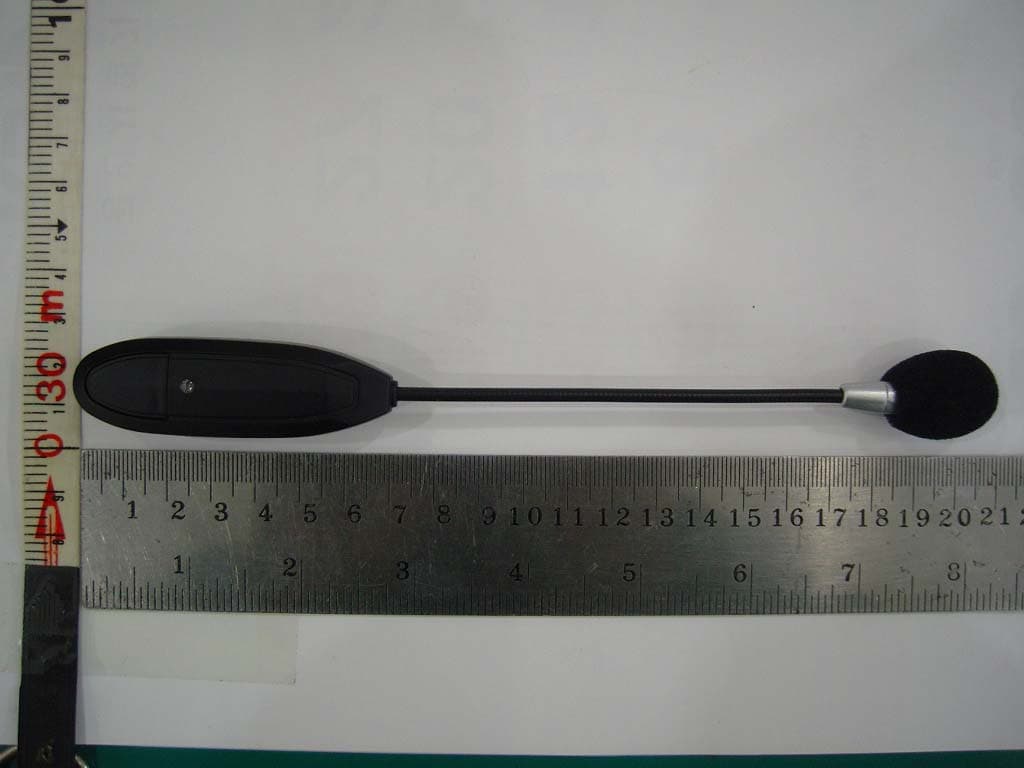
Jan 31, 2010WIRELESS MICROPHONE
Equipment Class
DSS - Part 15 Spread Spectrum Transmitter