X2PAMPRF-1RF POWER AMPLIFIER WITH CERTIFIED TRANSCEIVER
Cooper Notification, Inc.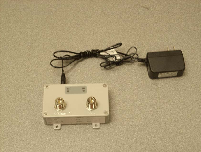
Click to zoom
Application Details
- Equipment Class
- DTS - Digital Transmission System
- Date of Grant
- Jan 14, 2013
- Application Purpose
- Original Equipment
- Date of Application
- Jan 14, 2013
- Equipment Note
- RF POWER AMPLIFIER WITH CERTIFIED TRANSCEIVER
- Frequency Range
- 2401.00000000 - 2481.00000000
- Company
- Cooper Notification, Inc.
- Country
- United States
Documents & Files
Document Text
Text extracted from the exhibit documents filed with the FCC. Open a document above to read the original.
Users Manual
Installation Instruction Sheet: AMP-RF-1 P/N P10-00071-A 1 of 7 INSTALLATION INSTRUCTIONS Installation Instruction Sheet: AMP-RF-1 Instruction: Model AMP-RF-1 Applicability: Applies to WAVES CRLU and TRX Installs only Part Number: P10-00071 Date: December 4, 2012 1. Purpose This sheet provides the specifications of Indoor Amplifier model AMP-RF-1 along with detailed instructions to install the 1 Watt, 2.4 GHz amplifier into a WAVES s ystem using either a CRLU-201 or a TRX-401. Model AMP-RF-1 is intended for indoor installations that require additional output power to compensate for long transmission runs between the CRLU/TRX and the antenna. 2. Cautions and Warnings The following are specific Cautions and Warnings that must be followed when installing or operating equipment. • Please read all instructions before attempting to install any equipment. Failure to follow directions can cause bodily injury and/or damage to the equipment. • Ensure that precautionary measures are employed to prevent applying power to equipment at any time maintenance work is in progress. • Do not make any unauthorized alterations to equipment or components. Changes or modifications not expressly approved by Cooper Notification can result in damage to the equipment and will void the warranty. • When working near electricity do not use metal rules, flashlights, metallic pencils, or any other object having exposed conducting material. • Ensure all electrical connections are secure before applying power to a unit. Failure to secure connections may cause an electrical arc resulting in physical shock or damage to the equipment. • Do not touch electronic components with wet hands. • When possible, avoid installing equipment during severe or wet conditions. Handling equipment with wet hands may cause slippage resulting in bodily injury and/or damage to equipment. • Comply with all electrical codes per the local authority having jurisdiction. 3. Tools Required tools and equipment needed to install the amplifier shall be determined by qualified service personnel. Specifications Installation Instruction Sheet: AMP-RF-1 P/N P10-00071 Rev A INSTALLATION INSTRUCTIONS 2 of 3 4. Specifications General Specifications of the AMP-RF-1 are listed below in Table 1. Table 1 General Specifications Spec RF Amplifier Model AMP-RF-1 Transmit Power Receive Gain Frequency Max Input Power Min Input Power Dimensions Weight Amplifier Current Draw Amplifier Supply Voltage Class II Power Supply Voltage Rating Temperature Input/Output Connectors Compatible Access Points 1 Watt (30 dBm) 15 dB nominal 2.4 – 2.5 GHz 100 mW (20 dBm) 3 mW (5dBm) 4.5 x 2.5 x 1.3 in (117 x 64 x 33 mm) .68 lbs (.30 Kg) 0.8 A @12VDC 9 - 12 VDC 110-240 VAC, 50/60 Hz 0 to 49 C (32 to 120 F) Indoor Use Only N-Type Female CRLU-201 and TRX-401 Series only FCC WARNINGS 1. Modifications are not allowed to the amplifier or support equipment. 2. Any modification could void the User’s authority to operate the equipment. 3. Antenna placement must be no less than 1 meter from any potential point of human contact or exposure. 4. The AMP-RF-1 amplifier can only be used with access point FCC ID: X2PAMPRF-1. Access point FCC ID: X2PAMPRF-1 consists of one of the antennas listed in this manual and an access point model CRLU-201 or TRX- 401. Refer to Section 7 Labeling Instructions, for special access point labeling instructions. AMP-RF-1 Outline Drawings Installation Instruction Sheet: AMP-RF-1 P/N P10-00071 Rev A INSTALLATION INSTRUCTIONS 3 of 3 5. AMP-RF-1 Outline Drawings Figures 1 and 2 below provide outline drawings of the Front, Side, Rear, and Top views of the amplifier. Figure 1 AMP-RF-1 Front/Side/Rear Views Figure 2 AMP-RF-1 Top View/DC Power Connection 6. Installation The installation of the power amplifier shall be conducted by qualified service personnel. To ensure compliance with mandatory codes and standards all instructions listed in this document should be followed. For installations other than military applications, the use of the amplifier must meet EIRP (Effective Isotropic Radiated Power) requirements mandated by the FCC. This section provides the basic information required to define and calculate EIRP. Each installation is unique therefore it is the responsibility of the service personnel to ensure proper installation. 1. Calculate Transmission Line Loss including connector loss. Refer to section 6.1.1 for typical loss when using LMR coax cable. 2. Identify the type of antenna in use. Refer to Table 3 for approved antenna types and their respective gains. 3. Calculate the EIRP of the antenna being used. Refer to section 6.1.2 for EIRP formula. 4. If the calculated EIRP exceeds the FCC’s maximum EIRP rating, determine the additional transmission line loss needed to adjust the EIRP to meet the FCC Rules. Refer to Table 4 for EIRP values using the AMP-RF-1 amplifier. Only antennas listed in this document are compatible with the AMP-RF-1 amplifier. Installation Installation Instruction Sheet: AMP-RF-1 P/N P10-00071 Rev A INSTALLATION INSTRUCTIONS 4 of 3 6.1 Calculating Transmission Line Loss and EIRP To calculate EIRP, the total transmission line loss between the amplifier and the antenna is required. In some cases a minimum line loss is required to meet the FCC EIRP requirements. Refer to Table 4 for additional information to adjust EIRP. 6.1.1 Transmission Line Loss Determining Transmission Line Loss requires knowledge of the cable type being used as well as the type and quantity of connectors in the cable run between the amplifier and the antenna. Typical loss values for LMR coax cable are listed below. However, the installer should calculate cable loss in accordance with the appropriate cable and connectors being used. Coax Cable Loss: LMR-240 has a 0.13 dB loss per foot LMR-400 has a 0.07 dB loss per foot LMR-600 has a 0.04 dB loss per foot Connector loss: Approximately0.22 dB per connector (Refer to specific connector type for actual loss) Table 2 identifies the c…
Text truncated - open the document above for the full version.
External Photos
EXTERNAL PHOTOS
External Photos
EXTERNAL PHOTOS INTERNAL PHOTOS
Internal Photos
INTERNAL PHOTOS
Test Report
Test Report No. 12F354 Product Safety Engineering Inc., 12955 Bellamy Brothers Blvd., Dade City Florida 33525 (352)-588-2209http://www.pseinc.com Page 1 of 35 TEST REPORT Model: CRLU & Power Amp For : Cooper Notification Inc. : 7246 16 th Street East - Suite 105 : Sarasota, FL 34243 Date Tested : 09/03-09/05 / 2012 Test Personnel: Steven Hoke : Test Specifications FCC Part 15.247 FCC Part 15.207 FCC Part 15.205 FCC Part 15.203 FCC Part 1.1307(b)(1) Test Report By : Steven Hoke Approved By: Steven Hoke Description of non-standard test method or test practice: None Special limitations of use: None Traceability: reference standards of measurement have been calibrated by a competent body using standards traceable to the NIST. According to testing performed at Product Safety Engineering, Inc., the above-mentioned unit is in compliance with the electromagnetic compatibility requirements defined in regulations listed above under specifications. The test results contained herein relate only to the model(s) identified above. It is the manufacturer’s responsibility to assure that additional production units of this model are manufactured with identical electrical and mechanical characteristics. As the responsible EMC Project Engineer, I hereby declare that the equipment tested as specified above conforms to the requirements indicated above. This report may only be reproduced in full without w ritten permission from Product Safety Engineering, Inc. Testing Certification # 1367-01 Test Report No. 12F354 Product Safety Engineering Inc., 12955 Bellamy Brothers Blvd., Dade City Florida 33525 (352)-588-2209http://www.pseinc.com Page 2 of 35 Product Description The product under test is a (2.4) GHz frequency hopping spread spectrum transceiver used in conjunction with a (1) watt power amplifier. The transceiver is identical to the one tested and certified under FCC ID: X2PCRLU-201. The purpose of this testing was to demonstrate continued compliance while using an L-Com model HA2401G power amplifier. Environmental conditions during testing The ambient temperature during the testing was within the range of (50 o - 104 o F). The humidity levels during the testing was within the range of (10% - 90%) relative humidity Power supply system: 120 Volts 60 Hz SINGLE phase Test Results Summary TestRequirementMeasuredPass/FailData Page(s) Powerline conducted emissionsTable 1See dataPass13-16 Carrier frequency separation=> 490 kHz1.02 MHzPass17 Number of Hopping Frequencies >75 for 1 watt <75 for 0.125 watts 76Pass18-19 Time of Occupancy<400 mS within 30.4 S period 181.56 mSPass20 Peak Output Power1 watt (w/15 dBi antenna) 1 wattPass21-22 Spurious conducted emissions=>20 dB down> 20 downPass23-31 Spurious radiated emissions< 54 dBuV/m53.8 dBuV/mPass32-33 20 dB bandwidthNone490 kHzPass34-35 RF Exposure 1.0 mW / cm 2 0.25 mW / cm 2 Pass 8 Revision History RevisionDateDescription ---11/01/2012Initial Release Rev C12/19/2012revised pages 2,3,9,32,33 Test Report No. 12F354 Product Safety Engineering Inc., 12955 Bellamy Brothers Blvd., Dade City Florida 33525 (352)-588-2209http://www.pseinc.com Page 3 of 35 Test Procedures All measurements are made in accordance with ANSI C63.4:2003 and FCC publication FCC Public Notice DA 00-705 Filing and Measurement Guidelines for Frequency Hopping Spread Spectrum Systems, March 2000. •Powerline conducted interference: 15.207 Requirement - the radio frequency voltage that is conducted back onto the AC power line on any frequency or frequencies, within the band 150 kHz to 30 MHz, shall not exceed the limits in the following table, as measured using a 50 mH/50 ohms line impedance stabilization network (LISN). Compliance with the provisions of this paragraph shall be based on the measurement of the radio frequency voltage between each power line and ground at the power terminal. The lower limit applies at the boundary between the frequency ranges. Table 1 Freq. (MHz)Conducted limit PeakConducted limit (QP) 0.15 - 0.566 to 56*56 to 46* 0.5 - 55646 5 - 306050 * Decreases with the logarithm of the frequency. Procedure -Tabletop devices shall be placed on a platform of nominal size, 1 m by 1.5 m, raised 80 cm above the reference groundplane. The vertical conducting plane or wall of a screened room shall be located 40 cm to the rear of the EUT. Floor-standing devices shall be placed either directly on the reference groundplane or on insulating material. All other surfaces of tabletop or floor-standing EUTs shall be at least 80 cm from any other grounded conducting surface, including the case or cases of one or more LISNs. AC powerline adapters that are used with EUTs such as laptop or notebook computers should be placed as typically used, i.e., on the tabletop if the adapter-to-EUT cord is too short to allow the power adapter to reach the floor. Each current-carrying conductor of the EUT power cord(s), except the ground (safety) conductor(s), shall be individually connected through a LISN to the input power source. All 50 S ports of the LISN shall be resistively terminated in 50 S when not connected to the measuring instrument. When the test configuration is comprised of multiple units (EUT and associated/peripheral equipment, or EUT consisting of multiple equipment) that have their own power cords, ac powerline conducted emissions measurements shall be performed with the ac powerline cord of the particular unit under test connected to one LISN that is connected to the measuring instrument. Those power cords for the units in the remainder of the configuration not under measurement shall be connected to a LISN different from the LISN used for the power cord of the portion of the EUT being measured. This connection may be made using a multiple receptacle device. Test Report No. 12F354 Product Safety Engineering Inc., 12955 Bellamy Brothers Blvd., Dade City Florida 33525 (352)-588-2209http://www.pseinc.com Page 4 of 35 Emissions from each current-carrying conductor of the EUT shall be individually…
Text truncated - open the document above for the full version.
Contact Information
Applicant
Leon Newsome(Director Product Compliance)
Test Firm
TUV SUD America Inc.William Elliott
Technical Specifications
| # | Rule Parts | Frequency Range | Power Output |
|---|---|---|---|
| 1 | 15C | 2.40 GHz - 2.48 GHz | 1 W |
Other Applications from Cooper Notification, Inc.
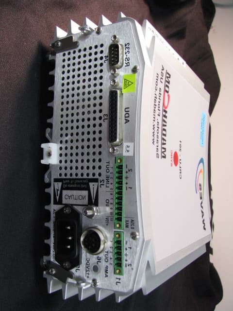
X2PCRLU-201
May 05, 2010EMERGENCY NOTIFICATION SYSTEM
Equipment Class
DSS - Part 15 Spread Spectrum Transmitter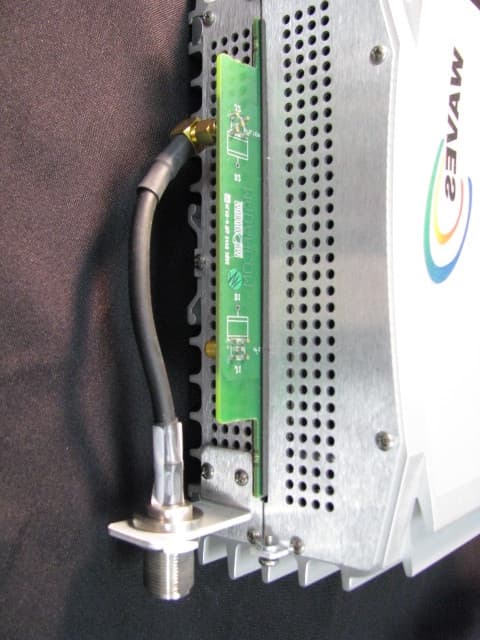
X2PTRX-401
Apr 27, 2010EMERGENCY NOTIFICATION SYSTEM
Equipment Class
DSS - Part 15 Spread Spectrum Transmitter