X4Y340U1IP Camera
NEXXT SOLUTIONS
Click to zoom
Application Details
- Equipment Class
- DTS - Digital Transmission System
- Date of Grant
- Feb 03, 2013
- Application Purpose
- Original Equipment
- Date of Application
- Feb 03, 2013
- Equipment Note
- IP Camera
- Frequency Range
- 2412.00000000 - 2462.00000000
- Company
- NEXXT SOLUTIONS
- Country
- United States
Documents & Files
Document Text
Text extracted from the exhibit documents filed with the FCC. Open a document above to read the original.
Users Manual
Nexxt Solutions - Integrated Wireless IP Camera 2 Integrated Wireless IP Camera INTRODUCTION Thank you for purchasing the Nexxt Solutions XPY 300 Camera. Our new XPY is an integrated wireless IP Camera solution that combines a high quality digital video camera with network connectivity and a powerful web server to bring a clear picture to your desktop or mobile phone from anywhere on your local network or over the Internet. Nexxt Solutions - Integrated Wireless IP Camera 3 This camera is intended for indoor use only. Use the supplied power adaptor to connect the camera to the AC mains (5.0V DC, 1.5A). The warranty does not cover any damage caused by applying the wrong voltage. Never attempt to disassemble the unit. The warranty does not cover damages as a result of tampering with, or the improper alteration of the device. Do not point the camera at the sun or at any other strong light source. Do not install the camera where it can be exposed to rain or water Wait at least 10 seconds when powering the camera on and off. Otherwise, it can cause serious damage to the CPU. When updating the camera, please make sure that: the camera is connected directly to a computer using a network cable; all other programs and windows on the computer have been closed; the camera remains connected during the entire firmware update. • • • • • • • - - - BEFORE YOU BEGIN Nexxt Solutions - Integrated Wireless IP Camera 4 NOTES ON WINDOWS AND MAC COMPATIBILITY: FEATURES The camera combines a high-sensitivity 1/4 CMOS image sensor with a powerful wireless web server in order to capture clear images from anywhere, and to transmit them instantly on your local network or over the internet. Can be used on WiFi or wired networks. Selectable image resolution of 640x480 and 320x240 pixels. The system can be expanded at any time by adding multiple cameras. View multiple cameras in split screen view or choose full screen in order to monitor the activity from a single camera. Cameras can be viewed via standard PC or Mac browsers, including Internet Explorer, Safari, Chrome and Firefox. Infrared LEDs for night vision (up to 15 meters). Includes multi-level user management system, which can be configured with passwords for controlled access. Easy- to-use web browser controls. They also allow quick configuration changes via the settings menu. Compatibility with smartphones enables you to view real-time videos over the internet using any standard browser. Supports image snapshots and image forwarding via email and FTP upload. IP camera setup should be completed on a Windows PC only using Internet Explorer. Live viewing, taking snapshots, recording and camera configuration are fully supported on computers with Windows operating systems. • • • • • • • • • • • - - Nexxt Solutions - Integrated Wireless IP Camera 5 NOTE: if any of the listed items are missing or damaged, please notify immediately the Nexxt Solutions reseller from whom you purchased the product for replacement or warranty information. Our WiFi Camera can be set up in minutes for instant monitoring and live viewing on your Windows computer and 3G Smartphone - all via your wireless network router or switch. For optional recording capabilities, simply install the recording software in your Windows PC and configure it according to your particular needs. view live images via compatible web browsers including Safari, Firefox and Chrome but are limited to viewing one camera at a time. take and save snapshot images via the web browser interface. Wireless IP Camera x1 AC power adaptor x1 Quick installation guide x1 CD-ROM x1 (includes the IP Super Client Software) Network cable x1 Mounting bracket and hardware • • • • • • - - PACKAGE CONTENTS CAMERA INSTALLATION Mac users are only able to: Open the box and make sure all items listed below are included: Nexxt Solutions - Integrated Wireless IP Camera 6 Begin by screwing the bracket to the camera. Connect the camera using the power adaptor that comes with the product. Using a standard Ethernet network cable, connect the camera to your network. The camera can either be connected to a router/ switch or directly to a PC with an Ethernet network cable. We recommend setting up the camera on your network using a wired connection prior to using the device in a wireless configuration. Continue with the setup of the camera (as described in the following chapter). Once the camera has been successfully connected to your network, it can be mounted on the wall or ceiling using the wall plugs and screws included with the device. (The initial set up must be performed using Windows operating system only). 1. Plug the cable into the RJ-45 connector on the rear of the camera.. 1. 2. 3. INTERNET Cellular Phone IP Camera Modem PDAComputer Intranet Internet connection Nexxt Solutions - Integrated Wireless IP Camera 7 2. Plug the other end into an available RJ-45 port on your router. 3. Connect the power cable to the wall outlet. Please note that if you are using the camera on a wireless network, you will need to configure the camera for wired use, prior to configuring wireless settings in the device (later described in this manual). Accessing the IP camera Using the IP Super Client Software Note: The IP network camera is designed to work in a local area network (LAN) or over the internet. For the first method, we highly recommend using the software included in the CD. The installation steps are described below. 1. Introduction The IP camera Super Client is an easy-to-use software designed for surveillance applications with multiple cameras. This software includes PT controls, recording, alarm notifications, in addition to a central management feature that allows the administration, configuration and access control settings for each individual device. Nexxt Solutions - Integrated Wireless IP Camera 8 Functions: *Supports up to 81-video monitoring in one screen *Supports multi-level structured device list. *Supports scheduled recording with alarm. *…
Text truncated - open the document above for the full version.
Users Manual
FCC INFORMATION This device complies with Part 15 of the FCC Rules. Operation is subject to the following two conditions: 1. This device may not cause harmful interference, and 2. This device must accept any interference received, including interference that may cause undesired operation. Note: This equipment has been tested and found to comply with the limits for a Class B digital device, pursuant to part 15 of the FCC Rules. These limits are designed to provide reasonable protection against harmful interference in a residential installation. This equipment generates, uses and can radiate radio frequency energy and, if not installed and used in accordance with the instructions, may cause harmful interference to radio communications. However, there is no guarantee that interference will not occur in a particular installation. If this equipment does cause harmful interference to radio or television reception, which can be determined by turning the equipment off and on, the user is encouraged to try to correct the interference by one or more of the following measures: —Reorient or relocate the receiving antenna. —Increase the separation between the equipment and receiver. —Connect the equipment into an outlet on a circuit different from that to which the receiver is connected. —Consult the dealer or an experienced radio/TV technician for help. Caution: Any changes or modifications not expressly approved by the party responsible for compliance could void the user's authority to operate this equipment. RF Exposure: A distance of 20 cm shall be maintained between the antenna and users, and the transmitter module may not be co-located with any other transmitter or antenna.
Cover Letter(s)
Nexxt Solutions FCC Confidentiality Request Number: CF303 Version: V05 Date: 21-05-2012 (Permanent or also called long term confidentiality is the normal method to keep certain docuements confidential, and may apply to schematics, block diagrams, operational description and bill of materials.) To: Federal Communications Commission Equipment Authorization Branch 7435 Oakland Mills Road Columbia, MD 21046 Pursuant to 47 CFR Section 0.459(a) & (b), we, (the applicant / grantee) Company nameNexxt Solutions Address3505 NW 107th Ave, Miami, Fl., 33178, USA CityMiami,Fl., 33178 CountryUSA request for this certification filing under: Grantee CodeProduct Number FCC ID:X4Y340U1 to maintain permanent confidentiality for the following documents submitted within this application: (please cross what is applicable, or add other documents) ExhibitDescription VOperational Descriptionexplaining the functioning of the block diagram VBlock Diagramsshowing the systematic building blocks of the EUT VSchematics Diagramsshowing components, their values and interconnection Above materials crossed contain secrets, proprietary and technical information, which would customarily be guarded from competitors under 47 CFR, section 0.457(d)(2). Disclosure or publication or any portion of this company confidential material to other parties could cause substantial competitive harm and provide unjustified benefits for competitors. We understand that pursuant to 47 CFR section 0.457(d)(1)(ii) disclosure of the applicant and all accompanying documentation will not be made before the date of the grant. The documents indicated as confidential above, are not publicly available elsewhere. Attestation: City and Country:Date:Name: (this must be a person) Function:Signature: (or official company stamp) Enschede, The Netherlands 25-01-2012M.Koop (authorized) Manager
Cover Letter(s)
Nexxt Solutions FCC Authorization Letter Number: CF304 Version: V03 Date: 01-08-2011 We, (the approval holder) Company name Nexxt Solutions Address 3505 NW 107th Ave, Miami, Fl., 33178, USA City Miami Country USA declare that the following representative (agent): Name (person) Tony Wu Company name Bontek Compliance Laboratory Co., Ltd. Address 1/F, Block East H-3,OCT Eastern Ind. Zone, Qiaocheng East Road, Nanshan, City Shenzhen,Guangdong Country China is hereby authorized to apply the following equipment for certification on our behalf: Product Description IP Camera Type or Model(s) XPY300 Tradename or Brand(s) NEXXT We also authorize Teleconformity (Mr. M. Koop, Manager Certification, Address: Rietven 31, 7534NH Enschede, the Netherlands) to apply and sign this application for certification, registration or filing on our behalf (as representative agent or certifier). Attestation: City and Country: Date: Name: (this must be a person) Function: Signature: (or official company stamp) Miami, USA 2013-1-21 Naftali Mizrachi Vice President Miami, USA 2013-1-21
External Photos
EUT EXTERNAL PHOTOGRAPHS EUT –View EUT –Front View EUT –Rear View EUT –Side View EUT –Adapter View
ID Label/Location Info
FCC ID Label Location FCC ID Label Location
ID Label/Location Info
FCC ID Label Sample for FCC ID: X4Y340u1 Nexxt Solutions Product: IP Camera FCC ID: X4Y340U 1 Model: XPY300 for FCC ID: X4Y340U 1
Internal Photos
EUT INTERNAL PHOTOGRAPHS EUT –Uncovered View Antenna EUT PCB View EUT-LED PCB View EUT WIFI Module View EUT –WI-FI MODUL View ANTENNA
RF Exposure Info
MPE Calculation FCC ID: X4Y340U1 Typical use distance: d ≥ 20 cm Power density limit for mobile devices at 2.4 GHz: S ≤ 1 mW/cm 2 Remark: Average ≤ Peak, which means that calculating the power density applying Peak power is worst case. The worst case operation mode generating the highest power in each frequency range is taken for calculation. Frequency range: 2412-2462MHz Maximum measured conducted power (Peak): P conducted = 16.36 dBm Antenna Gain: G = 2 dBi Calculation: P radiated = P conducted + G linear = 16.36 dBm + 2 dBi = 18.36 dBm = 68.55 mW Power density S = (P radiated ) / (4π x d 2 ) = 68.55 / 5026 = 0.0137 mW/cm 2 which is below limit, pass. Frequency range: 2422-2452MHz Maximum measured conducted power (Peak): P conducted = 10.66 dBm Antenna Gain: G = 2 dBi Calculation: P radiated = P conducted + G linear = 10.66 dBm + 2 dBi = 12.66 dBm = 18.45 mW Power density S = (P radiated ) / (4π x d 2 ) = 18.45 / 5026 = 0.00367 mW/cm 2 which is below limit, pass.
Test Report
Test Report of FCC CFR 47 Part 15 Subpart C On Behalf of Nexxt Solutions FCC ID: X4Y340U1 Product Description: IP Camera Model No.: XPY300 Supplementary Model: N/A Brand Name: NEXXT Prepared for: Nexxt Solutions 3505 NW 107th Ave, Miami, Fl., 33178, USA Prepared by: Bontek Compliance Testing Laboratory Co., Ltd 1/F, Block East H-3, OCT Eastern Ind. Zone, Qiaocheng East Road, Nanshan, Shenzhen, China Tel: 86-755-86337020 Fax: 86-755-86337028 Report No.: BCT12KR-2203E Issue Date: January 19, 2013 Test Date: November 26, 2012~January 19, 2013 Tested by: Reviewed by: Lion Cai Kendy Wang Approved by: Tony Wu Report No.: BCT12KR-2203E Page 2 of 71 FCC ID: X4Y340U1 TABLE OF CONTENTS 1. GENERAL INFORMATION........................................................................................................................ 3 1.1 PRODUCT DESCRIPTION FOR EQUIPMENT UNDER TEST (EUT) .................................................................. 3 1.2 TEST STANDARDS................................................................................................................................... 3 1.3 TEST FACILITY........................................................................................................................................ 4 2. SYSTEM TEST CONFIGURATION ........................................................................................................... 5 2.1 EUT CONFIGURATION............................................................................................................................. 5 2.2 EUT EXERCISE....................................................................................................................................... 5 2.3 GENERAL TEST PROCEDURES................................................................................................................. 5 2.4 MEASUREMENT UNCERTAINTY................................................................................................................. 5 2.5 LIST OF MEASURING EQUIPMENTS USED.................................................................................................. 6 3. SUMMARY OF TEST RESULTS ............................................................................................................... 7 4. TEST OF AC POWER LINE CONDUCTED EMISSION ........................................................................... 8 4.1 APPLICABLE STANDARD........................................................................................................................... 8 4.2 TEST SETUP DIAGRAM............................................................................................................................ 8 4.3 TEST RESULT......................................................................................................................................... 8 5. TEST OF MAXIMUM PEAK OUTPUT POWER ...................................................................................... 11 5.1 APPLICABLE STANDARD......................................................................................................................... 11 5.2 EUT SETUP.......................................................................................................................................... 11 5.3 TEST EQUIPMENT LIST AND DETAILS...................................................................................................... 11 5.4 TEST PROCEDURE................................................................................................................................11 5.5 TEST RESULT....................................................................................................................................... 11 6. TEST OF PEAK POWER SPECTRAL DENSITY ................................................................................... 21 6.1 APPLICABLE STANDARD......................................................................................................................... 21 6.2 EUT SETUP.......................................................................................................................................... 21 6.3 TEST EQUIPMENT LIST AND DETAILS...................................................................................................... 21 6.4 TEST PROCEDURE................................................................................................................................21 6.5 TEST RESULT....................................................................................................................................... 21 7. TEST OF 6DB BANDWIDTH ................................................................................................................... 31 7.1 APPLICABLE STANDARD......................................................................................................................... 31 7.2 EUT SETUP.......................................................................................................................................... 31 7.3 TEST EQUIPMENT LIST AND DETAILS...................................................................................................... 31 7.4 TEST PROCEDURE................................................................................................................................31 7.5 TEST RESULT....................................................................................................................................... 31 8. TEST OF CONDUCTED SPURIOUS EMISSION.................................................................................... 42 8.1 APPLICABLE STANDARD......................................................................................................................... 42 8.2 EUT SETUP.......................................................................................................................................... 42 8.3 TEST EQUIPMENT LIST AND DETAILS......................................................…
Text truncated - open the document above for the full version.
Test Setup Photos
TEST SETUP PHOTOGRAPHS Conducted Emission Conducted Emission Radiated Emission Radiated Emission Radiated Emission Above 1GHz
Contact Information
Applicant
Albert Mizrachi(Vice president of product development)
Technical Contact
Test Firm
Bontek Compliance Testing Laboratory LtdTony Wu
Technical Specifications
| # | Rule Parts | Frequency Range | Power Output |
|---|---|---|---|
| 1 | 15C | 2.41 GHz - 2.46 GHz | 43.00 mW |
Other Applications from NEXXT SOLUTIONS
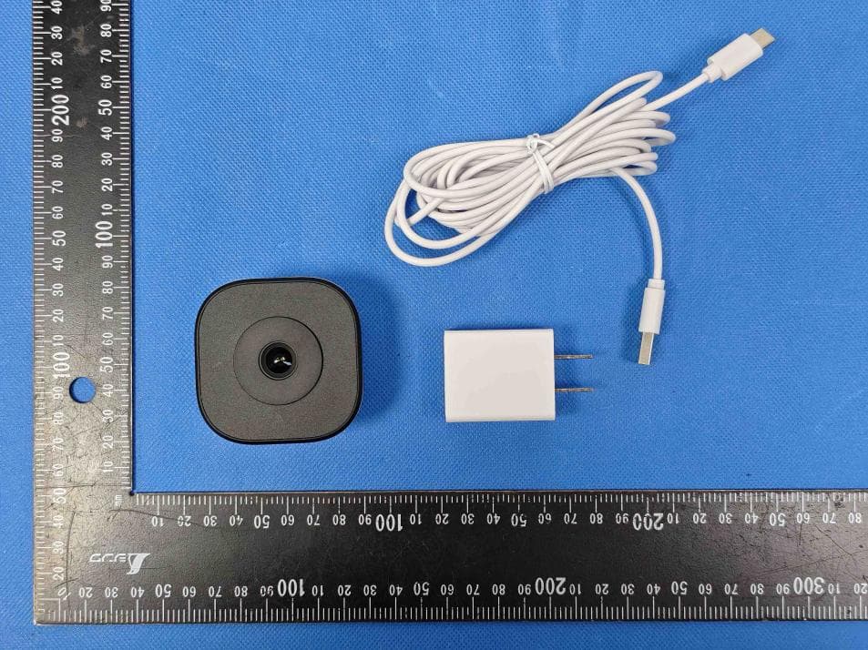
X4YHACIF25W
Aug 06, 2026Smart Camera
Equipment Class
DTS - Digital Transmission System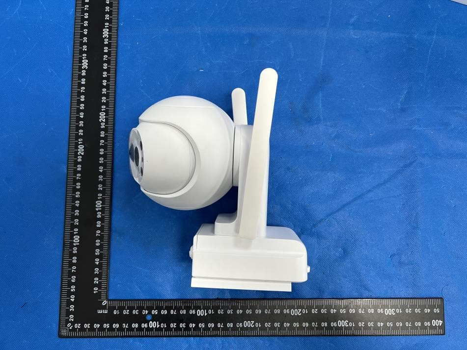
X4YHACOP40SL
Jul 07, 2026Smart Camera
Equipment Class
PCB - PCS Licensed Transmitter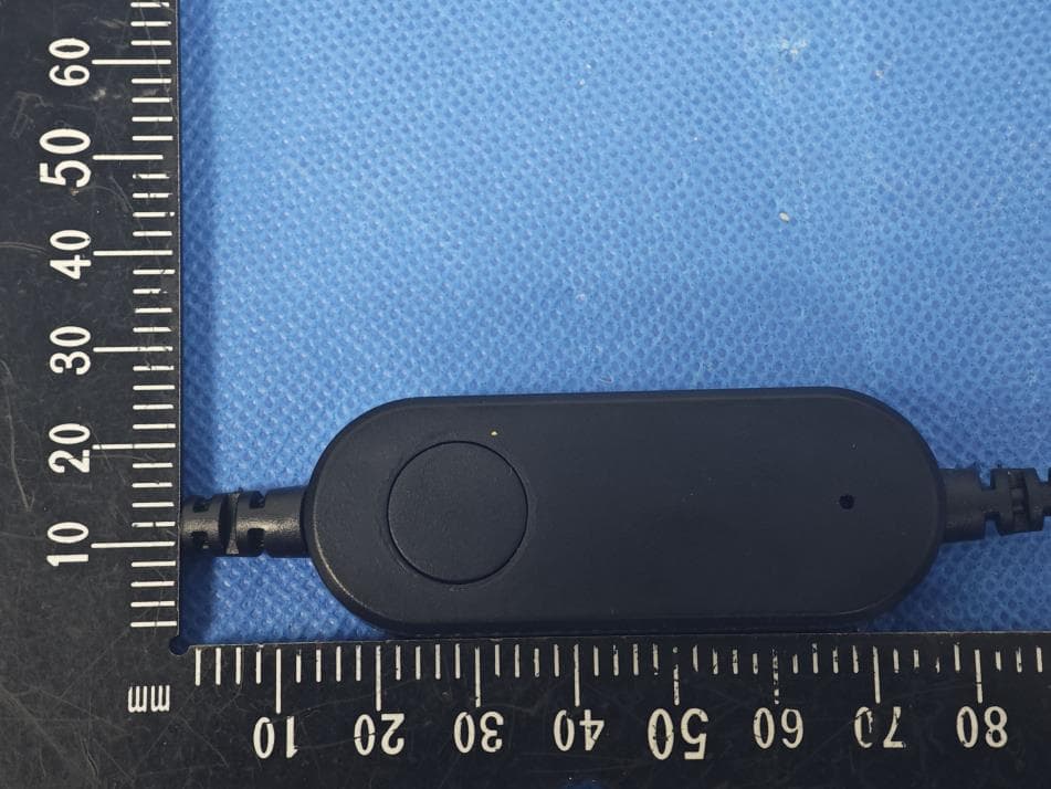
X4YHABXL20
Jan 14, 2026Xmas string lights
Equipment Class
DTS - Digital Transmission System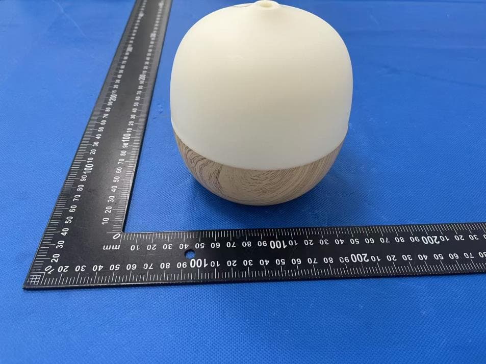
X4YHAAD300
Jan 06, 2026AROMA DIFFUSER
Equipment Class
DTS - Digital Transmission System
X4YHACIP15
Sep 28, 2025Camera
Equipment Class
DTS - Digital Transmission System