X4Y350U12.4GHz High Power Wireless Outdoor Access Point
NEXXT SOLUTIONS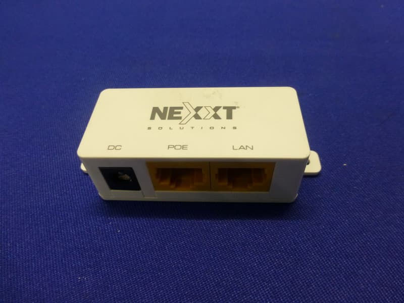
Click to zoom
Application Details
- Equipment Class
- DTS - Digital Transmission System
- Date of Grant
- Apr 24, 2013
- Application Purpose
- Original Equipment
- Date of Application
- Apr 22, 2013
- Equipment Note
- 2.4GHz High Power Wireless Outdoor Access Point
- Frequency Range
- 2412.00000000 - 2462.00000000
- Company
- NEXXT SOLUTIONS
- Country
- United States
Documents & Files
Document Text
Text extracted from the exhibit documents filed with the FCC. Open a document above to read the original.
Users Manual
Nexxt Solutions - NetGate Wireless Access Point 2 Copyright Statement Nexxt Solutions™ is a registered trademark. Other trademarks or brand names contained herein are the trademarks or registered brand names of their respective owners. Copyright of the whole product as integration, including its accessories and software, belongs to Nexxt Solutions Ltd. No individual or third party is allowed to copy, plagiarize, reproduce, or translate it into other languages, without express consent from Nexxt Solutions, Ltd. All of the photos and product specifications mentioned in this manual are used as reference only. Upgrades of software and hardware may occur, and should there be any changes, Nexxt Solutions shall not be responsible for notifying about any such modifications in advance. If you would like to know more about our products, please visit our website at www.NexxtSolutions.com. Nexxt Solutions - NetGate Wireless Access Point 3 This equipment has been tested and found to comply with the limits for a Class B digital device, pursuant to part 15 of the FCC Rules. These limits are designed to provide reasonable protec- tion against harmful interference in a residential installation. This equipment generates, uses and can radiate radio frequency energy and, if not installed and used in accordance with the instructions, may cause harmful interference to radio communications. However, there is no guarantee that interference will not occur in a particular installation. If this equipment does cause harmful interference to radio or television reception, which can be determined by turning the equipment off and on, the user is encouraged to try to correct the interference by one or more of the following measures: Any changes or modications not expressly approved by the party responsible for compliance could void the user’s authority to operate the equipment. Note: The manufacturer is not responsible for any radio or TV interference caused by unauthorized modications to this equipment. Such modications could void the user’s authority to operate the equipment. This equipment complies with FCC RF radiation exposure limits set forth for an uncontrolled environment. This device and its antenna must not be co-located or operating in conjunction with any other antenna or transmitter. “T o comply with FCC RF exposure compliance requirements, this grant is applicable to only Mobile Congurations. The antennas used for this transmitter must be installed to provide a separation distance of at least 30 cm from all persons and must not be co-located or operating in conjunction with any other antenna or transmitter.” This device complies with part 15 of the FCC Rules. Operation is subject to the following two conditions: Reorient or relocate the receiving antenna. Increase the separation between the equipment and receiver. Connect the equipment into an outlet on a circuit different from that to which the receiver is connected. Consult the dealer or an experienced radio/TV technician for help. This device may not cause harmful interference. This device must accept any interference received, including interference that may cause undesired operation. 1. 2. FCC STATEMENT FCC RF Radiation Exposure Statement • • • • Nexxt Solutions - NetGate Wireless Access Point 4 CONTENTS Product overview Features LED definition Rear panel layout and connectos System requirements Environment requirements Connecting the device Checking the LEDs Initial configuration Quick setup wizard Login Status Quick setup Operation mode Network LAN WAN MAC clone Wireless Basic settings Wireless mode Security settings MAC filtering Wireless statistics Distance setting Antenna alignment Throughput monitor DHCP DHCP settings DHCP clients list Address reservation Wireless settings Forwarding Virtual servers Port triggering DMZ UPnP Security Firewall IP address filtering Domain filtering 1.1 1.2 2.1 2.2 2.3 2.4 2.5 3.1 3.2 3.3 4.1 4.2 4.3 4.4 4.5 4.5.1 4.5.2 4.5.3 4.6 4.6.1 4.6.2 4.6.3 4.6.4 4.6.5 4.6.6 4.6.7 4.6.8 4.7 4.7.1 4.7.2 4.7.3 4.8 4.9 4.9.1 4.9.2 4.9.3 4.9.4 4.10 4.10.1 4.10.2 4.10.3 Chapter 1 Introduction Chapter 2 Device layout Chapter 3 Quick installation guide Chapter 4 AP Client Router & AP Router Operation Mode Nexxt Solutions - NetGate Wireless Access Point 5 Package Contents Appendix A: FAQ Appendix B: Configuring the PC Appendix C: Specifications Appendix D: Glossary 4.10.4 4.10.5 4.10.6 4.11 4.12 4.12.1 4.12.2 4.13 4.13.1 4.13.2 4.13.3 4.14 4.14.1 4.14.2 4.15 4.15.1 4.15.2 4.15.3 4.15.4 4.15.5 4.15.6 4.15.7 4.15.8 4.15.9 4.15.10 MAC address filtering Remote management Advanced security Static routing IP & MAC binding Binding setting ARP list Dynamic DNS Dyndns.org DDNS Oray.net DDNS Comexe.cn DDNS SNMP Community setting SNMP system setting System tools Time Firmware Factory defaults Backup & restore Ping Watch Dog Speed test Reboot Password Syslog Statistics Upon opening the box, make sure that the following items are included: High Power Wireless Access Point Power adapter PSE module Mounting kit Quick installation guide Resource CD Note: If any of the listed items is missing, mismatched, damaged or broken, contact your local dealer immediately for replacement. • • • • • • Nexxt Solutions - NetGate Wireless Access Point 6 1.2 Features 1.1 Product overview Chapter 1 Introduction Thank you for purchasing the AELPLDR4U1 High Power Wireless Outdoor Access Point from Nexxt Solutions. The 2.4 GHz High Power Wireless Outdoor Access Point is a dedicated Wireless Internet Service Provider Customer-Premises Equipment (WISP CPE) device, providing the functions of a Wireless Access Point (WAP), WISP Client, and a high-gain antenna in one weatherproof de- vice designed for outdoor use. The high power design extends transmission range and delivers a more reliable wireless connection. Equipped with a Power over Ethernet Port known as PoE, this device can be installed in locations where AC power is not readily available. It also features a web-based…
Text truncated - open the document above for the full version.
Users Manual
Nexxt Solutions - NetGate Wireless Access Point 41 • • • • Protocol - The protocol used for this application, either TCP, UDP, or All (all protocols supported by the router). Status - This field displays either Enabled or Disabled, as the current status for the device. Modify - Click the Modify button next to in the entry you want to change. If you want to erase that entry, click on Delete. Common Service Port - Some common services are already available from the pull-down list. To setup a virtual server entry, follow the steps described below: Click the Add New... button on the virtual servers page. (Figure 4-29) Select the service you want to use from the Common Service Port list. If the Common Service Port list does not have the service that you want to use, type the number of the service port or service port range in the Service Port field. Type the IP Address of the computer in the Server IP Address field. Select the protocol used for this application. Select the Enable option to activate the virtual server. Click the Save button. Click the Modify button next to the entry you want to modify. If you want to erase this entry, click on the Delete button. Proceed with the changes you want to make. Click the Save button when you are done. Click the Enable All button to activate all entries. Click the Disabled All button to cancel all entries. Click the Delete All button to erase all entries. Click the Next button to go to the following page. Click the Previous button to return to the last page. Note: If you set the virtual server of service port as 80, you must configure the Web management port on System Tools –> Remote Management page to be any value other than 80, such as 8080. Otherwise, there will be a conflict to disable the virtual server. 1. 2. 3. 4. 5. 6. 1. 2. 3. Note: If your computer or server has more than one type of service available, please select a different service, and enter the same IP Address for that computer or server. To modify or delete an existing entry: Figure 4-29 Add or Modify a Virtual Server Entry Nexxt Solutions - NetGate Wireless Access Point 42 4.9.2 Port triggering Go to Forwarding > Port Triggering in order to configure the Port Triggering parameters on this menu, as shown in Figure 4-30. Once configured, the operation is as follows: To add a new rule, follow the steps below: A local host makes an outgoing connection to an external host using a destination port number defined in the Trigger Port field. The router records this connection, opens the incoming port or ports associated with this entry in the Port Triggering table, and associates them with the local host. When necessary, the external host will be able to connect to the local host using one of the ports defined in the Incoming Ports field. Click the Add New... button o the Port Triggering page. (Figure 4-31) Select a common application from the Common Applications drop-down list, then the port parameters will be automatically filled in the corresponding field. If the Common Applications list does not have the application you want, enter the port parameters manually. Select the protocol used for Trigger Port and Incoming Ports from the corresponding pull-down list. Click on Enable on the Status field. Click the Save button to save the new rule. 1. 2. 3. 1. 2. 3. 4. 5. • • • • • Trigger Port - The port for outgoing traffic. An outgoing connection using this port will “Trigger” this rule. Trigger Protocol - The protocol used for Trigger Ports, either TCP, UDP, or All (all protocols supported by the router). Incoming Ports Range - The port or port range used by the remote system when it responds to the outgoing request. A response using one of these ports will be forwarded to the PC that triggered this rule. You can input at most 5 groups of ports (or port section). Every group of ports must be separated by commas “,”. For example, 2000-2038, 2050-2051, 2085, 3010-3030. Incoming Protocol - The protocol used for Incoming Ports Range, either TCP , UDP, or ALL (all protocols supported by the router). Status - This field displays either Enabled or Disabled, as the current status for the device. Figure 4-30 Port triggering Nexxt Solutions - NetGate Wireless Access Point 43 To modify or delete an existing entry, please complete the steps below: Note: Click the Enable All button to activate all entries. Click the Disabled All button to cancel all entries. Click the Delete All button to erase all entries. Click the Modify button next to the entry you want to change. If you want to delete that entry, click the Delete in this stage. Proceed with the changes you want to make. Click the Save button when you are done. When the trigger connection is released, will cause the closing of the corresponding opened ports. Each rule can only be used by one host on the LAN at a time. The trigger connection of other hosts on the LAN will be refused. Incoming Port Range enabled cannot overlap each other at the same time. 1. 2. 3. 1. 2. 3. 4.9.3 DMZ (Demilitarized Zone) Go to Forwarding > DMZ in order to set up an DMZ host on this page, as shown in Figure 4-32. Figure 4-31 Add or Modify a Triggering Entry Figure 4-32 DMZ Nexxt Solutions - NetGate Wireless Access Point 44 To assign a computer or server to be a DMZ server: Note: Once you set the DMZ host, the firewall protection for that host will be disabled. Click the Enable radio button. Enter the IP address in the DMZ Host IP Address field of the local PC that you want to set as the DMZ host. Click the Save button when done. 1. 2. 3. • • • • • • • • Current UPnP Status - UPnP can be enabled or disabled by clicking the corresponding button. As enabling UPnP may present a risk to security, this feature is disabled by default. Current UPnP Settings List - This table displays the current UPnP information. Click Enable to activate the UPnP feature. Click Disable to cancel the UPnP feature. Click Refresh to update the Current UPnP Settings List. App Description - The descript…
Text truncated - open the document above for the full version.
Cover Letter(s)
Attestation for FCC Declaration of Conformity FCC ID:X4Y350U1 Date: Mar. 4, 2013 Please be notified that we, the undersigned, NEXXT SOLUTIONS LLC declare that the product bears the above FCC ID is also complying with the requirements of FCC DoC. The test report number for FCC DoC is EM-F1020170 , with is issued by an accredited lab, Audix Technology Corporation, EMC Department located at No. 53-11, Tin-Fu Tsun, Lin-Kou , Taipei Hsien , Taiwan. Which has been accredited in accordance to all of the requirements of 47CFR 2.948(d) and (e) of the FCC rules and KDB349827.
Cover Letter(s)
AGENCY AUTHORIZATION LETTER FCC ID:X4Y350U1 Date: Mar. 4, 2013 To whom it may concern: We, the undersigned, hereby authorize Audix Technology (Shenzhen) Co., Ltd (No. 6, Ke Feng Rd., 52 Block, Shenzhen Science & Industrial Park,Nantou,Shenzhen, Guangdong, China) to act on our behalf, as our agent, in the following matters related to the FCC approval of our products: report submittal, related correspondence, the signing of all documents relating to these matters, and any other lawful activity necessary to obtain such certification. Any act carried out by Audix within the scope of this authorization shall have the same effects as our own. This authorization shall expire 6 months form original date. If you have any Questions regarding the authorization, please don’t hesitate to contact us. Thank you.
Cover Letter(s)
Date: Mar. 4, 2014 Federal Communications Commission Authorization and Evaluation Division FCC ID: X4Y350U1 Confidentiality Request Pursuant to Sections 0.457 and 0.459 of the Commission’s Rules, the Applicant hereby requests confidential treatment of information accompanying this application as outlined below: 1. Block diagram 2. Schematics 3. Operation Description The above materials contain trade secrets and proprietary information not customarily released to the public. The public disclosure of these matters might to harmful to the applicant and provide unjustified benefits to its competitors. The applicant understands that pursuant to Rule 0.457, disclosure of this application and all accompanying documentation will not be made before the date of the grant for this application.
External Photos
R AUDIX Technology (Shenzhen) Co., Ltd. FCC ID:X4Y350U1 page Audix Technology (Shenzhen) Co., Ltd. Report No. ACS-F13047 14-1 14. PHOTOS OF THE EUT Figure 1 General Appearance of the EUT Figure 2 General Appearance of the EUT R AUDIX Technology (Shenzhen) Co., Ltd. FCC ID:X4Y350U1 page Audix Technology (Shenzhen) Co., Ltd. Report No. ACS-F13047 14-2 Figure 3 General Appearance of the EUT Figure 4 General Appearance of the EUT R AUDIX Technology (Shenzhen) Co., Ltd. FCC ID:X4Y350U1 page Audix Technology (Shenzhen) Co., Ltd. Report No. ACS-F13047 14-3 Figure 5 General Appearance of the EUT Figure 6 Inside of the EUT
ID Label/Location Info
C B A 12 C 345678 B E D D A 9 料号: 12345 E 6789 与上一版的区别 颜 色 名 称 版 本 材 质 模 具 机型版本号 logo 底色 文字 其它 结构工程师 硬件工程师 产品工程师 平面负责人 记 录 审 核 完成日期 设 计 Label Location
Internal Photos
R AUDIX Technology (Shenzhen) Co., Ltd. FCC ID:X4Y350U1 page Audix Technology (Shenzhen) Co., Ltd. Report No. ACS-F13047 14-3 Figure 5 General Appearance of the EUT Figure 6 Inside of the EUT R AUDIX Technology (Shenzhen) Co., Ltd. FCC ID:X4Y350U1 page Audix Technology (Shenzhen) Co., Ltd. Report No. ACS-F13047 14-4 Figure 7 Inside of the EUT Figure 8 Inside of the EUT R AUDIX Technology (Shenzhen) Co., Ltd. FCC ID:X4Y350U1 page Audix Technology (Shenzhen) Co., Ltd. Report No. ACS-F13047 14-5 Figure 9 Components Side of the PCB Figure 10 Components Side of the PCB R AUDIX Technology (Shenzhen) Co., Ltd. FCC ID:X4Y350U1 page Audix Technology (Shenzhen) Co., Ltd. Report No. ACS-F13047 14-6 Figure 11 Components Side of the PCB Figure 12 Components Side of the PCB R AUDIX Technology (Shenzhen) Co., Ltd. FCC ID:X4Y350U1 page Audix Technology (Shenzhen) Co., Ltd. Report No. ACS-F13047 14-7 Figure 13 Power Adapter Figure 14 Power Adapter Figure 15 R AUDIX Technology (Shenzhen) Co., Ltd. FCC ID:X4Y350U1 page Audix Technology (Shenzhen) Co., Ltd. Report No. ACS-F13047 14-8 Power Adapter
RF Exposure Info
R AUDIX Technology (Shenzhen) Co., Ltd. FCC ID:X4Y350U1 page Audix Technology (Shenzhen) Co., Ltd. Report No. ACS-F13047 11-1 11. MPE ESTIMATION 11.1.Limit for General Population/ Uncontrolled Exposures Frequency Power density (mW/ cm 2 ) Averaging time(minutes) 300MHz----1.5GHz F/1500 30 1.5GHz---100GHz 1.0 30 Frequency(MHz) Power density (mW/ cm 2 ) Averaging time(minutes) 2412 1 30 2437 1 30 2462 1 30 Note: F= Frequency in MHz 11.2.Estimation Method Have the power(P),and the antenna Gain(G),then calculate the MPE with below formula: MPE=(P*G)/4∏R2 Note:R=Estimation distance (R=30cm) R AUDIX Technology (Shenzhen) Co., Ltd. FCC ID:X4Y350U1 page Audix Technology (Shenzhen) Co., Ltd. Report No. ACS-F13047 11-2 11.3. Estimation Result EUT: 2.4GHz High Power Wireless Outdoor Access Point M/N: AELPLDR4U1 Test date: 2013-02-20 Pressure: 100.6±1 kpa Humidity: 60±3% Testd by: Leo Li Test site: RF Site Temperature:26±0.6 °C Antenna Type Mode CH Frequency (MHz) PK Output power (dBm) Output power (mW) antenna Gain (dBi) antenna Gain (linear) MPE Vertical 11b 1 2412 25.30 338.84 12 15.85 0.4751 6 2437 25.40 346.74 12 15.85 0.4861 11 2462 23.80 239.88 12 15.85 0.3363 11g 1 2412 25.37 344.35 12 15.85 0.4828 6 2437 26.25 421.70 12 15.85 0.5912 11 2462 24.02 252.35 12 15.85 0.3538 Horizontal 11b 1 2412 25.45 350.75 12 15.85 0.4918 6 2437 24.72 296.48 12 15.85 0.4157 11 2462 24.38 274.16 12 15.85 0.3844 11g 1 2412 25.72 373.25 12 15.85 0.5233 6 2437 25.90 389.05 12 15.85 0.5455 11 2462 24.32 270.40 12 15.85 0.3791 External 11b 1 2412 24.27 267.30 9 7.94 0.1878 6 2437 24.79 301.30 9 7.94 0.2117 11 2462 23.58 228.03 9 7.94 0.1602 11g 1 2412 25.81 381.07 9 7.94 0.2678 6 2437 26.04 401.79 9 7.94 0.2823 11 2462 24.27 267.30 9 7.94 0.1878
Test Report
R AUDIX Technology (Shenzhen) Co., Ltd. FCC ID:X4Y350U1 page Audix Technology (Shenzhen) Co., Ltd. Report No. ACS-F13047 1-1 FCC PART 15C TEST REPORT FOR CERTIFICATION On Behalf of NEXXT SOLUTIONS LLC 2.4GHz High Power Wireless Outdoor Access Point Model No.: AELPLDR4U1 FCC ID: X4Y350U1 Prepared for : NEXXT SOLUTIONS LLC 454 Holiday Drive, Hallandale, Florida, 33009 USA Prepared By : Audix Technology (Shenzhen) Co., Ltd. No. 6, Ke Feng Rd., 52 Block, Shenzhen Science & Industrial Park, Nantou, Shenzhen, Guangdong, China Tel: (0755) 26639496 Report Number : ACS-F13047 Date of Test : Feb.20~25, 2013 Date of Report : Mar.06, 2012 R AUDIX Technology (Shenzhen) Co., Ltd. FCC ID:X4Y350U1 page Audix Technology (Shenzhen) Co., Ltd. Report No. ACS-F13047 1-2 TABLE OF CONTENTS Description Page 1. SUMMARY OF STANDARDS AND RESULTS ......................................................... 1-1 1.1. Description of Standards and Results ................................................................................... 1-1 2. GENERAL INFORMATION ......................................................................................... 2-1 2.1. Description of Device (EUT) ............................................................................................... 2-1 2.2. Test Information ................................................................................................................... 2-2 2.3. Tested Supporting System Details ........................................................................................ 2-3 2.4. Block Diagram of Test Setup ............................................................................................... 2-3 2.5. Test Facility .......................................................................................................................... 2-4 2.6. Measurement Uncertainty (95% confidence levels, k=2) ..................................................... 2-4 3. POWER LINE CONDUCTED EMISSION TEST ....................................................... 3-1 3.1. Test Equipments ................................................................................................................... 3-1 3.2. Block Diagram of Test Setup ............................................................................................... 3-1 3.3. Power Line Conducted Emission Test Limits ...................................................................... 3-1 3.4. Configuration of EUT on Test .............................................................................................. 3-1 3.5. Operating Condition of EUT ................................................................................................ 3-2 3.6. Test Procedure ...................................................................................................................... 3-2 3.7. Power Line Conducted Emission Test Results ..................................................................... 3-2 4. RADIATED EMISSION TEST ...................................................................................... 4-1 4.1. Test Equipment ..................................................................................................................... 4-1 4.2. Block Diagram of Test Setup ............................................................................................... 4-1 4.3. Radiated Emission Limit ...................................................................................................... 4-2 4.4. EUT Configuration on Test .................................................................................................. 4-3 4.5. Operating Condition of EUT ................................................................................................ 4-3 4.6. Test Procedure ...................................................................................................................... 4-3 4.7. Radiated Emission Test Results ........................................................................................... 4-4 5. CONDUCTED SPURIOUS EMISSIONS ..................................................................... 5-1 5.1. Test Equipment ..................................................................................................................... 5-1 5.2. Limit ..................................................................................................................................... 5-1 5.3. Test Procedure ...................................................................................................................... 5-1 5.4. Test result ............................................................................................................................. 5-1 6. BAND EDGE COMPLIANCE TEST ............................................................................ 6-1 6.1. Test Equipment ..................................................................................................................... 6-1 6.2. Limit ..................................................................................................................................... 6-1 6.3. Test Produce ......................................................................................................................... 6-1 6.4. Test Results .......................................................................................................................... 6-1 7. 6dB Bandwidth Test ........................................................................................................ 7-1 7.1. Test Equipment ..................................................................................................................... 7-1 7.2. Limit ..................................................................................................................................... 7-1 7.3. Test Procedure ...................................................................................................................... 7-1 7.4. Test Results ....…
Text truncated - open the document above for the full version.
Test Setup Photos
R AUDIX Technology (Shenzhen) Co., Ltd. FCC ID:X4Y350U1 page Audix Technology (Shenzhen) Co., Ltd. Report No. ACS-F13047 13-1 13. PHOTOGRAPH OF TEST 13.1.Photos of Power Line Conducted Emission Test R AUDIX Technology (Shenzhen) Co., Ltd. FCC ID:X4Y350U1 page Audix Technology (Shenzhen) Co., Ltd. Report No. ACS-F13047 13-2 13.2.Photos of Radiated Emission Test R AUDIX Technology (Shenzhen) Co., Ltd. FCC ID:X4Y350U1 page Audix Technology (Shenzhen) Co., Ltd. Report No. ACS-F13047 13-3 (Above 1000MHz)
Contact Information
Applicant
Albert Mizrachi(Vice president of product development)
Technical Contact
AUDIX Technology (Shenzhen) Co., Ltd.Sun Zeng
[email protected]86-755-26639497
52 Block Shenzhen Science & Industry. · Shenzhen Guang Dong · China
Test Firm
Audix Technology (Shenzhen) Co., Ltd.Smart Tsai
Technical Specifications
| # | Rule Parts | Frequency Range | Power Output |
|---|---|---|---|
| 1 | 15C | 2.41 GHz - 2.46 GHz | 421.70 mW |
Other Applications from NEXXT SOLUTIONS
X4YHACIF25W
Aug 06, 2026Smart Camera
Equipment Class
DTS - Digital Transmission System
X4YHACOP40SL
Jul 07, 2026Smart Camera
Equipment Class
PCB - PCS Licensed Transmitter
X4YHABXL20
Jan 14, 2026Xmas string lights
Equipment Class
DTS - Digital Transmission System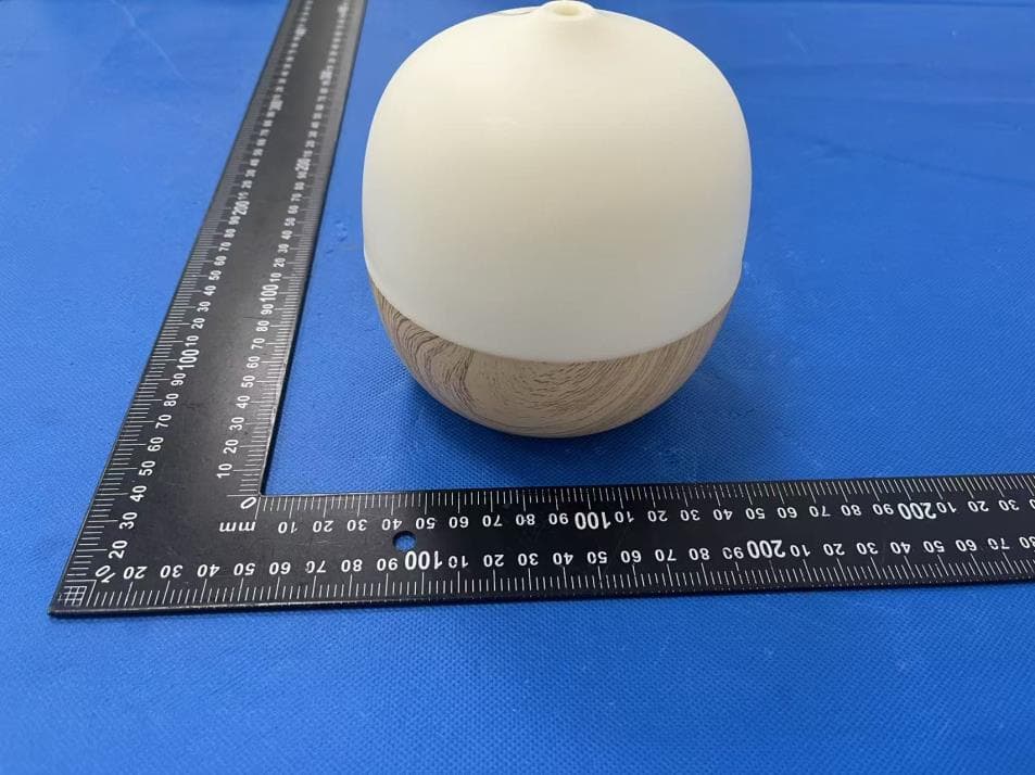
X4YHAAD300
Jan 06, 2026AROMA DIFFUSER
Equipment Class
DTS - Digital Transmission System
X4YHACIP15
Sep 28, 2025Camera
Equipment Class
DTS - Digital Transmission System